2011 NISSAN TIIDA AT-213
[x] Cancel search: AT-213Page 230 of 3787
SHIFT CONTROL SYSTEMAT-213
< SERVICE INFORMATION >
DE
F
G H
I
J
K L
M A
B
AT
N
O P
SHIFT CONTROL SYSTEM
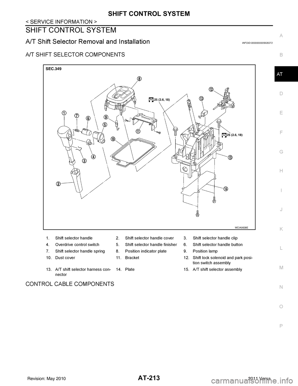
A/T Shift Selector Removal and InstallationINFOID:0000000005928272
A/T SHIFT SELECTOR COMPONENTS
CONTROL CABLE COMPONENTS
1. Shift selector handle 2. Shift selector handle cover 3. Shift selector handle clip
4. Overdrive control switch 5. Shift selector handle finisher 6. Shift selector handle button
7. Shift selector handle spring 8. Position indicator plate 9. Position lamp
10. Dust cover 11. Bracket12. Shift lock solenoid and park posi-
tion switch assembly
13. A/T shift selector harness con- nector 14. Plate
15. A/T shift selector assembly
WCIA0638E
Revision: May 2010 2011 Versa
Page 233 of 3787
AT-216
< SERVICE INFORMATION >
SHIFT CONTROL SYSTEM
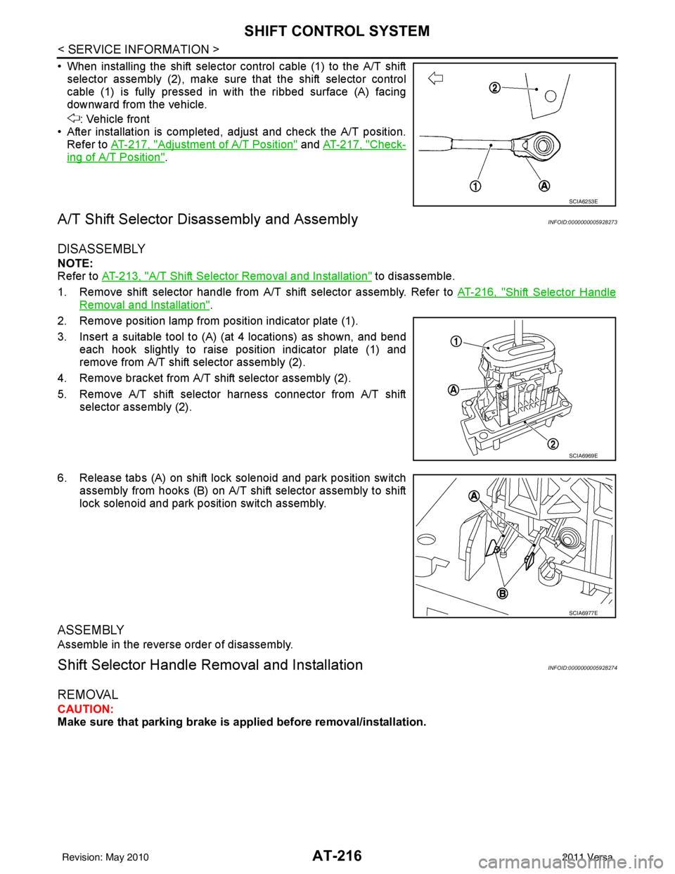
• When installing the shift selector control cable (1) to the A/T shiftselector assembly (2), make sure that the shift selector control
cable (1) is fully pressed in with the ribbed surface (A) facing
downward from the vehicle.
: Vehicle front
• After installation is completed, adjust and check the A/T position. Refer to AT-217, "
Adjustment of A/T Position" and AT-217, "Check-
ing of A/T Position".
A/T Shift Selector Di sassembly and AssemblyINFOID:0000000005928273
DISASSEMBLY
NOTE:
Refer to AT-213, "
A/T Shift Selector Removal and Installation" to disassemble.
1. Remove shift selector handle from A/T shift selector assembly. Refer to AT-216, "
Shift Selector Handle
Removal and Installation".
2. Remove position lamp from position indicator plate (1).
3. Insert a suitable tool to (A) (at 4 locations) as shown, and bend each hook slightly to raise position indicator plate (1) and
remove from A/T shift selector assembly (2).
4. Remove bracket from A/T shift selector assembly (2).
5. Remove A/T shift selector harness connector from A/T shift selector assembly (2).
6. Release tabs (A) on shift lock solenoid and park position switch assembly from hooks (B) on A/T shift selector assembly to shift
lock solenoid and park position switch assembly.
ASSEMBLY
Assemble in the reverse order of disassembly.
Shift Selector Handle Removal and InstallationINFOID:0000000005928274
REMOVAL
CAUTION:
Make sure that parking brake is applied before removal/installation.
SCIA6253E
SCIA6969E
SCIA6977E
Revision: May 2010 2011 Versa
Page 234 of 3787
SHIFT CONTROL SYSTEMAT-217
< SERVICE INFORMATION >
DE
F
G H
I
J
K L
M A
B
AT
N
O P
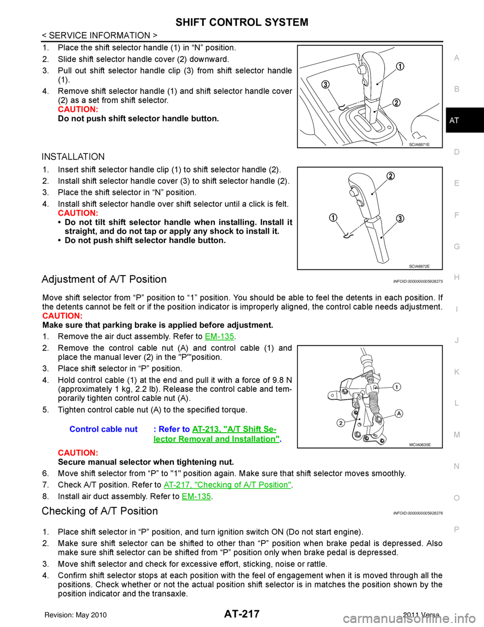
1. Place the shift selector handle (1) in “N” position.
2. Slide shift selector handle cover (2) downward.
3. Pull out shift selector handle clip (3) from shift selector handle (1).
4. Remove shift selector handle (1) and shift selector handle cover (2) as a set from shift selector.
CAUTION:
Do not push shift selector handle button.
INSTALLATION
1. Insert shift selector handle clip (1) to shift selector handle (2).
2. Install shift selector handle cover (3) to shift selector handle (2).
3. Place the shift selector in “N” position.
4. Install shift selector handle over shift selector until a click is felt.
CAUTION:
• Do not tilt shift selector hand le when installing. Install it
straight, and do not tap or ap ply any shock to install it.
• Do not push shift selector handle button.
Adjustment of A/T PositionINFOID:0000000005928275
Move shift selector from “P” position to “1” position. You should be able to feel the detents in each position. If
the detents cannot be felt or if the position indicator is improperly aligned, the control cable needs adjustment.
CAUTION:
Make sure that parking brake is applied before adjustment.
1. Remove the air duct assembly. Refer to EM-135
.
2. Remove the control cable nut (A) and control cable (1) and place the manual lever (2) in the "P'"position.
3. Place shift selector in “P” position.
4. Hold control cable (1) at the end and pull it with a force of 9.8 N (approximately 1 kg, 2.2 lb). Release the control cable and tem-
porarily tighten control cable nut (A).
5. Tighten control cable nut (A) to the specified torque.
CAUTION:
Secure manual selector when tightening nut.
6. Move shift selector from “P” to "1" position again. Make sure that shift selector moves smoothly.
7. Check A/T position. Refer to AT-217, "
Checking of A/T Position".
8. Install air duct assembly. Refer to EM-135
.
Checking of A/T PositionINFOID:0000000005928276
1. Place shift selector in “P” position, and tu rn ignition switch ON (Do not start engine).
2. Make sure shift selector can be shifted to other than “P” position when brake pedal is depressed. Also make sure shift selector can be shifted from “P” position only when brake pedal is depressed.
3. Move shift selector and check for excessive effort, sticking, noise or rattle.
4. Confirm shift selector stops at each position with the feel of engagement when it is moved through all the
positions. Check whether or not the ac tual position shift selector is in matches the position shown by the
position indicator and the transaxle.
SCIA6971E
SCIA6972E
Control cable nut : Refer to AT-213, "A/T Shift Se-
lector Removal and Installation".WCIA0635E
Revision: May 2010 2011 Versa
Page 243 of 3787

AT-226
< SERVICE INFORMATION >
ON-VEHICLE SERVICE
REMOVAL AND INSTALLATION
Removal
1. Disconnect the battery negative terminal.
2. Remove air duct (inlet). Refer to EM-135
.
3. Remove control cable (1) from manual shaft. Refer to AT-213,
"A/T Shift Selector Removal and Installation".
4. Disconnect transmission range switch harness connector (2).
5. Remove transmission range switch bolts.
6. Set manual shaft in “P” position.
7. Remove transmission range switch from A/T.
Installation
Installation is in the reverse order of removal.
NOTE:
• Align transmission range switch position when installing.
• After installation is completed, adjust and check the transmission range switch and A/T position. Refer to
"TRANSMISSION RANGE SWITCH ADJUSTMENT", AT-217, "
Adjustment of A/T Position" and AT-217,
"Checking of A/T Position".
• After installation is completed, check cont inuity of transmission range switch. Refer to AT-175, "
Component
Inspection".
TRANSMISSION RANGE SWITCH ADJUSTMENT
1. Remove air duct (inlet). Refer to EM-135.
1. A/T 2. Transmission range switch
SCIA8018E
WCIA0653E
Revision: May 2010 2011 Versa
Page 244 of 3787
ON-VEHICLE SERVICEAT-227
< SERVICE INFORMATION >
DE
F
G H
I
J
K L
M A
B
AT
N
O P
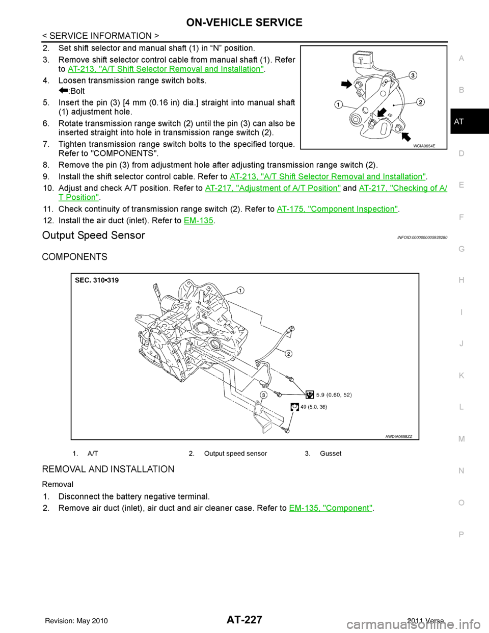
2. Set shift selector and manual shaft (1) in “N” position.
3. Remove shift selector control cable from manual shaft (1). Refer to AT-213, "
A/T Shift Selector Removal and Installation".
4. Loosen transmission range switch bolts. :Bolt
5. Insert the pin (3) [4 mm (0.16 in) dia.] straight into manual shaft (1) adjustment hole.
6. Rotate transmission range switch (2) until the pin (3) can also be inserted straight into hole in transmission range switch (2).
7. Tighten transmission range switch bolts to the specified torque. Refer to "COMPONENTS".
8. Remove the pin (3) from adjustment hole after adjusting transmission range switch (2).
9. Install the shift selector control cable. Refer to AT-213, "
A/T Shift Selector Removal and Installation".
10. Adjust and check A/T position. Refer to AT-217, "
Adjustment of A/T Position" and AT-217, "Checking of A/
T Position".
11. Check continuity of transmiss ion range switch (2). Refer to AT-175, "
Component Inspection".
12. Install the air duct (inlet). Refer to EM-135
.
Output Speed SensorINFOID:0000000005928280
COMPONENTS
REMOVAL AND INSTALLATION
Removal
1. Disconnect the battery negative terminal.
2. Remove air duct (inlet), air duct and air cleaner case. Refer to EM-135, "
Component".
WCIA0654E
1. A/T2. Output speed sensor3. Gusset
AWDIA0658ZZ
Revision: May 2010 2011 Versa
Page 2473 of 3787
![NISSAN TIIDA 2011 Service Repair Manual ENGINE ASSEMBLYEM-83
< REMOVAL AND INSTALLATION > [HR16DE]
C
D
E
F
G H
I
J
K L
M A
EM
NP
O
• If items or work required are not covered by the engine section, follow the procedures in the applica-
bl](/manual-img/5/57396/w960_57396-2472.png "NISSAN TIIDA 2011 Service Repair Manual ENGINE ASSEMBLYEM-83
< REMOVAL AND INSTALLATION > [HR16DE]
C
D
E
F
G H
I
J
K L
M A
EM
NP
O
• If items or work required are not covered by the engine section, follow the procedures in the applica-
bl")
ENGINE ASSEMBLYEM-83
< REMOVAL AND INSTALLATION > [HR16DE]
C
D
E
F
G H
I
J
K L
M A
EM
NP
O
• If items or work required are not covered by the engine section, follow the procedures in the applica-
ble sections.
• Always use the support poin t specified for lifting.
• Use either 2-pole lift type or separate type lift as best you can. If board-on type is used for unavoid-
able reasons, support at the rear axle jacking point with a transmission jack or similar tool before
starting work, in preparation for the backward shif t of center of gravity.
• For supporting points fo r lifting and jacking point at rear axle, refer to GI-38, "
Garage Jack and
Safety Stand and 2-Pole Lift".
REMOVAL
Outline
Remove the engine and the transaxle assembly from t he vehicle downward. Separate the engine and the tran-
saxle.
Preparation
1. Remove the hood assembly. Refer to BL-14, "Removal and Installation".
2. Remove the cowl top cover and cowl top extension assembly. Refer to EI-24, "
Removal and Installation".
3. Release fuel pressure. Refer to EC-499, "
Inspection".
4. Drain engine coolant from radiator. Refer to CO-11, "
Changing Engine Coolant".
CAUTION:
• Perform this step when the engine is cold.
• Never spill engine coolant on drive belt.
5. Remove the following parts. • Engine under cover. Refer to EI-15, "
Removal and Installation".
• Front road wheels and tires. Refer to WT-7, "
Adjustment".
• Front fender protector (RH and LH). Refer to EI-26, "
Removal and Installation".
• Battery and battery tray. Refer to SC-7, "
Removal and Installation".
• Drive belt. Refer to EM-14, "
Removal and Installation".
• Air duct and air cleaner case assembly. Refer to EM-25, "
Exploded View".
• Radiator hose (upper and lower). Refer to CO-16, "
Component".
• Disconnect cooling fan controller wiring harness.
• Remove coolant reservoir tank.
• Remove fan shroud and cooling fan assembly. Refer to CO-18, "
Component (Models with A/C)" or CO-
18, "Component (Models without A/C)".
Engine Room LH
1. Disconnect all connections of engine harness around the engine mounting insulator (LH), and then tem-
porarily secure the engine harness into the engine side.
CAUTION:
Protect connectors using a resin bag against foreign materials.
2. Remove ground cable at transaxle side.
3. Disconnect fuel feed hose at engine side. Refer to EM-33, "
Exploded View".
4. Disconnect EVAP purge hose and brake booster vacuum hose.
5. Disconnect heater hoses, and install plugs them to prevent engine coolant from draining. Refer to CO-16,
"Component".
6. Disconnect control linkage from transaxle. Refer to AT-213, "
A/T Shift Selector Removal and Installation"
(A/T), MT-14, "Exploded View" (M/T).
7. Disconnect the clutch tube at tr ansmission side (if equipped). Refer to CL-15, "
Removal and Installation".
Engine Room RH
1. Remove ground cable between front cover and vehicle.
2. Remove generator and generator br acket (A/C models). Refer to SC-25, "
Removal and Installation".
3. Remove A/C compressor with piping connected from t he engine. Temporarily secure it on the vehicle side
with a rope to avoid putting load on it (if equipped). Refer to MTC-78, "
Removal and Installation of Com-
pressor - HR16DE".
Vehicle Underbody
1. Remove front wheel sensor (LH and RH) for ABS from steering knuckle (if equipped). Refer to BRC-33,
"Removal and Installation" (ABS) or BRC-86, "Removal and Installation" (VDC/TCS/ABS).
Revision: May 2010 2011 Versa
Page 2843 of 3787
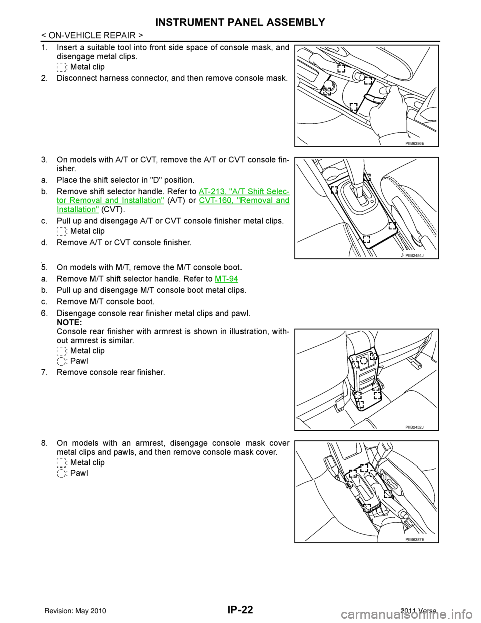
IP-22
< ON-VEHICLE REPAIR >
INSTRUMENT PANEL ASSEMBLY
1. Insert a suitable tool into front side space of console mask, anddisengage metal clips.
: Metal clip
2. Disconnect harness connector, and then remove console mask.
3. On models with A/T or CVT, remo ve the A/T or CVT console fin-
isher.
a. Place the shift selector in "D" position.
b. Remove shift selector handle. Refer to AT-213, "
A/T Shift Selec-
tor Removal and Installation" (A/T) or CVT-160, "Removal and
Installation" (CVT).
c. Pull up and disengage A/T or CVT console finisher metal clips. : Metal clip
d. Remove A/T or CVT console finisher.
4.5. On models with M/T, remove the M/T console boot.
a. Remove M/T shift selector handle. Refer to MT-94
b. Pull up and disengage M/T console boot metal clips.
c. Remove M/T console boot.
6. Disengage console rear finisher metal clips and pawl.
NOTE:
Console rear finisher with armrest is shown in illustration, with-
out armrest is similar.
: Metal clip
: Pawl
7. Remove console rear finisher.
8. On models with an armrest, disengage console mask cover metal clips and pawls, and then remove console mask cover.
: Metal clip
: Pawl
PIIB6386E
PIIB2454J
PIIB2452J
PIIB6387E
Revision: May 2010 2011 Versa