2011 NISSAN TIIDA tow
[x] Cancel search: towPage 3069 of 3787
HEADLAMP (FOR CANADA) - DAYTIME LIGHT SYSTEM -
LT-37
< SERVICE INFORMATION >
C
D E
F
G H
I
J
L
M A
B
LT
N
O P
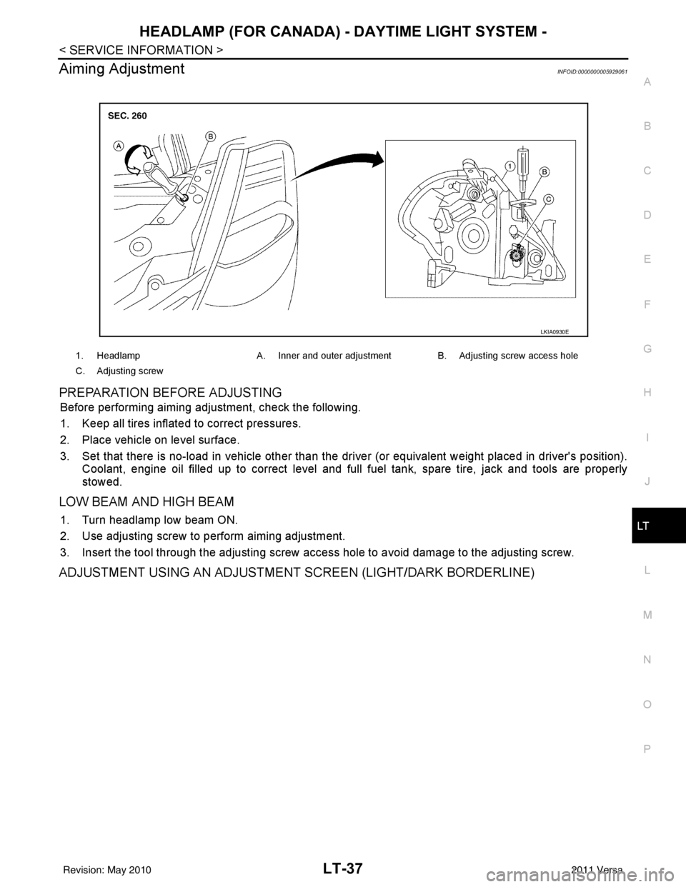
Aiming AdjustmentINFOID:0000000005929061
PREPARATION BEFORE ADJUSTING
Before performing aiming adjustment, check the following.
1. Keep all tires inflated to correct pressures.
2. Place vehicle on level surface.
3. Set that there is no-load in vehicle other than the driv er (or equivalent weight placed in driver's position).
Coolant, engine oil filled up to correct level and full fuel tank, spare tire, jack and tools are properly
stowed.
LOW BEAM AND HIGH BEAM
1. Turn headlamp low beam ON.
2. Use adjusting screw to perform aiming adjustment.
3. Insert the tool through the adjusting screw access hole to avoid damage to the adjusting screw.
ADJUSTMENT USING AN ADJUSTMENT SCREEN (LIGHT/DARK BORDERLINE)
1. Headlamp A. Inner and outer adjustment B. Adjusting screw access hole
C. Adjusting screw
LKIA0930E
Revision: May 2010 2011 Versa
Page 3071 of 3787
HEADLAMP (FOR CANADA) - DAYTIME LIGHT SYSTEM -
LT-39
< SERVICE INFORMATION >
C
D E
F
G H
I
J
L
M A
B
LT
N
O P
2. Turn bulb socket counterclockwise and unlock from front combination lamp assembly.
3. Remove bulb from its socket.
FRONT TURN SIGNAL LAMP
1. Turn lighting switch OFF.
2. Turn bulb socket counterclockwise and unlock from front combination lamp assembly.
3. Remove bulb from its socket.
Removal and InstallationINFOID:0000000005929063
REMOVAL
1. Disconnect the negative battery terminal.
2. Remove front bumper fascia. Refer to EI-15
.
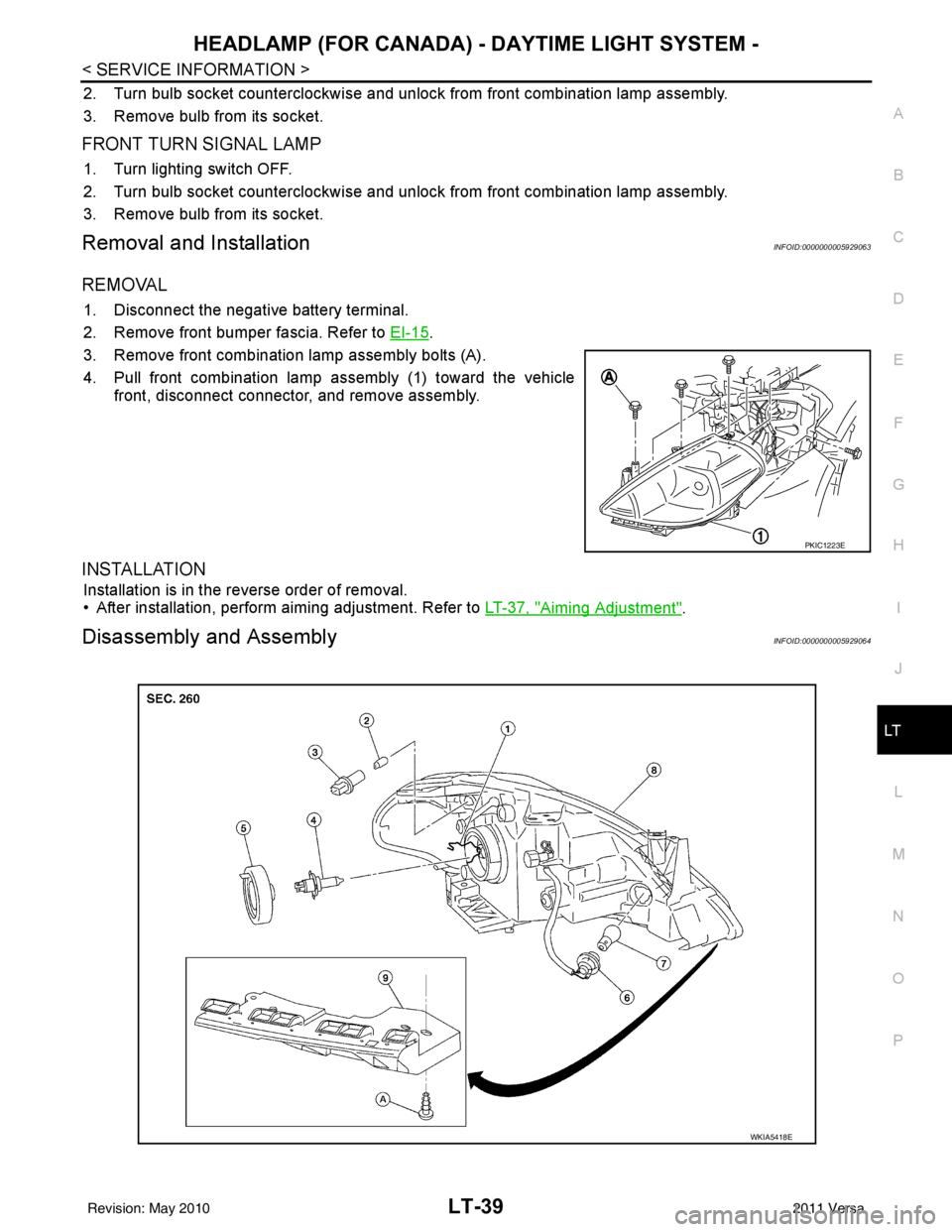
3. Remove front combination lamp assembly bolts (A).
4. Pull front combination lamp assembly (1) toward the vehicle front, disconnect connector, and remove assembly.
INSTALLATION
Installation is in the reverse order of removal.
• After installation, perform aiming adjustment. Refer to LT-37, "
Aiming Adjustment".
Disassembly and AssemblyINFOID:0000000005929064
PKIC1223E
WKIA5418E
Revision: May 2010 2011 Versa
Page 3080 of 3787
LT-48
< SERVICE INFORMATION >
FRONT FOG LAMP
1. Check continuity between front fog lamp harness connector and
ground.
OK or NG
OK >> Replace IPDM E/R. Refer to PG-28, "Removal and
Installation of IPDM E/R" .
NG >> Repair harness or connector.
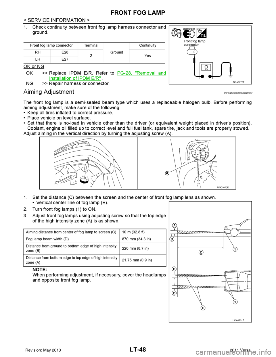
Aiming AdjustmentINFOID:0000000005929077
The front fog lamp is a semi-sealed beam type which uses a replaceable halogen bulb. Before performing
aiming adjustment, make sure of the following.
• Keep all tires inflated to correct pressure.
• Place vehicle on level surface.
• Set that there is no-load in vehicle other than the driv er (or equivalent weight placed in driver’s position).
Coolant, engine oil filled up to correct level and full fuel tank, spare tire, jack and tools are properly stowed.
Adjust aiming in the vertical direct ion by turning the adjusting screw (A).
1. Set the distance (C) between the screen and the center of front fog lamp lens as shown. • Vertical center line of fog lamp (E).
2. Turn front fog lamps (1) to ON.
3. Adjust front fog lamps using adjusting screw so that the top edge of the high intensity zone (A) is as shown.
NOTE:
When performing adjustment, if necessary, cover the headlamps
and opposite front fog lamp.
Front fog lamp connector Terminal
Ground Continuity
RH E28
2Y es
LH E27
PKIA6277E
PKIC1070E
Aiming distance from center of fog lamp to screen (C) 10 m (32.8 ft)
Fog lamp beam width (D) 870 mm (34.3 in)
Distance from ground to bottom edge of high intensity
zone (B) 220 mm (8.7 in)
Distance from bottom edge to top edge of high intensity
zone (A) 21.75 mm (0.9 in)
LKIA0931E
Revision: May 2010
2011 Versa
Page 3094 of 3787
LT-62
< SERVICE INFORMATION >
LIGHTING AND TURN SIGNAL SWITCH
LIGHTING AND TURN SIGNAL SWITCH
Removal and InstallationINFOID:0000000005929098
REMOVAL
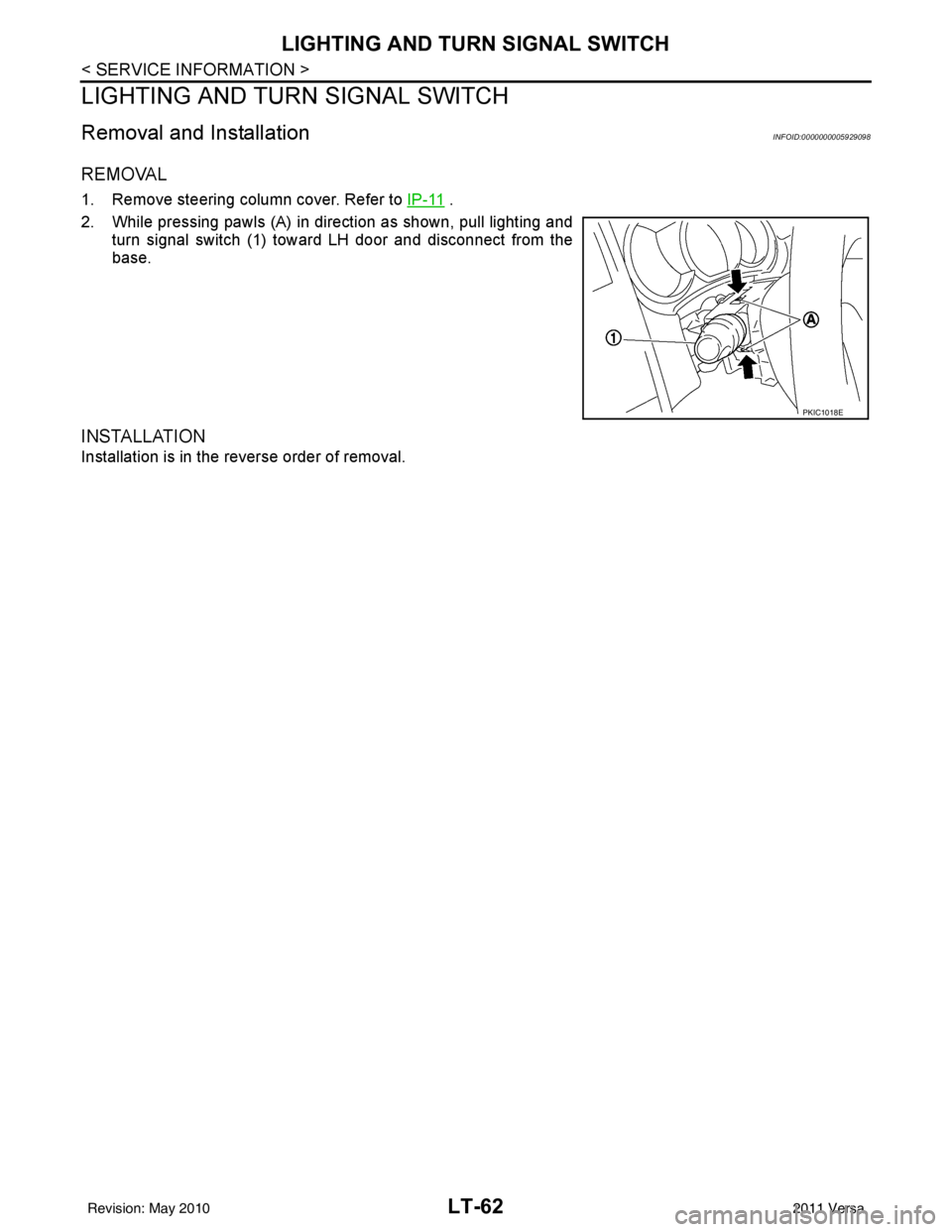
1. Remove steering column cover. Refer to IP-11 .
2. While pressing pawls (A) in direction as shown, pull lighting and turn signal switch (1) toward LH door and disconnect from the
base.
INSTALLATION
Installation is in the reverse order of removal.
PKIC1018E
Revision: May 2010 2011 Versa
Page 3120 of 3787
LT-88
< SERVICE INFORMATION >
REAR COMBINATION LAMP
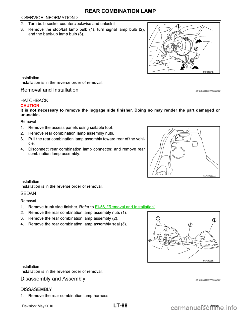
2. Turn bulb socket counterclockwise and unlock it.
3. Remove the stop/tail lamp bulb (1), turn signal lamp bulb (2),and the back-up lamp bulb (3).
Installation
Installation is in the reverse order of removal.
Removal and InstallationINFOID:0000000005929132
HATCHBACK
CAUTION:
It is not necessary to remove the luggage side finisher. Doing so may render the part damaged or
unusable.
Removal
1. Remove the access panels using suitable tool.
2. Remove rear combination lamp assembly nuts.
3. Pull the rear combination lamp assembly toward rear of the vehi-
cle.
4. Disconnect rear combination lamp connector, and remove rear combination lamp assembly.
Installation
Installation is in the reverse order of removal.
SEDAN
Removal
1. Remove trunk side finisher. Refer to EI-56, "Removal and Installation".
2. Remove the rear combination lamp assembly nuts (1).
3. Remove the rear combination lamp assembly (2).
4. Remove the rear combination lamp assembly seal (3).
Installation
Installation is in the reverse order of removal.
Disassembly and AssemblyINFOID:0000000005929133
DISSASEMBLY
1. Remove the rear combination lamp harness.
PKIC1034E
ALKIA1859ZZ
PKIC1035E
Revision: May 2010 2011 Versa
Page 3180 of 3787
PERIODIC MAINTENANCEMA-9
< SERVICE INFORMATION >
C
DE
F
G H
I
J
K
M A
B
MA
N
O P
PERIODIC MAINTENANCE
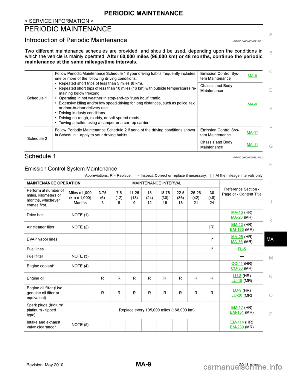
Introduction of Periodic MaintenanceINFOID:0000000005931131
Two different maintenance schedules are provi ded, and should be used, depending upon the conditions in
which the vehicle is mainly operated. After 60,000 miles (96,000 km) or 48 months, continue the periodic
maintenance at the same mileage/time intervals.
Schedule 1INFOID:0000000005931132
Emission Control System Maintenance
Abbreviations: R = Replace. I = Inspect. Correct or r eplace if necessary. [ ]: At the mileage intervals only
Schedule 1Follow Periodic Maintenance Schedule 1 if your driving habits frequently includes
one or more of the following driving conditions:
• Repeated short trips of less than 5 miles (8 km).
• Repeated short trips of less than 10 miles (16 km) with outside temperatures re-
maining below freezing.
• Operating in hot weather in stop-and-go “rush hour” traffic.
• Extensive idling and/or low speed driving for long distances, such as police, taxi
or door-to-door delivery use.
• Driving in dusty conditions.
• Driving on rough, muddy, or salt spread roads.
• Towing a trailer, using a camper or a car-top carrier. Emission Control Sys-
tem Maintenance
MA-9
Chassis and Body
Maintenance
MA-9
Schedule 2Follow Periodic Maintenance Schedule 2 if none of the driving conditions shown
in Schedule 1 apply to your driving habits.
Emission Control Sys-
tem Maintenance
MA-11Chassis and Body
Maintenance
MA-11
MAINTENANCE OPERATION
MAINTENANCE INTERVAL
Reference Section -
Page or - Content Title
Perform at number of
miles, kilometers or
months, whichever
comes first. Miles x 1,000
(km x 1,000) Months 3.75
(6)3 7.5
(12) 6 11 . 2 5
(18) 9 15
(24) 12 18.75
(30)15 22.5
(36) 18 26.25
(42)21 30
(48) 24
Drive belt NOTE (1) MA-16
(HR)
MA-26
(MR)
Air cleaner filter NOTE (2) [R]EM-13
(HR)
EM-136
(MR)
EVAP vapor lines I*MA-25
(HR)
MA-36
(MR)
Fuel lines I*FL-5
Fuel filter NOTE (3) —
Engine coolant* NOTE (4) CO-11
(HR)
CO-36
(MR)
Engine oil R R R R R R R R LU-8
(HR)
LU-18
(MR)
Engine oil filter (Use
genuine oil filter or
equivalent) RRRRRRRR
LU-9
(HR)
LU-20
(MR)
Spark plugs (Iridium/
platinum - tipped
type) Replace every 105,000 miles (168,000 km)
EM-17
(HR)
EM-151
(MR)
Intake and exhaust
valve clearance* NOTE (5) EM-114
(HR)
EM-230
(MR)
Revision: May 2010 2011 Versa
Page 3182 of 3787
PERIODIC MAINTENANCEMA-11
< SERVICE INFORMATION >
C
DE
F
G H
I
J
K
M A
B
MA
N
O P
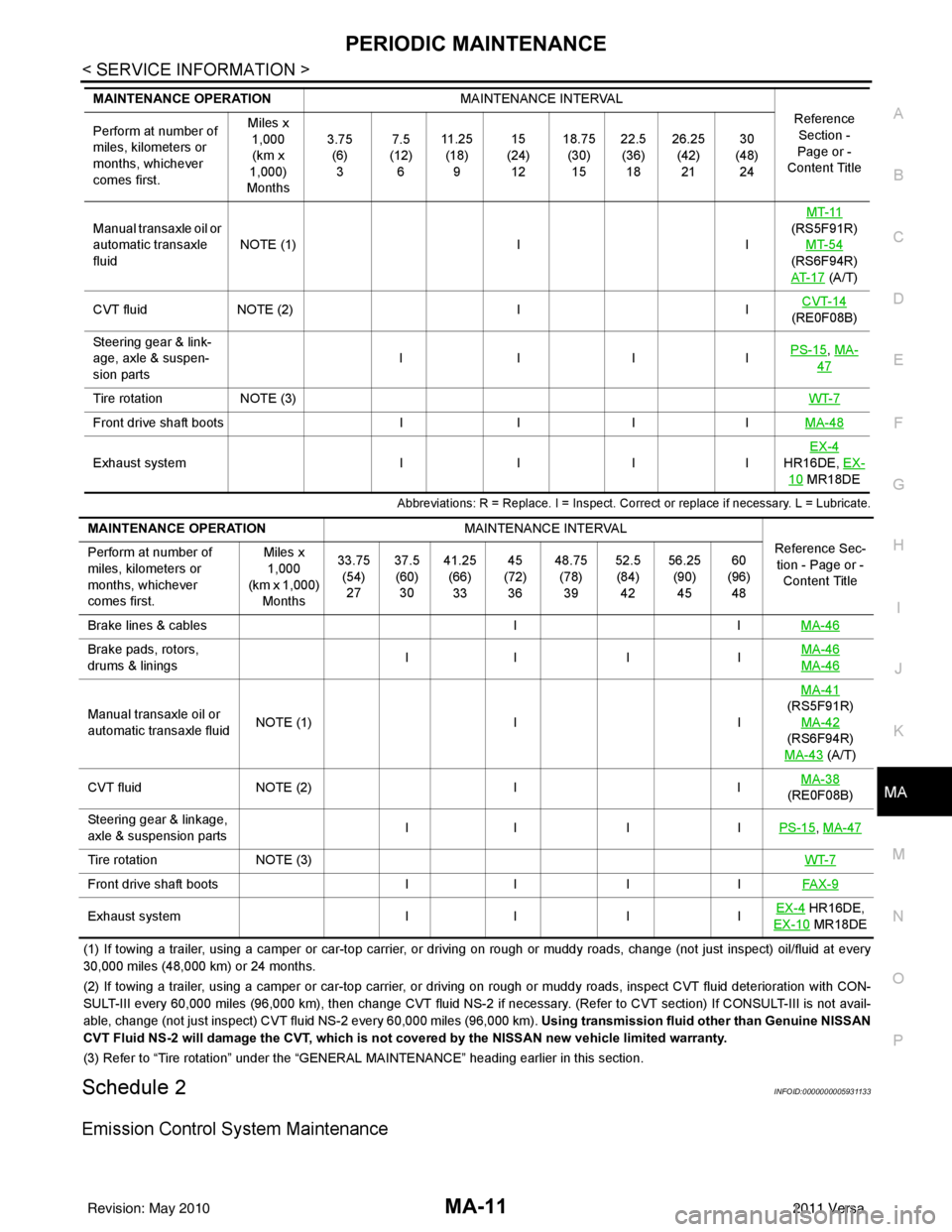
Abbreviations: R = Replace. I = Inspect. Corr ect or replace if necessary. L = Lubricate.
(1) If towing a trailer, using a camper or car-top carrier, or driving on rough or muddy roads, change (not just inspect) oil/f luid at every
30,000 miles (48,000 km) or 24 months.
(2) If towing a trailer, using a camper or car-top carrier, or driving on rough or muddy roads, inspect CVT fluid deterioration with CON-
SULT-III every 60,000 miles (96,000 km), then change CVT fluid NS -2 if necessary. (Refer to CVT section) If CONSULT-III is not avail-
able, change (not just inspect) CVT fluid NS-2 every 60,000 miles (96,000 km). Using transmission fluid other than Genuine NISSAN
CVT Fluid NS-2 will damage the CVT, which is not covered by the NISSAN new vehicle limited warranty.
(3) Refer to “Tire rotation” under the “GENERAL MAINTENANCE” heading earlier in this section.
Schedule 2INFOID:0000000005931133
Emission Control System Maintenance
Manual transaxle oil or
automatic transaxle
fluidNOTE (1)
IIMT-11
(RS5F91R) MT-54
(RS6F94R)
AT- 1 7
(A/T)
CVT fluid NOTE (2) IICVT-14
(RE0F08B)
Steering gear & link-
age, axle & suspen-
sion parts IIII
PS-15
, MA-
47
Tire rotation
NOTE (3) WT-7
Front drive shaft bootsIIIIMA-48
Exhaust system IIIIEX-4
HR16DE, EX-
10 MR18DE
MAINTENANCE OPERATION
MAINTENANCE INTERVAL
Reference Section -
Page or -
Content Title
Perform at number of
miles, kilometers or
months, whichever
comes first. Miles x
1,000
(km x
1,000)
Months 3.75
(6)3 7.5
(12) 6 11 . 2 5
(18) 9 15
(24) 12 18.75
(30)15 22.5
(36) 18 26.25
(42)21 30
(48) 24
MAINTENANCE OPERATION MAINTENANCE INTERVAL
Reference Sec-tion - Page or - Content Title
Perform at number of
miles, kilometers or
months, whichever
comes first. Miles x
1,000
(km x 1,000)
Months 33.75
(54)27 37.5
(60) 30 41.25
(66)33 45
(72) 36 48.75
(78)39 52.5
(84) 42 56.25
(90)45 60
(96) 48
Brake lines & cables IIMA-46
Brake pads, rotors,
drums & linings II I I
MA-46
MA-46
Manual transaxle oil or
automatic transaxle fluidNOTE (1)
IIMA-41
(RS5F91R)
MA-42
(RS6F94R)
MA-43
(A/T)
CVT fluid NOTE (2) IIMA-38
(RE0F08B)
Steering gear & linkage,
axle & suspension parts II I I
PS-15
, MA-47
Tire rotationNOTE (3) WT-7
Front drive shaft bootsII IIFAX-9
Exhaust system II IIEX-4 HR16DE,
EX-10
MR18DE
Revision: May 2010 2011 Versa
Page 3209 of 3787
MA-38
< SERVICE INFORMATION >
CHASSIS AND BODY MAINTENANCE
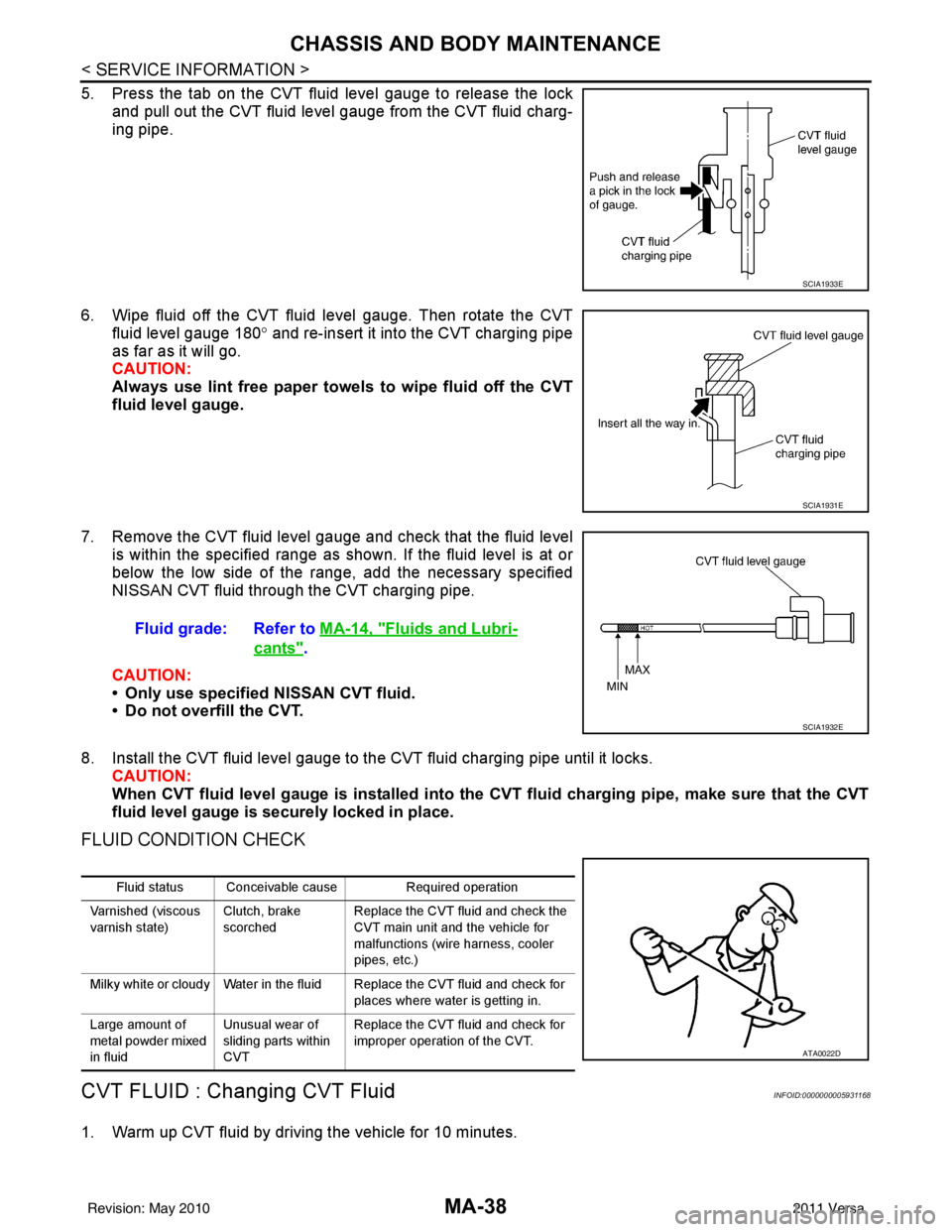
5. Press the tab on the CVT fluid level gauge to release the lockand pull out the CVT fluid level gauge from the CVT fluid charg-
ing pipe.
6. Wipe fluid off the CVT fluid level gauge. Then rotate the CVT fluid level gauge 180 ° and re-insert it into the CVT charging pipe
as far as it will go.
CAUTION:
Always use lint free paper towels to wipe fluid off the CVT
fluid level gauge.
7. Remove the CVT fluid level gauge and check that the fluid level is within the specified range as shown. If the fluid level is at or
below the low side of the range, add the necessary specified
NISSAN CVT fluid through the CVT charging pipe.
CAUTION:
• Only use specified NISSAN CVT fluid.
• Do not overfill the CVT.
8. Install the CVT fluid level gauge to the CVT fluid charging pipe until it locks. CAUTION:
When CVT fluid level gauge is in stalled into the CVT fluid charging pipe, make sure that the CVT
fluid level gauge is securely locked in place.
FLUID CONDITION CHECK
CVT FLUID : Chan ging CVT FluidINFOID:0000000005931168
1. Warm up CVT fluid by driving the vehicle for 10 minutes.
SCIA1933E
SCIA1931E
Fluid grade: Refer to MA-14, "Fluids and Lubri-
cants".
SCIA1932E
Fluid status Conceivable cause Required operation
Varnished (viscous
varnish state) Clutch, brake
scorchedReplace the CVT fluid and check the
CVT main unit and the vehicle for
malfunctions (wire harness, cooler
pipes, etc.)
Milky white or cloudy Water in the fluid Replace the CVT fluid and check for places where water is getting in.
Large amount of
metal powder mixed
in fluid Unusual wear of
sliding parts within
CVTReplace the CVT fluid and check for
improper operation of the CVT.
ATA0022D
Revision: May 2010
2011 Versa