2011 NISSAN TIIDA recommended oil
[x] Cancel search: recommended oilPage 3253 of 3787
![NISSAN TIIDA 2011 Service Repair Manual MT-32
< SERVICE INFORMATION >[RS5F91R]
TRANSAXLE ASSEMBLY
29. Install 5th-reverse fork rod (1) to clutch housing according to the
following procedures.
CAUTION:
Replace 5th-reverse fork rod and 5th-r](/manual-img/5/57396/w960_57396-3252.png "NISSAN TIIDA 2011 Service Repair Manual MT-32
< SERVICE INFORMATION >[RS5F91R]
TRANSAXLE ASSEMBLY
29. Install 5th-reverse fork rod (1) to clutch housing according to the
following procedures.
CAUTION:
Replace 5th-reverse fork rod and 5th-r")
MT-32
< SERVICE INFORMATION >[RS5F91R]
TRANSAXLE ASSEMBLY
29. Install 5th-reverse fork rod (1) to clutch housing according to the
following procedures.
CAUTION:
Replace 5th-reverse fork rod and 5th-reverse shift fork as a
set.
a. Pull gear of reverse gear assembly (2) up.
b. Temporarily install 5th-reverse fork rod to clutch housing.
c. Press gear of reverse gear assembly (1) down and then install 5th-reverse fork rod (2) to clutch housing.
CAUTION:
Set levers of 5th-reverse fork rod so as to align with reverse
gear assembly groove ( ).
30. Install 4th main gear (2) and spacer (1) to mainshaft. CAUTION:
Install spacer so that spacer protrusion faces to transaxle
rear side.
31. Press 3rd-4th shift fork down and then shift 3rd-4th coupling sleeve to 3rd gear side.
32. Shift control shaft shift lever (1) to the 3rd gear position. NOTE:
• If it is not shifted to the 3r d gear position, transaxle case can-
not be installed to clutch housing.
• The 3rd gear position means that control shaft select lever is fully rotated clockwise and it is returned approximately 10
degrees.
33. Apply recommended sealant to transaxle case mounting surface of clutch housing.
•Use Genuine Silicone RT V or an equivalent. GI-42, "
Rec-
ommended Chemical Product and Sealant".
CAUTION:
• Never allow old liquid gasket, moisture, oil, or foreign matte r to remain on mounting surface.
• Check that mounting surface is not damaged.
• Apply a continuous bead of liqu id gasket to the mounting surface.
PCIB1629E
PCIB1552E
PCIB1529E
PCIB1524E
Revision: May 2010 2011 Versa
Page 3254 of 3787
![NISSAN TIIDA 2011 Service Repair Manual TRANSAXLE ASSEMBLYMT-33
< SERVICE INFORMATION > [RS5F91R]
D
E
F
G H
I
J
K L
M A
B
MT
N
O P
34. Install transaxle case to clutch hous ing. If it is difficult to install,
slightly rotate control shaft s](/manual-img/5/57396/w960_57396-3253.png "NISSAN TIIDA 2011 Service Repair Manual TRANSAXLE ASSEMBLYMT-33
< SERVICE INFORMATION > [RS5F91R]
D
E
F
G H
I
J
K L
M A
B
MT
N
O P
34. Install transaxle case to clutch hous ing. If it is difficult to install,
slightly rotate control shaft s")
TRANSAXLE ASSEMBLYMT-33
< SERVICE INFORMATION > [RS5F91R]
D
E
F
G H
I
J
K L
M A
B
MT
N
O P
34. Install transaxle case to clutch hous ing. If it is difficult to install,
slightly rotate control shaft shift lever counterclockwise, and then
install.
•1: Selector
• 2: Shift fork
CAUTION:
• Never disrupt liquid gasket bead with transaxle case or
other objects during installation.
• Be careful to align the lever of 5th-reverse fork rod with
reverse gear assembly groove.
35. Rotate input shaft so that bearing and shaft fit each other, and then tighten transaxle bolts ( ) to the specified torque. Refer to
MT-17, "
Exploded View".
36. Apply recommended sealant to the position switch thread and check ball plug thread. tighten them to tran- saxle case to specified torque.
•Use Genuine Silicon RTV or an equivalent. Refer to GI-42, "
Recommended Chemical Product and
Sealant".
CAUTION:
Never allow old liquid gasket, moisture, oil, or foreign matter to remain on thread.
37. Apply gear oil to mainshaft spline.
38. Install 5th main gear (1) to mainshaft using a suitable bolt (A) [M10 x 1.0] and a suitable nut (B).
39. Install adapter plate (1), bushing (2), and 5th input gear (3) to input shaft.
CAUTION:
Be careful with the orientation of adapter plate.
• : Transaxle case side
40. Install 5th-reverse synchronizer hub, 5th-reverse c oupling sleeve, and 5th-reverse shift fork according to
the following procedures.
a. Apply gear oil to 5th-reverse baulk ring.
PCIB1553E
JPDIC0610ZZ
PCIB1554E
PCIB1555E
Revision: May 2010 2011 Versa
Page 3298 of 3787
![NISSAN TIIDA 2011 Service Repair Manual TRANSAXLE ASSEMBLYMT-77
< SERVICE INFORMATION > [RS6F94R]
D
E
F
G H
I
J
K L
M A
B
MT
N
O P
23. Set fork rod (1) to input shaft assembly (2), and then install them to clutch housing.
24. Install mainsh](/manual-img/5/57396/w960_57396-3297.png "NISSAN TIIDA 2011 Service Repair Manual TRANSAXLE ASSEMBLYMT-77
< SERVICE INFORMATION > [RS6F94R]
D
E
F
G H
I
J
K L
M A
B
MT
N
O P
23. Set fork rod (1) to input shaft assembly (2), and then install them to clutch housing.
24. Install mainsh")
TRANSAXLE ASSEMBLYMT-77
< SERVICE INFORMATION > [RS6F94R]
D
E
F
G H
I
J
K L
M A
B
MT
N
O P
23. Set fork rod (1) to input shaft assembly (2), and then install them to clutch housing.
24. Install mainshaft assembly (1) according to the following proce- dures.
a. Pull up input shaft assembly (2) and fork rod (3).
b. Set 1st-2nd fork rod (4) to mainshaft assembly, and then install them to clutch housing.
25. Install reverse idler shaft assembly (1) according to the following procedures.
a. Install spring washer to clutch housing.
b. Pull up input shaft assembly (2), mainshaft assembly (3), fork rod (4), and 1st-2nd fork rod (5).
NOTE:
It is easier to pull up when shifting each fork rod to each shaft
side.
c. Set reverse fork rod (6) to reverse idler shaft assembly, and then install them to clutch housing.
26. Shift 1st-2nd fork rod (1), fork rod (2), and reverse fork rod (3) to the neutral position.
27. Install selector (4) to clutch housing. CAUTION:
Replace selector lever and selector as a set.
28. Install selector spring (1) to return bushing (A).
29. Apply recommended sealant to transaxle case mounting sur- face.
•Use Genuine Liquid Gasket, Three Bond 1215 or an equiv-
alent.
CAUTION:
• Never allow old liquid gasket, moisture, oil, or foreign
matter to remain on mounting surface.
• Check that mounting surface is not damaged.
• Apply liquid gasket bead continuously.
JPDIC0608ZZ
JPDIC0609ZZ
JPDIC0606ZZ
SCIA7782E
JPDIC0445ZZ
Revision: May 2010 2011 Versa
Page 3299 of 3787
![NISSAN TIIDA 2011 Service Repair Manual MT-78
< SERVICE INFORMATION >[RS6F94R]
TRANSAXLE ASSEMBLY
30. Install transaxle case to clutch housing while rotating shifter
lever A (1) in the direction as shown.
31. Install reverse idler shaft bol](/manual-img/5/57396/w960_57396-3298.png "NISSAN TIIDA 2011 Service Repair Manual MT-78
< SERVICE INFORMATION >[RS6F94R]
TRANSAXLE ASSEMBLY
30. Install transaxle case to clutch housing while rotating shifter
lever A (1) in the direction as shown.
31. Install reverse idler shaft bol")
MT-78
< SERVICE INFORMATION >[RS6F94R]
TRANSAXLE ASSEMBLY
30. Install transaxle case to clutch housing while rotating shifter
lever A (1) in the direction as shown.
31. Install reverse idler shaft bolt ( ) according to the following pro- cedures.
a. Install seal washer to reverse idler shaft mounting bolt, and install reverse idler shaft bolt to transaxle case.
CAUTION:
Never reuse seal washer.
b. Tighten reverse idler shaft bolt to the specified torque. Refer to MT-62, "
Disassembly and Assembly".
32. Tighten transaxle case bolts ( ) to the specified torque. Refer to MT-62, "
Disassembly and Assembly".
33. Install position switch (1) according to the following procedures.
a. Apply recommended sealant to position switch thread. •Use Genuine Liquid Gasket, Th ree Bond 1215 or an equiv-
alent.
CAUTION:
Never allow old liquid gasket, moisture, oil, or foreign mat-
ter to remain on thread.
b. Install position switch to transaxle case, and tighten it to the specified torque. Refer to MT-62, "
Disassembly and Assembly".
34. Install bracket (2) to transaxle case, and tighten mounting bolt to the specified torque. Refer to MT-62, "
Disassembly and Assem-
bly".
35. Install selector lever (3) according to following the procedures.
a. Install selector lever to transaxle case. CAUTION:
Replace selector lever and selector as a set.
b. Install retaining pin to selector lever, using a suitable tool. CAUTION:
Never reuse retaining pin.
36. Install drain plug according to the following procedures.
a. Install gasket to drain plug. CAUTION:
JPDIC0110ZZ
PCIB1695E
PCIB1694E
SCIA7784E
Revision: May 2010 2011 Versa
Page 3324 of 3787
MTC-8
< SERVICE INFORMATION >
PRECAUTIONS
Precaution for Service of Compressor
INFOID:0000000005930830
• Plug all openings to prevent moisture and foreign matter from entering.
• When the compressor is removed, store it in th e same position as it is when mounted on the car.
• When replacing or repairing compressor, follow “Maintenance of Oil Quantity in Compressor”
exactly. Refer to MTC-17, "
Maintenance of Oil Quantity in Compressor".
• Keep friction surfaces between clut ch and pulley clean. If the surface is contaminated, with oil, wipe
it off by using a clean waste cloth moistened with thinner.
• After compressor service operation, turn the compresso r shaft by hand more than five turns in both
directions. This will equally distribute oil inside the compressor. After the compressor is installed,
let the engine idle and operate the compressor for one hour.
• After replacing the compressor magnet clutch, ap ply voltage to the new one and check for usual
operation.
Precaution for Service EquipmentINFOID:0000000005930831
RECOVERY/RECYCLING EQUIPMENT
Be certain to follow the manufacturer’s instructions for machine operation and machine maintenance. Never
introduce any refrigerant other than that specified into the machine.
ELECTRONIC LEAK DETECTOR
Be certain to follow the manufacturer’s instruct ions for tester operation and tester maintenance.
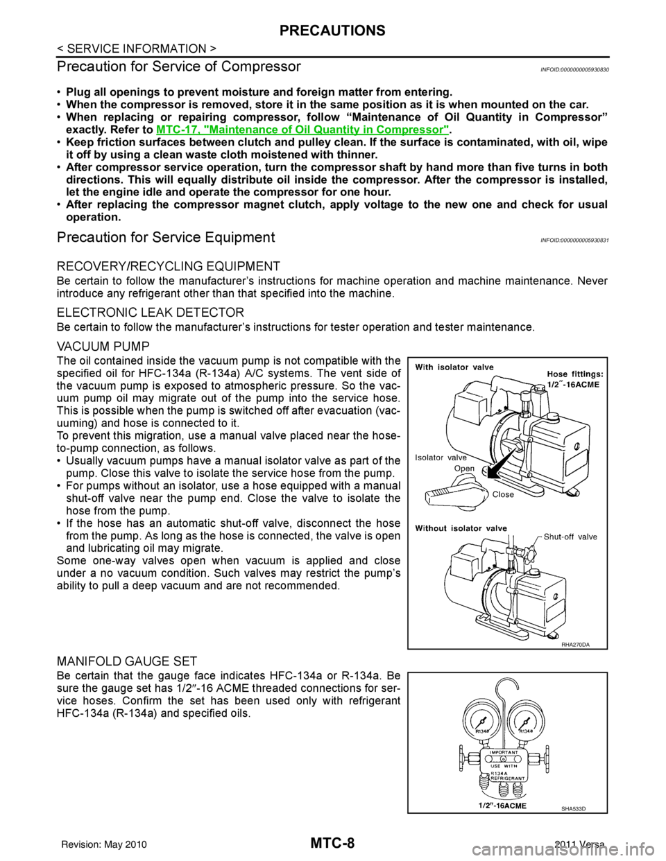
VACUUM PUMP
The oil contained inside the vacuum pump is not compatible with the
specified oil for HFC-134a (R-134a) A/C systems. The vent side of
the vacuum pump is exposed to atmospheric pressure. So the vac-
uum pump oil may migrate out of the pump into the service hose.
This is possible when the pump is switched off after evacuation (vac-
uuming) and hose is connected to it.
To prevent this migration, use a manual valve placed near the hose-
to-pump connection, as follows.
• Usually vacuum pumps have a manual isolator valve as part of the pump. Close this valve to isolat e the service hose from the pump.
• For pumps without an isolator, use a hose equipped with a manual shut-off valve near the pump end. Close the valve to isolate the
hose from the pump.
• If the hose has an automatic shut -off valve, disconnect the hose
from the pump. As long as the hose is connected, the valve is open
and lubricating oil may migrate.
Some one-way valves open when vacuum is applied and close
under a no vacuum condition. Such valves may restrict the pump’s
ability to pull a deep vacuum and are not recommended.
MANIFOLD GAUGE SET
Be certain that the gauge face indicates HFC-134a or R-134a. Be
sure the gauge set has 1/2 ″-16 ACME threaded connections for ser-
vice hoses. Confirm the set has been used only with refrigerant
HFC-134a (R-134a) and specified oils.
RHA270DA
SHA533D
Revision: May 2010 2011 Versa
Page 3559 of 3787

RSU-6
< SERVICE INFORMATION >
REAR SUSPENSION ASSEMBLY
REAR SUSPENSION ASSEMBLY
On-Vehicle Inspection and ServiceINFOID:0000000005931084
Make sure the mounting conditions (looseness, backlash) of each component and component conditions
(wear, damage) are within specifications.
SHOCK ABSORBER INSPECTION
Check shock absorber for oil leakage, damage and replace it if necessary.
Wheel AlignmentInspectionINFOID:0000000005931085
DESCRIPTION
Measure wheel alignment under unladen conditions.
NOTE:
“Unladen conditions” means that fuel, engine coolant, and lubricant are full. Spare tire, jack, hand tools and
mats are in designated positions.
PRELIMINARY
Check the following:
1. Tires for improper air pressure and wear.
2. Road wheels for runout. Refer to WT-6
.
3. Wheel bearing axial end play. Refer to RAX-6, "
On-Vehicle Inspection and Service" .
4. Shock absorber operation.
5. Each mounting part of suspension for looseness and deformation.
6. Rear suspension beam for cracks, deformation, and other damage.
7. Vehicle height (posture).
GENERAL INFORMATION AND RECOMMENDATIONS
1. A Four-Wheel Thrust Alignment should be performed. • This type of alignment is recommended for any NISSAN vehicle.
• The four-wheel “thrust” process helps ensure that the vehicle is properly aligned and the steering wheel
is centered.
• The alignment machine itself should be ca pable of accepting any NISSAN vehicle.
• The alignment machine should be checked to ensure that it is level.
2. Make sure the alignment machine is properly calibrated. • Your alignment machine should be regularly calibrated in order to give correct information.
• Check with the manufacturer of your specific al ignment machine for their recommended Service/Cali-
bration Schedule.
THE ALIGNMENT PROCESS
IMPORTANT: Use only the alignment specifications listed in this Service Manual. Refer to RSU-13, "Wheel
Alignment (Unladen*)" .
1. When displaying the alignment settings, many alignment machines use “indicators”: (Green/red, plus or minus, Go/No Go). Do NOT use these indicators.
• The alignment specifications programmed into your alignment machine that operate these indicators may not be correct.
• This may result in an ERROR.
2. Some newer alignment machines are equipped with an optional “Rolling Compensation” method to “com- pensate” the sensors (alignment targets or head units). Do NOT use this “Rolling Compensation”
method.
• Use the “Jacking Compensation” method. After inst alling the alignment targets or head units, raise the
vehicle and rotate the wheels 1/2 turn both ways.
• See Instructions in the alignment machine you are using for more information.
CAMBER INSPECTION
Revision: May 2010 2011 Versa