2011 NISSAN TIIDA horn
[x] Cancel search: hornPage 3463 of 3787
HARNESSPG-43
< SERVICE INFORMATION >
C
DE
F
G H
I
J
L
M A
B
PG
N
O P
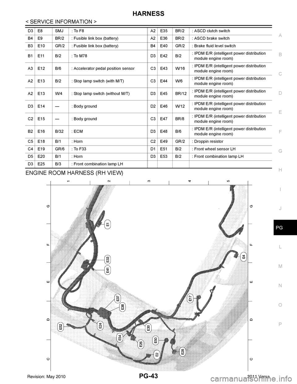
ENGINE ROOM HARNESS (RH VIEW)
D3 E8 SMJ : To F8 A2 E35 BR/2 : ASCD clutch switch
B4 E9 BR/2 : Fusible link box (battery) A2 E36 BR/2 : ASCD brake switch
B3 E10 GR/2 : Fusible link box (battery) B4 E40 GR/2 : Brake fluid level switch
B1 E11 B/2 : To M78 D3 E42 B/2: IPDM E/R (intelligent power distribution
module engine room)
A3 E12 B/6 : Accelerator pedal position sensor C3 E43 W/16 : IPDM E/R (intelligent power distribution
module engine room)
A2 E13 B/2 : Stop lamp switch (with M/T) C3 E44 W/6: IPDM E/R (intelligent power distribution
module engine room)
A2 E13 W/4 : Stop lamp switch (without M/T) D3 E45 BR/12: IPDM E/R (intelligent power distribution
module engine room)
D3 E14 — : Body ground D2 E46 W/12: IPDM E/R (intelligent power distribution
module engine room)
C2 E15 — : Body ground C3 E47 BR/8: IPDM E/R (intelligent power distribution
module engine room)
B2 E16 B/32 : ECM D3 E48 B/6: IPDM E/R (intelligent power distribution
module engine room)
C5 E18 B/1 : Horn C2 E49 GR/2 : Droppin resistor
C4 E19 GR/6 : To F33 D1 E51 B/2 : Front wheel sensor LH
D5 E20 B/1 : Horn D3 E53 B/2 : Front combination lamp LH
D3 E25 B/3 : Front combination lamp LH
Revision: May 2010 2011 Versa
Page 3479 of 3787

HARNESSPG-59
< SERVICE INFORMATION >
C
DE
F
G H
I
J
L
M A
B
PG
N
O P
H/LAMP LT Headlamp
H/PHON AV Hands Free Telephone
HORN WW Horn
HO2S2 EC Heated Oxygen Sensor 2
HO2S2H EC Heated Oxygen Sensor 2 Heater
IATS EC Intake Air Temperature Sensor
IGNSYS EC Ignition System
I/KEY BL Intelligent Key System
ILL LT Illumination
INJECT EC Injector
INT/L LT Room/Map, Vanity and Luggage Lamps
IVC EC Intake Valve Timing Control Solenoid Valve
KEYLES BL Remote Keyless Entry System
KS EC Knock Sensor
LPSV AT Line Pressure Solenoid Valve
LPSV CVT Line Pressure Solenoid Valve
L/USSV CVT Lock-up Select Solenoid Valve
MAFS EC Mass Air Flow Sensor
MAIN AT Main Power Supply and Ground Circuit
MAIN EC Main Power Supply and Ground Circuit
METER DI Speedometer, Tachometer, Temp. and Fuel Gauges
MIL/DL EC Malfunction Indicator Lamp
MIRROR GW Door Mirror
NATS BL Nissan Anti-Theft System
NONDTC AT Non-detectable Item
NONDTC CVT Non-detectable Item
ODSW CVT Overdrive Control Switch
OVRCSV AT Over Run Clutch Solenoid Valve
P/SCKT WW Power Socket
PGC/V EC EVAP Canister Purge Vo lume Control Solenoid Valve
PHASE EC Camshaft Position Sensor (PHASE)
PNP/SW EC Park/Neutral Position Switch
POS EC Crankshaft Position Sensor (POS)
POWER CVT Transmission Control Module (Power Supply)
PRE/SE EC EVAP Control System Pressure Sensor
PRIPS CVT Primary Pressure Sensor
PRSCVT CVT Primary Speed Sensor CVT (Input Speed Sensor)
PT/SEN AT Powertrain Revolution Sensor
RP/SEN EC Refrigerant Pressure Sensor
SECPS CVT Secondary Pressure Sensor
SECPSV CVT Secondary Speed Sensor CVT (Input Speed Sensor)
SEN/PW EC Sensor Power Supply
SESCVT CVT Secondary Pressure Sensor Solenoid Valve
SHIFT AT A/T Shift Lock System
SHIFT CVT CVT Shift Lock System
SROOF RF Sunroof
SRS SRS Supplemental Restraint System
SSV/A AT Shift Solenoid Valve A
SSV/B AT Shift Solenoid Valve B
START SC Starting System
STM CVT Step Motor
STOP/L LT Stop Lamp
Revision: May 2010 2011 Versa
Page 3669 of 3787
DRIVER AIR BAG MODULESRS-35
< ON-VEHICLE REPAIR >
C
DE
F
G
I
J
K L
M A
B
SRS
N
O P
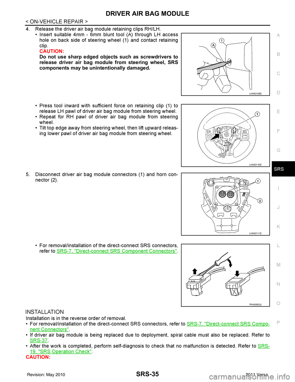
4. Release the driver air bag module retaining clips RH/LH. • Insert suitable 4mm - 6mm blunt tool (A) through LH accesshole on back side of steering wheel (1) and contact retaining
clip.
CAUTION:
Do not use sharp edged objects such as screwdrivers to
release driver air bag module from steering wheel, SRS
components may be unintentionally damaged.
• Press tool inward with sufficient force on retaining clip (1) to release LH pawl of driver air bag module from steering wheel.
• Repeat for RH pawl of driver air bag module from steering wheel.
• Tilt top edge away from steeri ng wheel, then lift upward releas-
ing lower pawl of driver air bag module from steering wheel.
5. Disconnect driver air bag module connectors (1) and horn con- nector (2).
• For removal/installation of the direct-connect SRS connectors,refer to SRS-7, "
Direct-connect SRS Component Connectors".
INSTALLATION
Installation is in the reverse order of removal.
• For removal/installation of the direct-connect SRS connectors, refer to SRS-7, "
Direct-connect SRS Compo-
nent Connectors".
• If driver air bag module is being replaced due to deploym ent, spiral cable must also be replaced. Refer to
SRS-37
.
• After the work is completed, perform self-diagnosis to check that no malfunction is detected. Refer to SRS-
19, "SRS Operation Check".
CAUTION:
LHIA0109E
LHIA0110E
LHIA0111E
PHIA0953J
Revision: May 2010 2011 Versa
Page 3747 of 3787

WW-1
ELECTRICAL
C
DE
F
G H
I
J
L
M
SECTION WW
A
B
WW
N
O P
CONTENTS
WIPER, WASHER & HORN
SERVICE INFORMATION .. ..........................2
PRECAUTION ................................................ .....2
Precaution for Supplemental Restraint System
(SRS) "AIR BAG" and "SEAT BELT PRE-TEN-
SIONER" ............................................................. ......
2
Precaution Necessary for Steering Wheel Rota-
tion After Battery Disconnect ............................... ......
2
Precaution for Procedure without Cowl Top Cover ......3
PREPARATION ...................................................4
Special Service Tool ........................................... ......4
FRONT WIPER AND WASHER SYSTEM ..........5
Component Parts and Harness Connector Loca-
tion ...................................................................... ......
5
System Description ...................................................5
CAN Communication System Description .................7
Schematic .................................................................8
Wiring Diagram - WIPER - ........................................9
Terminal and Reference Value for BCM .................12
Terminal and Reference Value for IPDM E/R .........12
How to Proceed with Trouble Diagnosis .................12
Preliminary Check ...................................................12
CONSULT-III Function (BCM) .................................12
CONSULT-III Function (IPDM E/R) .........................13
Front Wiper Does Not Operate ...............................14
Front Wiper Does Not Return to Stop Position (Af-
ter Front Wiper Operates for 10 Seconds, They
Stop for 20 Seconds, and After Repeating the Op-
eration Five Times, They Become Inoperative) ......
16
Only Front Wiper Low Does Not Operate ...............17
Only Front Wiper High Does Not Operate ...............18
Only Front Wiper Intermittent Does Not Operate ....19
Front Wiper Intermittent Operation Switch Posi-
tion Cannot Be Adjusted .........................................
20
Wiper Does Not Wipe When Front Washer Oper-
ates .........................................................................
20
Front Wiper Does Not Stop .....................................20
Removal and Installation of Front Wiper Arms ........20
Adjustment of Wiper Arm Stop Location .............. ....21
Removal and Installation of Front Wiper Drive As-
sembly .....................................................................
22
Removal and Installation of Front Washer Nozzle ....22
Inspection for Washer Nozzle ..................................23
Washer Nozzle Adjustment ................................. ....24
Washer Tube Layout ...............................................24
Removal and Installation of Front Wiper and
Washer Switch .........................................................
25
Inspection of Front Wiper and Washer Switch Cir-
cuit ...........................................................................
25
Removal and Installation of Washer Tank ...............25
Removal and Installation of Front Washer Motor ....26
REAR WIPER AND WASHER SYSTEM ..........27
Component Parts and Harness Connector Loca-
tion ....................................................................... ....
27
System Description ..................................................27
Wiring Diagram - WIP/R - ........................................29
Terminal and Reference Value for BCM ..................31
How to Proceed with Trou ble Diagnosis ..................31
Preliminary Check ............................................... ....31
CONSULT-III Function (BCM) .................................31
Rear Wiper Does Not Operate ............................ ....31
Rear Wiper Stop Position Is Incorrect .....................33
Only Rear Wiper Does Not Operate ........................34
Only Rear Wiper Intermittent Does Not Operate .....34
Wiper Does Not Wipe When Rear Washer Oper-
ates ..........................................................................
34
Removal and Installation .........................................34
Washer Nozzle Adjustment .....................................37
POWER SOCKET .............................................38
Wiring Diagram - P/SCKT - .....................................38
Removal and Installation .........................................38
HORN ................................................................40
Wiring Diagram - HORN - ........................................40
Removal and Installation .........................................40
Revision: May 2010 2011 Versa
Page 3786 of 3787
WW-40
< SERVICE INFORMATION >
HORN
HORN
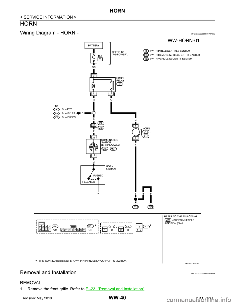
Wiring Diagram - HORN -INFOID:0000000005929252
Removal and InstallationINFOID:0000000005929253
REMOVAL
1. Remove the front grille. Refer to EI-23, "Removal and Installation".
ABLWA1011GB
Revision: May 2010 2011 Versa
Page 3787 of 3787
HORN
WW-41
< SERVICE INFORMATION >
C
D E
F
G H
I
J
L
M A
B
WW
N
O P
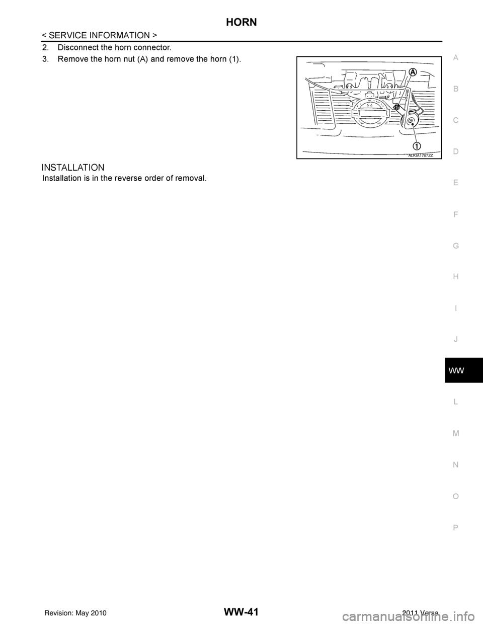
2. Disconnect the horn connector.
3. Remove the horn nut (A) and remove the horn (1).
INSTALLATION
Installation is in the reverse order of removal.
ALKIA1767ZZ
Revision: May 2010 2011 Versa