2011 NISSAN TIIDA cool fan component diagnosis
[x] Cancel search: cool fan component diagnosisPage 1754 of 3787
![NISSAN TIIDA 2011 Service Repair Manual EC-460
< COMPONENT DIAGNOSIS >[HR16DE]
REFRIGERANT PRESSURE SENSOR
REFRIGERANT PRESSURE SENSOR
DescriptionINFOID:0000000005930146
The refrigerant pressure sensor is installed at the condenser of the a](/manual-img/5/57396/w960_57396-1753.png "NISSAN TIIDA 2011 Service Repair Manual EC-460
< COMPONENT DIAGNOSIS >[HR16DE]
REFRIGERANT PRESSURE SENSOR
REFRIGERANT PRESSURE SENSOR
DescriptionINFOID:0000000005930146
The refrigerant pressure sensor is installed at the condenser of the a")
EC-460
< COMPONENT DIAGNOSIS >[HR16DE]
REFRIGERANT PRESSURE SENSOR
REFRIGERANT PRESSURE SENSOR
DescriptionINFOID:0000000005930146
The refrigerant pressure sensor is installed at the condenser of the air conditioner system. The sensor uses an
electrostatic volume pressure transducer to convert refrigerant pressure to voltage. The voltage signal is sent
to ECM, and ECM controls cooling fan system.
Component Function CheckINFOID:0000000005930147
1.CHECK REFRIGERANT PRESSURE SENSOR OVERALL FUNCTION
1. Start engine and warm it up to normal operating temperature.
2. Turn A/C switch and blower fan switch ON.
3. Check the voltage between ECM harness connector and ground.
Is the inspection result normal?
YES >> INSPECTION END
NO >> Go to EC-461, "
Diagnosis Procedure".
PBIB2657E
ECM Ground Voltage
Connector Terminal
F11 41
(Refrigerant pressure sensor signal) Ground 1.0 - 4.0V
PBIA9574J
Revision: May 2010
2011 Versa
Page 1996 of 3787
![NISSAN TIIDA 2011 Service Repair Manual EC-702
< SERVICE INFORMATION >[MR18DE]
DTC P0128 THERMOSTAT FUNCTION
DTC P0128 THERMOSTAT FUNCTION
On Board Diagn
osis LogicINFOID:0000000006341854
NOTE:
If DTC P0128 is displayed with DTC P0300, P03](/manual-img/5/57396/w960_57396-1995.png "NISSAN TIIDA 2011 Service Repair Manual EC-702
< SERVICE INFORMATION >[MR18DE]
DTC P0128 THERMOSTAT FUNCTION
DTC P0128 THERMOSTAT FUNCTION
On Board Diagn
osis LogicINFOID:0000000006341854
NOTE:
If DTC P0128 is displayed with DTC P0300, P03")
EC-702
< SERVICE INFORMATION >[MR18DE]
DTC P0128 THERMOSTAT FUNCTION
DTC P0128 THERMOSTAT FUNCTION
On Board Diagn
osis LogicINFOID:0000000006341854
NOTE:
If DTC P0128 is displayed with DTC P0300, P0301, P0302, P0303 or P 0304, first perform the trouble
diagnosis for DTC P0300, P0301, P0302, P0303, P0304. Refer to EC-783, "
DTC Confirmation Proce-
dure".
Engine coolant temperature has not risen enough to open the thermostat even though the engine has run long
enough. This is due to a leak in the seal or the thermostat stuck open.
DTC Confirmation ProcedureINFOID:0000000006341855
WITH CONSULT-III
CAUTION:
Always drive vehicle at a safe speed.
NOTE:
If DTC Confirmation Procedure has been previously conducted, always turn ignition switch OFF and wait at
least 10 seconds before conducting the next test.
TESTING CONDITION:
•For best results, perform at ambient temperature of –10 °C (14° F) or higher.
• For best results, perform at en gine coolant temperature of –10 °C (14° F) to 53 °C (127 °F).
• Before performing the following procedure, do not fill with the fuel.
1. Turn A/C switch OFF.
2. Turn blower fan switch OFF.
3. Turn ignition switch ON.
4. Select “COOLAN TEMP/S” in “DATA MONITOR” mode with CONSULT-III.
5. Check the indication of “COOLAN TEMP/S”. If it is below 53 °C (127° F), go to following step.
If it is above 53 °C (127° F), cool down the engine to less than 53 °C (127° F). Then go to next steps.
6. Start engine.
7. Drive vehicle for 10 consecutive minutes under the following conditions.
If “COOLAN TEMP/S” increases to more than 75 °C (167° F) within 10 minutes, turn ignition switch
OFF because the test result will be OK.
8. Check 1st trip DTC.
9. If 1st trip DTC is detected, go to EC-702, "
Diagnosis Procedure".
WITH GST
Follow the procedure “With CONSULT-III” above.
Diagnosis ProcedureINFOID:0000000006341856
1.CHECK ENGINE COOLANT TEMPERATURE SENSOR
Refer to EC-703, "
Component Inspection".
OK or NG
OK >> GO TO 2.
NG >> Replace engine coolant temperature sensor.
2.CHECK THERMOSTAT
DTC No. Trouble diagnosis name DTC detecting condition Possible cause
P0128
0128 Thermostat function The engine coolant temperature does not
reach to specified temperature even though
the engine has run long enough. • Thermostat
• Leakage from sealing portion of thermostat
• Engine coolant temperature sensor
VHCL SPEED SE
More than 56 km/h (35 MPH)
Revision: May 2010 2011 Versa
Page 2207 of 3787
![NISSAN TIIDA 2011 Service Repair Manual DTC P1217 ENGINE OVER TEMPERATUREEC-913
< SERVICE INFORMATION > [MR18DE]
C
D
E
F
G H
I
J
K L
M A
EC
NP
O
Cooling Fan Relay Operation
The ECM controls cooling fan relays in the IPDM E/R through CAN com](/manual-img/5/57396/w960_57396-2206.png "NISSAN TIIDA 2011 Service Repair Manual DTC P1217 ENGINE OVER TEMPERATUREEC-913
< SERVICE INFORMATION > [MR18DE]
C
D
E
F
G H
I
J
K L
M A
EC
NP
O
Cooling Fan Relay Operation
The ECM controls cooling fan relays in the IPDM E/R through CAN com")
DTC P1217 ENGINE OVER TEMPERATUREEC-913
< SERVICE INFORMATION > [MR18DE]
C
D
E
F
G H
I
J
K L
M A
EC
NP
O
Cooling Fan Relay Operation
The ECM controls cooling fan relays in the IPDM E/R through CAN communication line.
CONSULT-III Reference Val
ue in Data Monitor ModeINFOID:0000000006342101
Specification data are reference values.
On Board Diagnosis LogicINFOID:0000000006342102
If the cooling fan or another component in the cooli ng system malfunctions, engine coolant temperature will
rise. When the engine coolant temperature reaches an abnormally high temperature condition, a malfunction
is indicated.
This self-diagnosis has the on e trip detection logic.
CAUTION:
When a malfunction is in dicated, be sure to replace the coolant. Refer to MA-27, "
ENGINE COOLANT :
Changing Engine Coolant". Also, replace the engine oil. Refer to MA-32, "ENGINE OIL : Changing
Engine Oil".
1. Fill radiator with coolant up to specified level with a filling speed of 2 liters per minute. Be sure to
use coolant with the proper mixture ratio. Refer to MA-15, "
Anti-freeze Coolant Mixture Ratio".
2. After refilling coolant, run engine to ensure that no water-flow noise is emitted.
Overall Function CheckINFOID:0000000006342103
Use this procedure to check the overall function of the cooling fan. During this check, a DTC might not be con-
firmed.
WARNING:
Cooling fan speed Cooling fan relay
123
Stop (OFF) OFFOFFOFF
Low (LOW) ONOFF OFF
High (HI) ONONON
Monitor item Condition Specification
AIR COND SIG • Engine: After warming up, idle
the engine Air conditioner switch: OFF
OFF
Air conditioner switch: ON
(Compressor operates.) ON
COOLING FAN • Engine: After warming up, idle
the engine
• Air conditioner switch: OFF Engine coolant temperature: 97
°C
(207 °F) or less OFF
Engine coolant temperature: Between
98 °C (208 °F) and 99° C (210°F) LOW
Engine coolant temperature: 100 °C
(212 °F) or more HIGH
DTC No. Trouble diagnosis name
DTC detecting conditionPossible cause
P1217
1217 Engine over temperature
(Overheat) • Cooling fan does not operate properly (Over-
heat).
• Cooling fan system does not operate properly (Overheat).
• Engine coolant was not added to the system using the proper filling method.
• Engine coolant is not within the specified
range. • Harness or connectors
(Cooling fan circuit is open or shorted.)
• Cooling fan
• IPDM E/R (Cooling fan relays)
•Radiator hose
•Radiator
• Reservoir tank
•Radiator cap
• Water pump
•Thermostat
• Water control valve
For more information, refer to EC-919,
"Main 13 Causes of Overheating".
Revision: May 2010 2011 Versa
Page 2213 of 3787
![NISSAN TIIDA 2011 Service Repair Manual DTC P1217 ENGINE OVER TEMPERATUREEC-919
< SERVICE INFORMATION > [MR18DE]
C
D
E
F
G H
I
J
K L
M A
EC
NP
O
Cooling fan motor terminal 2 and IPDM E/R terminal 24.
Cooling fan motor terminal 3 and IPDM E/](/manual-img/5/57396/w960_57396-2212.png "NISSAN TIIDA 2011 Service Repair Manual DTC P1217 ENGINE OVER TEMPERATUREEC-919
< SERVICE INFORMATION > [MR18DE]
C
D
E
F
G H
I
J
K L
M A
EC
NP
O
Cooling fan motor terminal 2 and IPDM E/R terminal 24.
Cooling fan motor terminal 3 and IPDM E/")
DTC P1217 ENGINE OVER TEMPERATUREEC-919
< SERVICE INFORMATION > [MR18DE]
C
D
E
F
G H
I
J
K L
M A
EC
NP
O
Cooling fan motor terminal 2 and IPDM E/R terminal 24.
Cooling fan motor terminal 3 and IPDM E/R terminal 23.
Cooling fan motor terminal 4 and ground.
Refer to wiring diagram.
3. Also check harness for short to ground and short to power.
OK or NG
OK >> GO TO 15.
NG >> GO TO 14.
14.DETECT MALFUNCTIONING PART
Check the following.
• Harness for open or short between cooling fan motor and IPDM E/R
• Harness for open or short between cooling fan motor and ground
>> Repair open circuit or short to ground or short to power in harness or connectors.
15.CHECK COOLING FAN MOTOR
Refer to EC-920, "
Component Inspection".
OK or NG
OK >> GO TO 16.
NG >> Replace cooling fan motor.
16.CHECK INTERMITTENT INCIDENT
Perform EC-632
.
OK or NG
OK >> Replace IPDM E/R. Refer to PG-28, "Removal and Installation of IPDM E/R".
NG >> Repair or replace harness or connector.
Main 13 Causes of OverheatingINFOID:0000000006342106
Continuity should exist.
Engine Step Inspection item EquipmentStandardReference
OFF 1
• Blocked radiator
• Blocked condenser
• Blocked radiator grille
• Blocked bumper • Visual
No blocking —
2 • Coolant mixture • Coolant tester See MA-15, "
Anti-freeze Coolant Mixture Ratio".
3 • Coolant level • VisualCoolant up to MAX level in
reservoir tank and radiator
filler neck See
MA-26, "
ENGINE
COOLANT : Inspection".
4 • Radiator cap • Pressure tester See CO-39, "
Checking Radiator Cap".
ON*
25 • Coolant leaks • VisualNo leaks See CO-36, "Inspection".
ON*
26 • Thermostat • Touch the upper and
lower radiator hoses Both hoses should be hot See CO-47, and
CO-40
ON*17 • Cooling fan • CONSULT-IIIOperating See trouble diagnosis for
DTC P1217 (
EC-916, "Di-
agnosis Procedure").
OFF 8 • Combustion gas leak • Color checker chemical
tester 4 Gas analyzer Negative
—
ON*
39 • Coolant temperature
gauge •Visual
Gauge less than 3/4 when
driving —
• Coolant overflow to res- ervoir tank •Visual No overflow during driving
and idling See
CO-36
.
Revision: May 2010 2011 Versa
Page 3317 of 3787

MTC-1
AIR CONDITIONER
C
DE
F
G H
I
K L
M
SECTION MTC
A
B
MTC
N
O P
CONTENTS
MANUAL AIR CONDITIONER
SERVICE INFORMATION .. ..........................3
PRECAUTIONS .............................................. .....3
Precaution for Supplemental Restraint System
(SRS) "AIR BAG" and "SEAT BELT PRE-TEN-
SIONER" ............................................................. ......
3
Precaution Necessary for Steering Wheel Rota-
tion After Battery Disconnect ............................... ......
3
Precaution for Procedure without Cowl Top Cover ......4
Precaution for Working with HFC-134a (R-134a) ......4
General Refrigerant Precaution ................................4
Oil Precaution ............................................................5
Precaution for Refrigerant Connection ......................5
Precaution for Service of Compressor ................ ......8
Precaution for Service Equipment ....................... ......8
Precaution for Leak Detection Dye ...........................9
PREPARATION ..................................................11
HFC-134a (R-134a) Service Tool and Equipment ....11
Commercial Service Tool ........................................14
REFRIGERATION SYSTEM ..............................15
Refrigerant Cycle ................................................ ....15
Refrigerant System Protection ................................15
Component Part Location ................................... ....16
OIL ......................................................................17
Maintenance of Oil Quantity in Compressor ....... ....17
AIR CONDITIONER CONTROL .........................19
Control Operation ................................................ ....19
Discharge Air Flow ..................................................20
System Description .................................................20
TROUBLE DIAGNOSIS .....................................22
CONSULT-III Function (BCM) ............................. ....22
How to Perform Trouble Diagnosis for Quick and
Accurate Repair ......................................................
23
Component Parts and Harness Connector Loca-
tion ...................................................................... ....
23
Schematic ...............................................................26
Wiring Diagram - Heater - .......................................27
Wiring Diagram - A/C,M - .................................... ....28
Operational Check ...................................................31
Mode Door ...............................................................32
Air Mix Door .............................................................33
Intake Door ..............................................................34
Front Blower Motor Circuit .......................................34
Magnet Clutch Circuit (If Equipped) ..................... ....38
Insufficient Cooling ..................................................46
Insufficient Heating ..................................................53
Noise .......................................................................54
CONTROLLER ..................................................56
Removal and Installation .........................................56
Disassembly and Assembly .....................................57
THERMO CONTROL AMPLIFIER ....................58
Removal and Installation .........................................58
A/C UNIT ASSEMBLY ......................................59
Removal and Installation .........................................59
Disassembly and Assembly .....................................61
BLOWER MOTOR ............................................63
Removal and Installation .........................................63
INTAKE DOOR ..................................................64
Intake Door Cable Adjustment .................................64
AIR MIX DOOR .................................................65
Air Mix Door Cable Adjustment ...............................65
MODE DOOR ....................................................66
Mode Door Cable Adjustment .................................66
BLOWER FAN RESISTOR ...............................67
Removal and Installation .........................................67
HEATER CORE .................................................68
Removal and Installation .........................................68
DUCTS AND GRILLES .....................................69
Removal and Installation .........................................69
Revision: May 2010 2011 Versa
Page 3362 of 3787
MTC-46
< SERVICE INFORMATION >
TROUBLE DIAGNOSIS
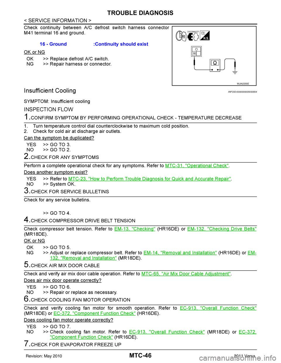
Check continuity between A/C defrost switch harness connector
M41 terminal 16 and ground.
OK or NG
OK >> Replace defrost A/C switch.
NG >> Repair harness or connector.
Insufficient CoolingINFOID:0000000005930854
SYMPTOM: Insufficient cooling
INSPECTION FLOW
1.CONFIRM SYMPTOM BY PERFORMING OPERATIONAL CHECK - TEMPERATURE DECREASE
1. Turn temperature control dial counterclockwise to maximum cold position.
2. Check for cold air at discharge air outlets.
Can the symptom be duplicated?
YES >> GO TO 3.
NO >> GO TO 2.
2.CHECK FOR ANY SYMPTOMS
Perform a complete operational check for any symptoms. Refer to MTC-31, "
Operational Check".
Does another symptom exist?
YES >> Refer to MTC-23, "How to Perform Trouble Diagnosis for Quick and Accurate Repair".
NO >> System OK.
3.CHECK FOR SERVICE BULLETINS
Check for any service bulletins.
>> GO TO 4.
4.CHECK COMPRESSOR DRIVE BELT TENSION
Check compressor belt tension. Refer to EM-13, "
Checking" (HR16DE) or EM-132, "Checking Drive Belts"
(MR18DE).
OK or NG
OK >> GO TO 5.
NG >> Adjust or replace compressor belt. Refer to EM-14, "
Removal and Installation" (HR16DE) or EM-
132, "Removal and Installation" (MR18DE).
5.CHECK AIR MIX DOOR CABLE
Check and verify air mix door cable operation. Refer to MTC-65, "
Air Mix Door Cable Adjustment".
Does air mix door operate correctly?
YES >> GO TO 6.
NO >> Repair or replace as necessary.
6.CHECK COOLING FAN MOTOR OPERATION
Check and verify cooling fan motor for smooth operation. Refer to EC-913, "
Overall Function Check"
(MR18DE) or EC-372, "Component Function Check" (HR16DE).
Does cooling fan motor operate correctly?
YES >> GO TO 7.
NO >> Check cooling fan motor. Refer to EC-913, "
Overall Function Check" (MR18DE) or EC-372,
"Component Function Check" (HR16DE).
7.CHECK FOR EVAPORATOR FREEZE UP16 - Ground :Continuity should exist
WJIA2255E
Revision: May 2010
2011 Versa