2011 NISSAN TIIDA Mechanical
[x] Cancel search: MechanicalPage 637 of 3787
INTELLIGENT KEY SYSTEMBL-127
< SERVICE INFORMATION >
C
DE
F
G H
J
K L
M A
B
BL
N
O P
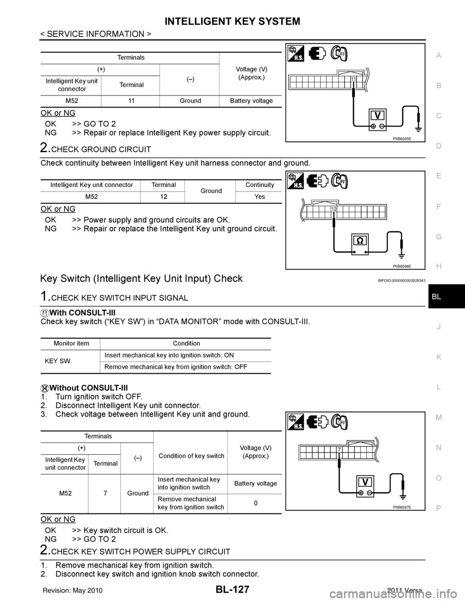
OK or NG
OK >> GO TO 2
NG >> Repair or replace Intelligent Key power supply circuit.
2.CHECK GROUND CIRCUIT
Check continuity between Intelligent Key unit harness connector and ground.
OK or NG
OK >> Power supply and ground circuits are OK.
NG >> Repair or replace the Intelligent Key unit ground circuit.
Key Switch (Intelligent Key Unit Input) CheckINFOID:0000000005929343
1.CHECK KEY SWITCH INPUT SIGNAL
With CONSULT-III
Check key switch (“KEY SW”) in “DATA MONITOR” mode with CONSULT-III.
Without CONSULT-III
1. Turn ignition switch OFF.
2. Disconnect Intelligent Key unit connector.
3. Check voltage between Intelligent Key unit and ground.
OK or NG
OK >> Key switch circuit is OK.
NG >> GO TO 2
2.CHECK KEY SWITCH POWER SUPPLY CIRCUIT
1. Remove mechanical key from ignition switch.
2. Disconnect key switch and i gnition knob switch connector.
Te r m i n a l s
Voltage (V)(Approx.)
(+)
(–)
Intelligent Key unit
connector Te r m i n a l
M52 11Ground Battery voltage
PIIB6595E
Intelligent Key unit connector Terminal
GroundContinuity
M52 12 Yes
PIIB6596E
Monitor item Condition
KEY SW Insert mechanical key into ignition switch: ON
Remove mechanical key from ignition switch: OFF
Te r m i n a l s
Condition of key switch Voltage (V)
(Approx.)
(+)
(–)
Intelligent Key
unit connector Te r m i n a l
M52 7 Ground Insert mechanical key
into ignition switch
Battery voltage
Remove mechanical
key from ignition switch 0
PIIB6597E
Revision: May 2010
2011 Versa
Page 638 of 3787
BL-128
< SERVICE INFORMATION >
INTELLIGENT KEY SYSTEM
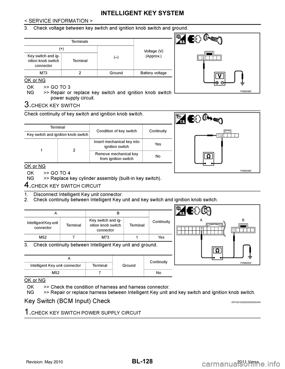
3. Check voltage between key switch and ignition knob switch and ground.
OK or NG
OK >> GO TO 3
NG >> Repair or replace key switch and ignition knob switchpower supply circuit.
3.CHECK KEY SWITCH
Check continuity of key switch and ignition knob switch.
OK or NG
OK >> GO TO 4
NG >> Replace key cylinder assembly (built-in key switch).
4.CHECK KEY SWITCH CIRCUIT
1. Disconnect Intelligent Key unit connector.
2. Check continuity between Intelligent Key unit and key switch and ignition knob switch.
3. Check continuity between Intelligent Key unit and ground.
OK or NG
OK >> Check the condition of harness and harness connector.
NG >> Repair or replace harness between Intelligent Key unit and key switch and ignition knob switch.
Key Switch (BCM Input) CheckINFOID:0000000005929344
1.CHECK KEY SWITCH PO WER SUPPLY CIRCUIT
Te r m i n a l s
Voltage (V)(Approx.)
(+)
(–)
Key switch and ig-
nition knob switch
connector Te r m i n a l
M73 2Ground Battery voltage
PIIB6598E
Te r m i n a l
Condition of key switch Continuity
Key switch and ignition knob switch
12 Insert mechanical key into
ignition switch Ye s
Remove mechanical key from ignition switch No
PIIB6599E
AB
Continuity
Intelligent Key unit
connector Te r m i n a lKey switch and ig-
nition knob switch connector Te r m i n a l
M52 7M73 1Yes
A GroundContinuity
Intelligent Key unit connector Terminal
M52 7 No
PIIB6600E
Revision: May 2010 2011 Versa
Page 639 of 3787
INTELLIGENT KEY SYSTEMBL-129
< SERVICE INFORMATION >
C
DE
F
G H
J
K L
M A
B
BL
N
O P
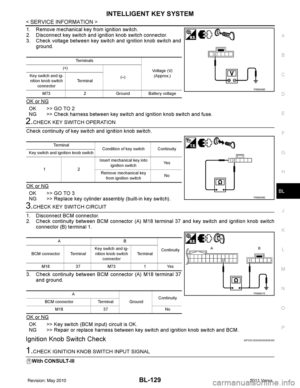
1. Remove mechanical key from ignition switch.
2. Disconnect key switch and i gnition knob switch connector.
3. Check voltage between key switch and ignition knob switch and
ground.
OK or NG
OK >> GO TO 2
NG >> Check harness between key switch and ignition knob switch and fuse.
2.CHECK KEY SWITCH OPERATION
Check continuity of key switch and ignition knob switch.
OK or NG
OK >> GO TO 3
NG >> Replace key cylinder assembly (built-in key switch).
3.CHECK KEY SWITCH CIRCUIT
1. Disconnect BCM connector.
2. Check continuity between BCM connector (A) M18 terminal 37 and key switch and ignition knob switch
connector (B) terminal 1.
3. Check continuity between BCM connector (A) M18 terminal 37 and ground.
OK or NG
OK >> Key switch (BCM input) circuit is OK.
NG >> Repair or replace harness between key switch and ignition knob switch and BCM.
Ignition Knob Switch CheckINFOID:0000000005929345
1.CHECK IGNITION KNOB SWITCH INPUT SIGNAL
With CONSULT-III
Te r m i n a l s
Voltage (V)(Approx.)
(+)
(–)
Key switch and ig-
nition knob switch
connector Te r m i n a l
M73 2Ground Battery voltage
PIIB6598E
Te r m i n a l
Condition of key switch Continuity
Key switch and ignition knob switch
12 Insert mechanical key into
ignition switch Ye s
Remove mechanical key from ignition switch No
PIIB6599E
AB
Continuity
BCM connector Terminal Key switch and ig-
nition knob switch connector Te r m i n a l
M18 37M73 1Yes
A GroundContinuity
BCM connector Terminal
M18 37 No
PIIB6601E
Revision: May 2010 2011 Versa
Page 690 of 3787

BL-180
< SERVICE INFORMATION >
BACK DOOR LOCK
1: With Intelligent Key
2: Without Intelligent Key
3: Hatchback without Intelligent Key
4: Sedan without Intelligent Key
5: Hatchback
6: Sedan
7: With power door locks
8: With power windows
Terminal and Reference Value for Intelligent Key UnitINFOID:0000000006215775
63 BR Interior room lamp Output OFFAny door
switchON (open)
0V
OFF (closed) Battery voltage
65
7SB All door lock actuators
(lock) Output OFFOFF (neutral)
0V
ON (lock) Battery voltage
66
7G Front door lock actua-
tor RH, rear door lock
actuators LH/RH (un-
lock) Output OFFOFF (neutral)
0V
ON (unlock) Battery voltage
67 B Ground Input ON—0V
68
8L Power window power
supply (RAP)
Output —Ignition switch ON
Battery voltage
Within 45 seconds after igni-
tion switch OFF Battery voltage
More than 45 seconds after ig-
nition switch OFF 0V
When front door LH or RH is
open or power window timer
operates 0V
69
8P Battery power supply OutputOFF
— Battery voltage
70 Y Battery power supply Input OFF —Battery voltage
Te r m i n a l
Wire
color Signal name Signal
input/
output Measuring condition
Reference value or waveform
(Approx.)
Ignition
switch Operation or condition
Te r m i n a lWire
Color Item Condition
Voltage (V)Approx.
Ignition
Switch
Position Operation or Conditions
1R Steering lock solenoid
power supply
LOCK
— 5
2 L CAN-H —— —
3 P CAN-L —— —
4O Intelligent Key warning
buzzer LOCKOperate door request
switch. Buzzer OFF
Battery voltage
Sound buzzer 0
5G Front door request
switch LH —Press door request switch (driver side).
0
Other than above 5
6 Y Ignition switch (ON) ON —Battery voltage
7 LG Key switch LOCKInsert mechanical key into ignition switch. Battery voltage
Remove mechanical key from ignition
switch.
0
Revision: May 2010
2011 Versa
Page 691 of 3787
BACK DOOR LOCKBL-181
< SERVICE INFORMATION >
C
DE
F
G H
J
K L
M A
B
BL
N
O P
10*1W CVT or A/T shift selec-
tor (park position
switch)
ONShift lever in park position.
0
Other than above Battery voltage
11 SB Power source (Fus e) — —Battery voltage
12 B Ground —— 0
13 V Instrument panel an-
tenna (+) signal
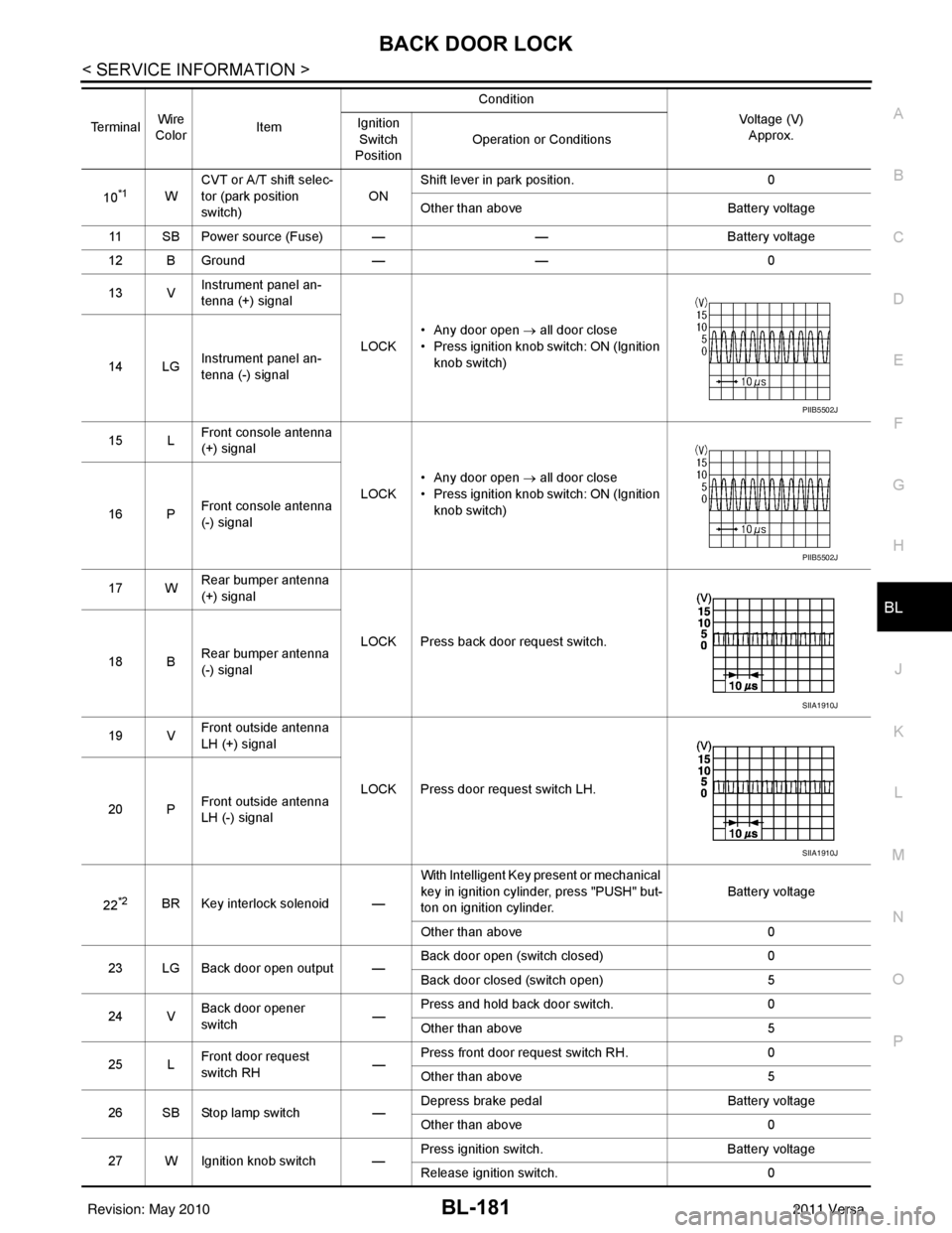
LOCK• Any door open
→ all door close
• Press ignition knob switch: ON (Ignition knob switch)
14 LG Instrument panel an-
tenna (-) signal
15 L Front console antenna
(+) signal
LOCK• Any door open
→ all door close
• Press ignition knob switch: ON (Ignition knob switch)
16 P Front console antenna
(-) signal
17 W Rear bumper antenna
(+) signal
LOCK Press back door request switch.
18 B Rear bumper antenna
(-) signal
19 V Front outside antenna
LH (+) signal
LOCK Press door request switch LH.
20 P Front outside antenna
LH (-) signal
22
*2BR Key interlock solenoid — With Intelligent Key present or mechanical
key in ignition cylinder, press "PUSH" but-
ton on ignition cylinder.
Battery voltage
Other than above 0
23 LG Back door open output — Back door open (switch closed)
0
Back door closed (switch open) 5
24 V Back door opener
switch —Press and hold back door switch.
0
Other than above 5
25 L Front door request
switch RH
—Press front door request switch RH.
0
Other than above 5
26 SB Stop lamp switch —Depress brake pedal
Battery voltage
Other than above 0
27 W Ignition knob switch — Press ignition switch.
Battery voltage
Release ignition switch. 0
Terminal
Wire
Color Item Condition
Voltage (V)Approx.
Ignition
Switch
Position Operation or Conditions
PIIB5502J
PIIB5502J
SIIA1910J
SIIA1910J
Revision: May 2010
2011 Versa
Page 715 of 3787

TRUNK LID OPENERBL-205
< SERVICE INFORMATION >
C
DE
F
G H
J
K L
M A
B
BL
N
O P
1: With Intelligent Key
2: Without Intelligent Key
3: Hatchback without Intelligent Key
4: Sedan without Intelligent Key
5: Hatchback
6: Sedan
7: With power door locks
8: With power windows
Terminal and Reference Valu e for Intelligent Key UnitINFOID:0000000006215778
63 BR Interior room lamp Output OFF Any door
switchON (open)
0V
OFF (closed) Battery voltage
65
7SB All door lock actuators
(lock) Output OFFOFF (neutral)
0V
ON (lock) Battery voltage
66
7G Front door lock actua-
tor RH, rear door lock
actuators LH/RH (un-
lock) Output OFFOFF (neutral)
0V
ON (unlock) Battery voltage
67 B Ground Input ON—0V
68
8L Power window power
supply (RAP)
Output —Ignition switch ON
Battery voltage
Within 45 seconds after igni-
tion switch OFF Battery voltage
More than 45 seconds after ig-
nition switch OFF 0V
When front door LH or RH is
open or power window timer
operates 0V
69
8P Battery power supply OutputOFF
— Battery voltage
70 Y Battery power supply Input OFF —Battery voltage
Te r m i n a l
Wire
color Signal name Signal
input/
output Measuring condition
Reference value or waveform
(Approx.)
Ignition
switch Operation or condition
TerminalWire
Color Item Condition
Voltage (V)Approx.
Ignition
Switch
Position Operation or Conditions
1R Steering lock solenoid
power supply
LOCK
— 5
2 L CAN-H —— —
3 P CAN-L —— —
4O Intelligent Key warning
buzzer LOCKOperate door request
switch. Buzzer OFF
Battery voltage
Sound buzzer 0
5G Front door request
switch LH —Press door request switch (driver side).
0
Other than above 5
6 Y Ignition switch (ON) ON —Battery voltage
7 LG Key switch LOCKInsert mechanical key into ignition switch. Battery voltage
Remove mechanical key from ignition
switch.
0
Revision: May 2010
2011 Versa
Page 716 of 3787
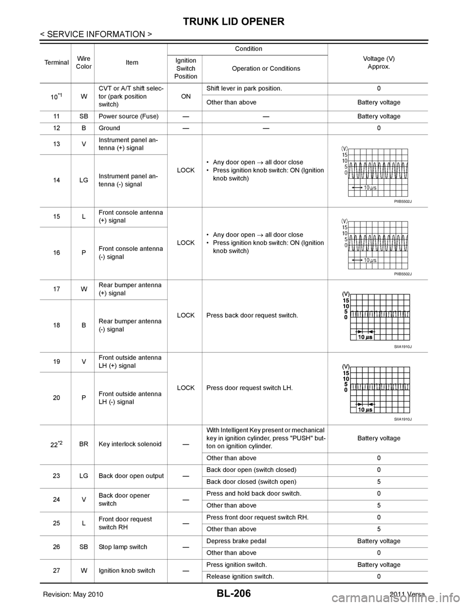
BL-206
< SERVICE INFORMATION >
TRUNK LID OPENER
10*1WCVT or A/T shift selec-
tor (park position
switch)
ONShift lever in park position.
0
Other than above Battery voltage
11 SB Power source (Fuse) — —Battery voltage
12 B Ground —— 0
13 V Instrument panel an-
tenna (+) signal
LOCK• Any door open
→ all door close
• Press ignition knob switch: ON (Ignition knob switch)
14 LG Instrument panel an-
tenna (-) signal
15 L Front console antenna
(+) signal
LOCK• Any door open
→ all door close
• Press ignition knob switch: ON (Ignition knob switch)
16 P Front console antenna
(-) signal
17 W Rear bumper antenna
(+) signal
LOCK Press back door request switch.
18 B Rear bumper antenna
(-) signal
19 V Front outside antenna
LH (+) signal
LOCK Press door request switch LH.
20 P Front outside antenna
LH (-) signal
22
*2BR Key interlock solenoid — With Intelligent Key present or mechanical
key in ignition cylinder, press "PUSH" but-
ton on ignition cylinder.
Battery voltage
Other than above 0
23 LG Back door open output — Back door open (switch closed)
0
Back door closed (switch open) 5
24 V Back door opener
switch —Press and hold back door switch.
0
Other than above 5
25 L Front door request
switch RH
—Press front door request switch RH.
0
Other than above 5
26 SB Stop lamp switch —Depress brake pedal
Battery voltage
Other than above 0
27 W Ignition knob switch — Press ignition switch.
Battery voltage
Release ignition switch. 0
Te r m i n a l
Wire
Color Item Condition
Voltage (V)Approx.
Ignition
Switch
Position Operation or Conditions
PIIB5502J
PIIB5502J
SIIA1910J
SIIA1910J
Revision: May 2010
2011 Versa
Page 740 of 3787

BL-230
< SERVICE INFORMATION >
VEHICLE SECURITY (THEFT WARNING) SYSTEM
1: With Intelligent Key
2: Without Intelligent Key
3: Hatchback without Intelligent Key
4: Sedan without Intelligent Key
5: Hatchback
6: Sedan
7: With power door locks
8: With power windows
Terminal and Reference Value for Intelligent Key UnitINFOID:0000000006215780
63 BR Interior room lamp Output OFF Any door
switchON (open)
0V
OFF (closed) Battery voltage
65
7SB All door lock actuators
(lock) Output OFFOFF (neutral)
0V
ON (lock) Battery voltage
66
7G Front door lock actua-
tor RH, rear door lock
actuators LH/RH (un-
lock) Output OFFOFF (neutral)
0V
ON (unlock) Battery voltage
67 B Ground Input ON—0V
68
8L Power window power
supply (RAP)
Output —Ignition switch ON
Battery voltage
Within 45 seconds after igni-
tion switch OFF Battery voltage
More than 45 seconds after ig-
nition switch OFF 0V
When front door LH or RH is
open or power window timer
operates 0V
69
8P Battery power supply OutputOFF
— Battery voltage
70 Y Battery power supply Input OFF —Battery voltage
Te r m i n a l
Wire
color Signal name Signal
input/
output Measuring condition
Reference value or waveform
(Approx.)
Ignition
switch Operation or condition
Te r m i n a lWire
Color Item Condition
Voltage (V)Approx.
Ignition
Switch
Position Operation or Conditions
1R Steering lock solenoid
power supply
LOCK
— 5
2 L CAN-H —— —
3 P CAN-L —— —
4O Intelligent Key warning
buzzer LOCKOperate door request
switch. Buzzer OFF
Battery voltage
Sound buzzer 0
5G Front door request
switch LH —Press door request switch (driver side).
0
Other than above 5
6 Y Ignition switch (ON) ON —Battery voltage
7 LG Key switch LOCKInsert mechanical key into ignition switch. Battery voltage
Remove mechanical key from ignition
switch.
0
Revision: May 2010
2011 Versa