2011 NISSAN TIIDA wheel bolts
[x] Cancel search: wheel boltsPage 2697 of 3787
FSU-12
< SERVICE INFORMATION >
COIL SPRING AND STRUT
COIL SPRING AND STRUT
Removal and InstallationINFOID:0000000005930902
REMOVAL
1. Remove cowl top panel. Refer to EI-24, "Removal and Installation".
2. Remove front tires using power tool.
3. Remove harness of wheel sensor from strut assembly. Refer to BRC-33, "
Removal and Installation".
CAUTION:
Do not pull on wheel sensor harness.
4. Remove brake hose lock plate. Refer to BR-12, "
Rear Brake Tube and Hose".
5. Remove the nut on the upper side of stabilizer connecting rod using power tool, and then remove stabi- lizer connecting rod from strut assembly.
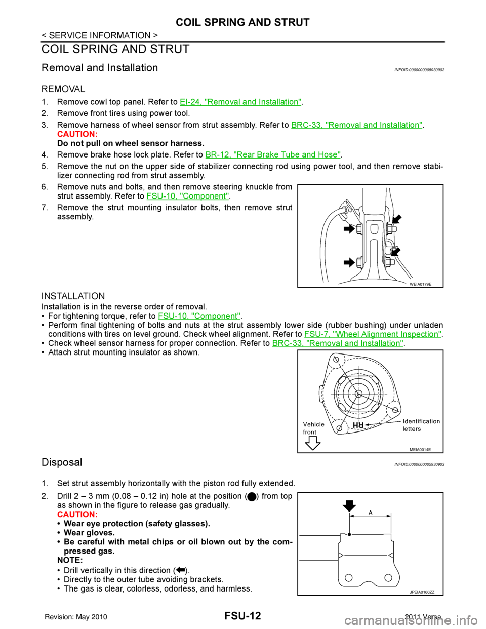
6. Remove nuts and bolts, and then remove steering knuckle from strut assembly. Refer to FSU-10, "
Component".
7. Remove the strut mounting insulator bolts, then remove strut assembly.
INSTALLATION
Installation is in the reverse order of removal.
• For tightening torque, refer to FSU-10, "
Component".
• Perform final tightening of bolts and nuts at the strut assembly lower side (rubber bushing) under unladen
conditions with tires on level ground. Check wheel alignment. Refer to FSU-7, "
Wheel Alignment Inspection".
• Check wheel sensor harness for proper connection. Refer to BRC-33, "
Removal and Installation".
• Attach strut mounting insulator as shown.
DisposalINFOID:0000000005930903
1. Set strut assembly horizontally with the piston rod fully extended.
2. Drill 2 – 3 mm (0.08 – 0.12 in) hole at the position ( ) from top
as shown in the figure to release gas gradually.
CAUTION:
• Wear eye protection (safety glasses).
• Wear gloves.
• Be careful with metal chips or oil blown out by the com-pressed gas.
NOTE:
• Drill vertically in this direction ( ).
• Directly to the outer tube avoiding brackets.
• The gas is clear, colorless, odorless, and harmless.
WEIA0179E
MEIA0014E
JPEIA0160ZZ
Revision: May 2010 2011 Versa
Page 2700 of 3787
TRANSVERSE LINKFSU-15
< SERVICE INFORMATION >
C
DF
G H
I
J
K L
M A
B
FSU
N
O P
TRANSVERSE LINK
Removal and InstallationINFOID:0000000006414956
REMOVAL
1. Remove wheel and tire. Refer to WT-7, "Adjustment".
2. Remove transverse link ball joint nut and bolt. Then, remove transverse link from steering knuckle.
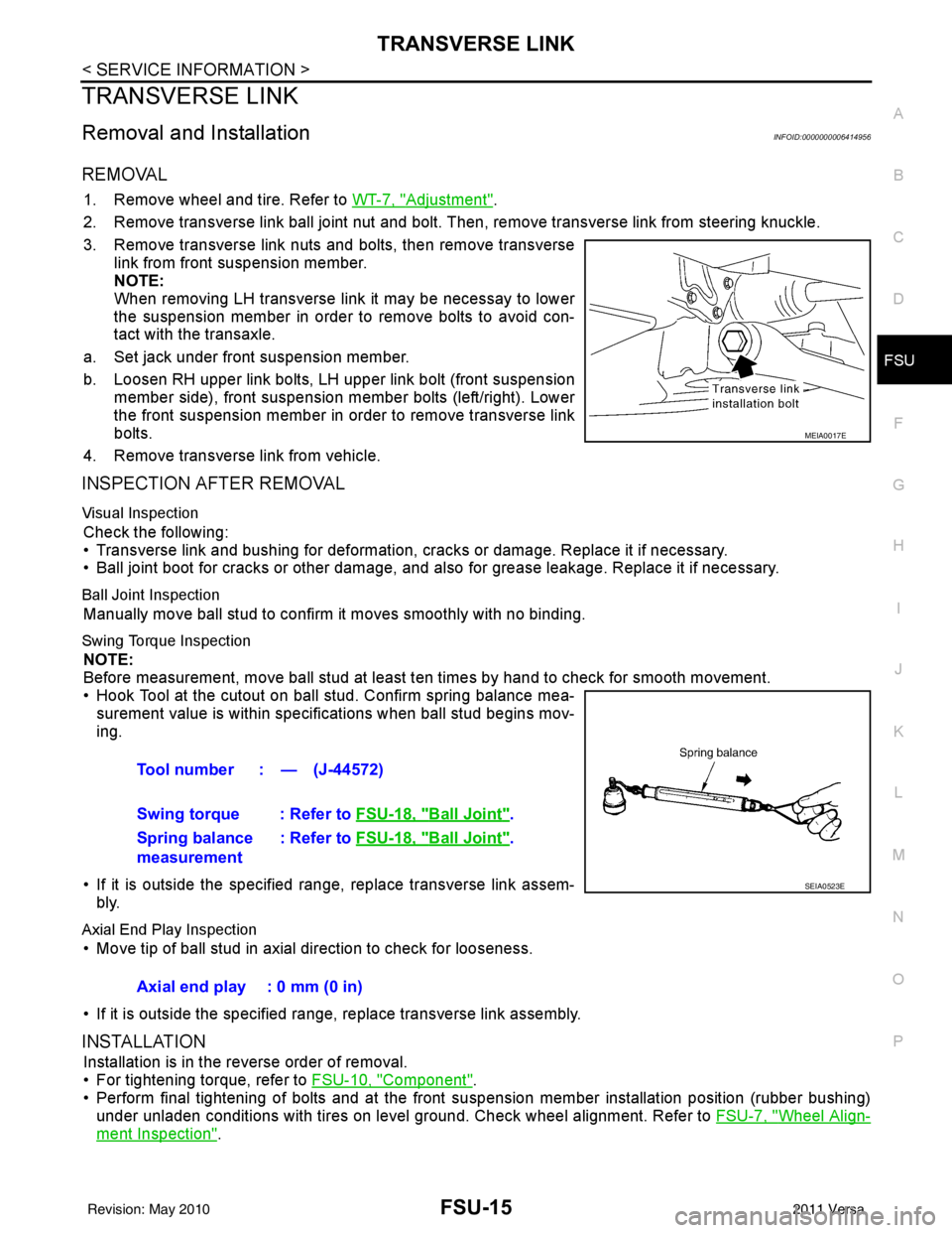
3. Remove transverse link nuts and bolts, then remove transverse link from front suspension member.
NOTE:
When removing LH transverse link it may be necessay to lower
the suspension member in order to remove bolts to avoid con-
tact with the transaxle.
a. Set jack under front suspension member.
b. Loosen RH upper link bolts, LH upper link bolt (front suspension member side), front suspension member bolts (left/right). Lower
the front suspension member in order to remove transverse link
bolts.
4. Remove transverse link from vehicle.
INSPECTION AFTER REMOVAL
Visual Inspection
Check the following:
• Transverse link and bushing for deformation, cracks or damage. Replace it if necessary.
• Ball joint boot for cracks or other damage, and also for grease leakage. Replace it if necessary.
Ball Joint Inspection
Manually move ball stud to confirm it moves smoothly with no binding.
Swing Torque Inspection
NOTE:
Before measurement, move ball stud at least ten times by hand to check for smooth movement.
• Hook Tool at the cutout on ball stud. Confirm spring balance mea- surement value is within specifications when ball stud begins mov-
ing.
• If it is outside the specified range, replace transverse link assem- bly.
Axial End Play Inspection
• Move tip of ball stud in axial direction to check for looseness.
• If it is outside the specified range, replace transverse link assembly.
INSTALLATION
Installation is in the reverse order of removal.
• For tightening torque, refer to FSU-10, "
Component".
• Perform final tightening of bolts and at the front suspension member installation position (rubber bushing)
under unladen conditions with tires on level ground. Check wheel alignment. Refer to FSU-7, "
Wheel Align-
ment Inspection".
MEIA0017E
Tool number : — (J-44572)
Swing torque : Refer to FSU-18, "
Ball Joint".
Spring balance
measurement : Refer to
FSU-18, "
Ball Joint".
SEIA0523E
Axial end play : 0 mm (0 in)
Revision: May 2010 2011 Versa
Page 2705 of 3787

GI-1
GENERAL INFORMATION
C
DE
F
G H
I
J
K L
M B
GI
SECTION GI
N
O P
CONTENTS
GENERAL INFORMATION
SERVICE INFORMATION .. ..........................2
PRECAUTIONS .............................................. .....2
Description .......................................................... ......2
Precaution for Supplemental Restraint System
(SRS) "AIR BAG" and "SEAT BELT PRE-TEN-
SIONER" ...................................................................
2
Precaution Necessary for Steering Wheel Rota-
tion After Battery Disconnect ............................... ......
2
General Precaution ...................................................3
Precaution for Three Way Catalyst ...........................4
Precaution for Fuel (Unleaded Regular Gasoline
Recommended) .........................................................
4
Precaution for Multiport Fuel Injection System or
Engine Control System .............................................
5
Precaution for Hoses .................................................5
Precaution for Engine Oils ........................................6
Precaution for Air Conditioning .................................6
HOW TO USE THIS MANUAL ............................7
Description .......................................................... ......7
Terms ........................................................................7
Units ..........................................................................7
Contents ....................................................................7
Relation between Illustrations and Descriptions .......8
Component ................................................................8
How to Follow Trouble Diagnosis ..............................9
How to Read Wiring Diagram ..................................13
Abbreviations ...................................................... ....20
SERVICE INFORMATION FOR ELECTRICAL
INCIDENT ...........................................................
22
How to Check Terminal ...........................................22
How to Perform Efficient Diagnosis for an Electri-
cal Incident .......................................................... ....
25
Control Units and Electrical Parts ............................32
CONSULT-III CHECKING SYSTEM .................35
Description ...............................................................35
Function and System Application ............................35
CONSULT-III Data Link Connector (DLC) Circuit ....36
LIFTING POINT .................................................38
Special Service Tool ................................................38
Garage Jack and Safety Stand and 2-Pole Lift .......38
Board-On Lift ...........................................................39
TOW TRUCK TOWING .....................................40
Tow Truck Towing ...................................................40
Vehicle Recovery (Freeing a Stuck Vehicle) ...........40
TIGHTENING TORQUE OF STANDARD
BOLTS ...............................................................
41
Tightening Torque Table .........................................41
RECOMMENDED CHEMICAL PRODUCTS
AND SEALANTS ...............................................
42
Recommended Chemical Product and Sealant .......42
IDENTIFICATION INFORMATION ....................43
Model Variation ........................................................43
Dimensions ..............................................................46
Wheels & Tires ........................................................46
TERMINOLOGY ................................................47
SAE J1930 Terminology List ...................................47
Revision: May 2010 2011 Versa
Page 3218 of 3787
CHASSIS AND BODY MAINTENANCEMA-47
< SERVICE INFORMATION >
C
DE
F
G H
I
J
K
M A
B
MA
N
O P
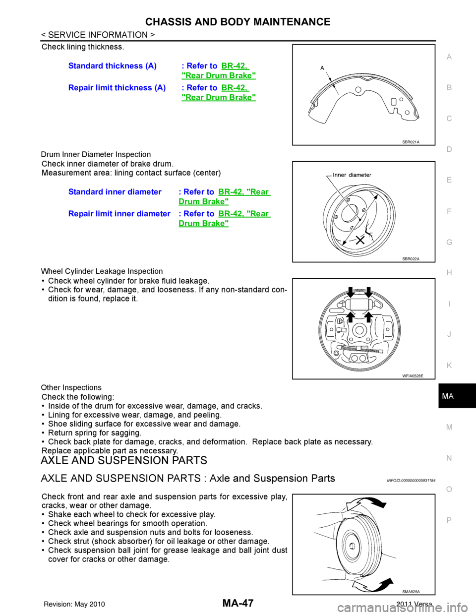
Check lining thickness.
Drum Inner Diameter Inspection
Check inner diameter of brake drum.
Measurement area: lining contact surface (center)
Wheel Cylinder Leakage Inspection
• Check wheel cylinder for brake fluid leakage.
• Check for wear, damage, and looseness. If any non-standard con- dition is found, replace it.
Other Inspections
Check the following:
• Inside of the drum for excessive wear, damage, and cracks.
• Lining for excessive wear, damage, and peeling.
• Shoe sliding surface for excessive wear and damage.
• Return spring for sagging.
• Check back plate for damage, cracks, and deformation. Replace back plate as necessary.
Replace applicable part as necessary.
AXLE AND SUSPENSION PARTS
AXLE AND SUSPENSION PARTS : Axle and Suspension PartsINFOID:0000000005931184
Check front and rear axle and suspension parts for excessive play,
cracks, wear or other damage.
• Shake each wheel to check for excessive play.
• Check wheel bearings for smooth operation.
• Check axle and suspension nuts and bolts for looseness.
• Check strut (shock absorber) for oil leakage or other damage.
• Check suspension ball joint for grease leakage and ball joint dust
cover for cracks or other damage. Standard thickness (A) : Refer to
BR-42,
"Rear Drum Brake"
Repair limit thickness (A) : Refer toBR-42,
"Rear Drum Brake"
SBR021A
Standard inner diameter : Refer toBR-42, "Rear
Drum Brake"
Repair limit inner diameter : Refer toBR-42, "Rear
Drum Brake"
SBR022A
WFIA0528E
SMA525A
Revision: May 2010 2011 Versa
Page 3498 of 3787
PS-4
< SERVICE INFORMATION >
PREPARATION
PREPARATION
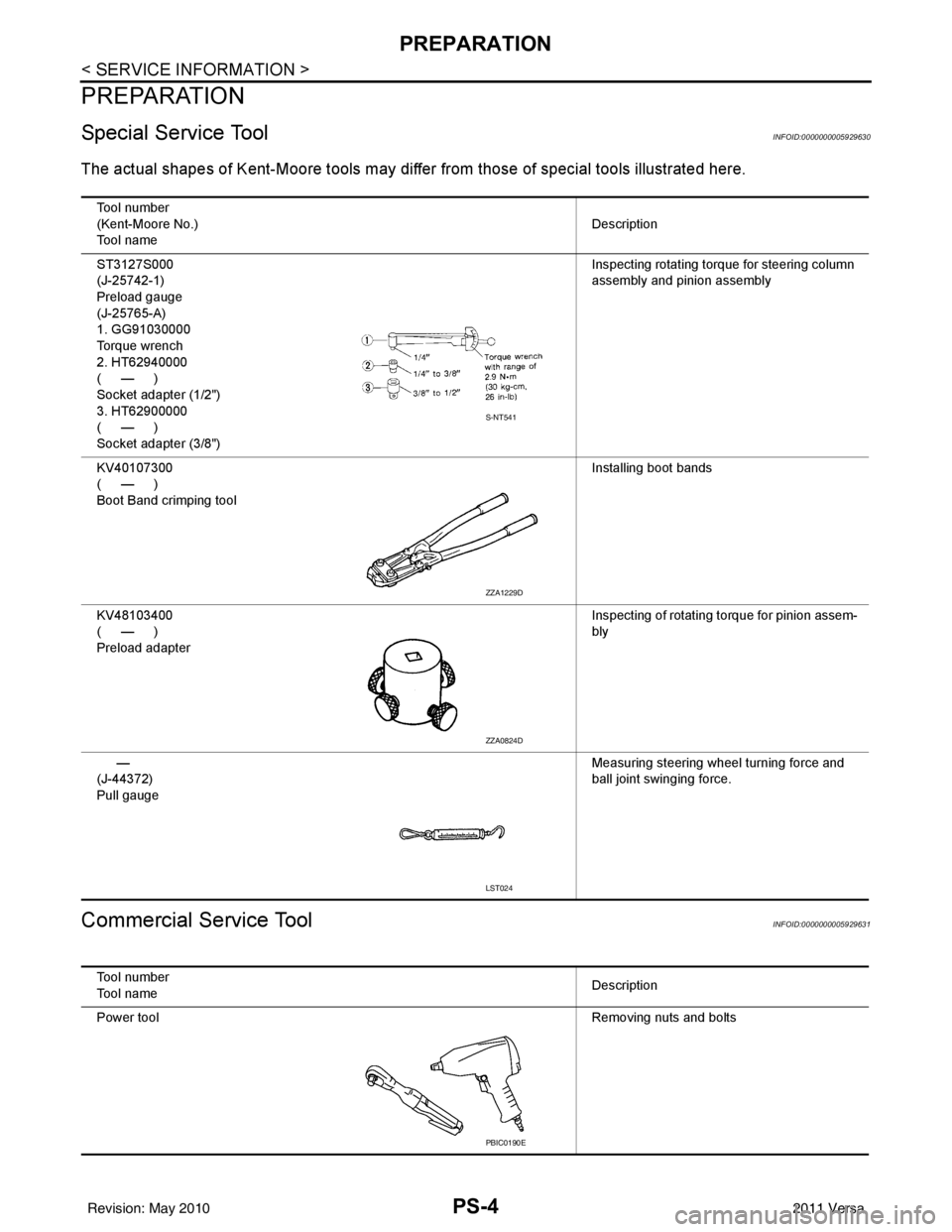
Special Service ToolINFOID:0000000005929630
The actual shapes of Kent-Moore tools may differ from thos e of special tools illustrated here.
Commercial Service ToolINFOID:0000000005929631
Tool number
(Kent-Moore No.)
Tool name Description
ST3127S000
(J-25742-1)
Preload gauge
(J-25765-A)
1. GG91030000
Torque wrench
2. HT62940000
(—)
Socket adapter (1/2")
3. HT62900000
(—)
Socket adapter (3/8") Inspecting rotating torque for steering column
assembly and pinion assembly
KV40107300
(—)
Boot Band crimping tool Installing boot bands
KV48103400
(—)
Preload adapter Inspecting of rotating torque for pinion assem-
bly
—
(J-44372)
Pull gauge Measuring steering wheel turning force and
ball joint swinging force.
S-NT541
ZZA1229D
ZZA0824D
LST024
Tool number
Tool name
Description
Power tool Removing nuts and bolts
PBIC0190E
Revision: May 2010 2011 Versa
Page 3500 of 3787
PS-6
< SERVICE INFORMATION >
STEERING WHEEL
STEERING WHEEL
On-Vehicle Inspection and ServiceINFOID:0000000006416714
CHECKING CONDITION OF INSTALLATION
• Check installation conditions of steering gear assembly, front suspension assembly, axle and steering col-
umn assembly.
• Check if movement exists when steering wheel is mo ved up and down, to the left and right and to the axial
direction.
• Check steering gear assembly bolts and nuts for looseness. Refer to PS-15, "
Removal and Installation".
CHECKING STEERING WHEEL PLAY
• Turn steering wheel so that front wheels come to the straight-ahead position. Start engine and lightly turn
steering wheel to the left and right until front wheels start to move. Measure steering wheel movement on the
outer circumference.
• When the measurement value is outside the standard val ue, check backlash for each joint of steering col-
umn assembly and installation condition of steering gear assembly.
CHECKING NEUTRAL POSITION STEERING WHEEL
• Make sure that steering gear assembly, steering column assembly and steering wheel are installed in the correct position.
• Perform neutral position inspection after wheel alignment. Refer to PS-2, "
Precaution for Supplemental
Restraint System (SRS) "AIR BAG" and "SEAT BELT PRE-TENSIONER"".
• Set vehicle to the straight-ahead position and c onfirm steering wheel is in the neutral position.
• Loosen outer socket lock nut and turn inner socket to left and right equally to make fine adjustments if steer-
ing wheel is not in the neutral position.
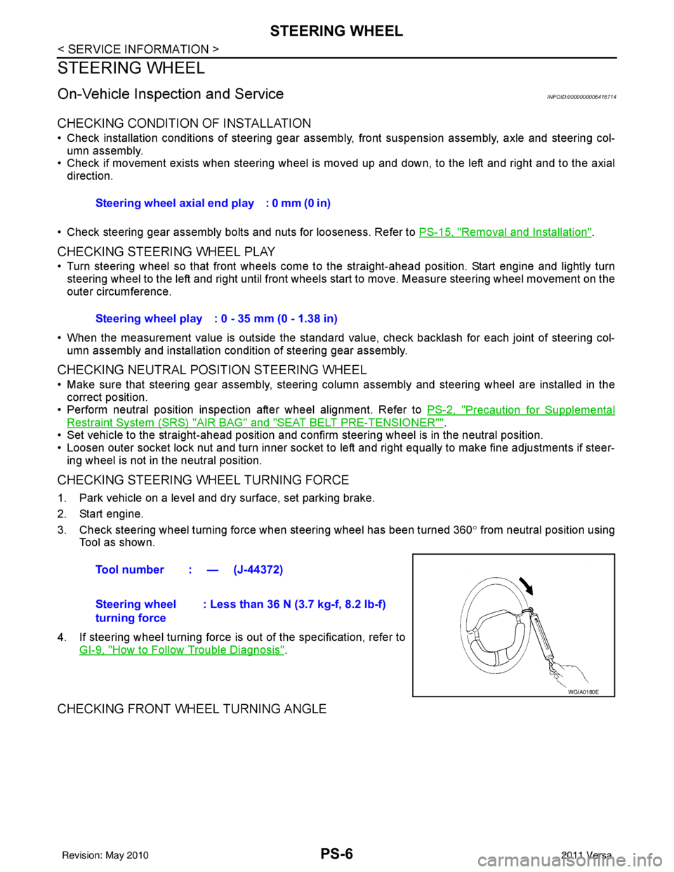
CHECKING STEERING WHEEL TURNING FORCE
1. Park vehicle on a level and dry surface, set parking brake.
2. Start engine.
3. Check steering wheel turning force when steering wheel has been turned 360 ° from neutral position using
Tool as shown.
4. If steering wheel turning force is out of the specification, refer to GI-9, "
How to Follow Trouble Diagnosis".
CHECKING FRONT WHEEL TURNING ANGLE
Steering wheel axial end play : 0 mm (0 in)
Steering wheel play : 0 - 35 mm (0 - 1.38 in)
Tool number : — (J-44372)
Steering wheel
turning force : Less than 36 N (3.7 kg-f, 8.2 lb-f)
WGIA0180E
Revision: May 2010
2011 Versa
Page 3509 of 3787
POWER STEERING GEARPS-15
< SERVICE INFORMATION >
C
DE
F
H I
J
K L
M A
B
PS
N
O P
POWER STEERING GEAR
Removal and InstallationINFOID:0000000005929636
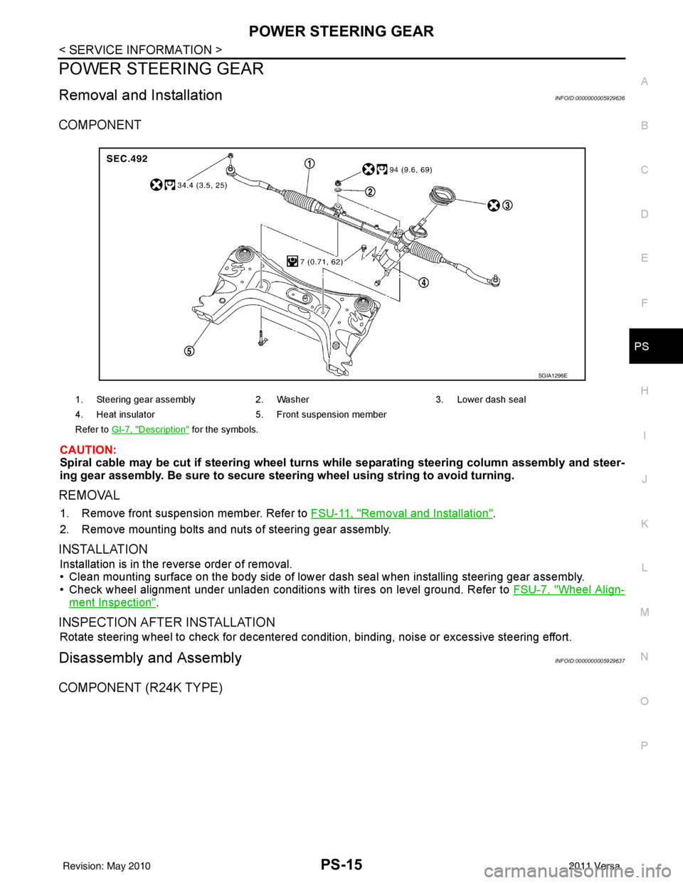
COMPONENT
CAUTION:
Spiral cable may be cut if steering wheel turns while separating steering column assembly and steer-
ing gear assembly. Be sure to secure steering wheel using stri ng to avoid turning.
REMOVAL
1. Remove front suspension member. Refer to FSU-11, "Removal and Installation".
2. Remove mounting bolts and nuts of steering gear assembly.
INSTALLATION
Installation is in the reverse order of removal.
• Clean mounting surface on the body side of lower dash seal when installing steering gear assembly.
• Check wheel alignment under unladen conditions with tires on level ground. Refer to FSU-7, "
Wheel Align-
ment Inspection".
INSPECTION AFTER INSTALLATION
Rotate steering wheel to check for decentered condition, binding, noise or excessive steering effort.
Disassembly and AssemblyINFOID:0000000005929637
COMPONENT (R24K TYPE)
1. Steering gear assembly2. Washer 3. Lower dash seal
4. Heat insulator 5. Front suspension member
Refer to GI-7, "
Description" for the symbols.
SGIA1296E
Revision: May 2010 2011 Versa
Page 3522 of 3787
WHEEL HUBRAX-7
< SERVICE INFORMATION >
CEF
G H
I
J
K L
M A
B
RAX
N
O P
Do not pull on wheel sensor harness.
3. Remove the brake drum only. Refer to BR-36, "
Removal and Installation of Drum Brake Assembly".
4. Remove wheel hub and bearing assembly bolts, and then remove wheel hub and bearing assembly from vehicle.
5. Suspend back plate with suitable wire, or if necessary, remove back plate using the following procedure. 1. Remove parking brake rear cable from back plate. Refer to PB-6, "
Removal and Installation".
2. Separate brake tube from wheel cylinder. Refer to BR-12, "
Rear Brake Tube and Hose".
INSPECTION AFTER REMOVAL
Check for any deformity, cracks, or other damage on the wheel hub assembly, replace if necessary.
CAUTION:
The wheel hub assembly does not requ ire maintenance. If any of the following symptoms are noted,
replace the wheel hub assembly.
• Growling noise is emitted from the wheel hub bearing during operation.
• Wheel hub bearing drags or turns roughly.
INSTALLATION
Installation is in the reverse order of removal.
Revision: May 2010 2011 Versa