2011 NISSAN TIIDA parts
[x] Cancel search: partsPage 114 of 3787
P0710 TRANSMISSION FLUID TEMPERATURE SENSOR AAT-97
< SERVICE INFORMATION >
DE
F
G H
I
J
K L
M A
B
AT
N
O P
With CONSULT-III
1. Start engine.
2. Select “TCM INPUT SIGNALS” in “DATA MONI TOR” mode for “TRANSMISSION” with CONSULT-III.
3. Read out the value of “FLUID TEMP SE”.
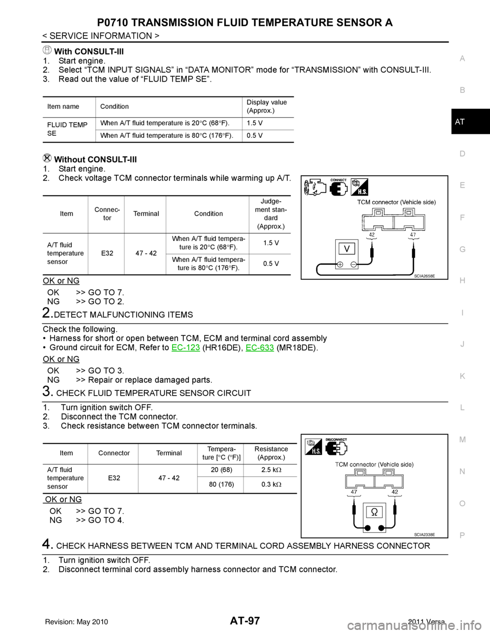
Without CONSULT-III
1. Start engine.
2. Check voltage TCM connector terminals while warming up A/T.
OK or NG
OK >> GO TO 7.
NG >> GO TO 2.
2.DETECT MALFUNCTIONING ITEMS
Check the following.
• Harness for short or open between TCM, ECM and terminal cord assembly
• Ground circuit for ECM, Refer to EC-123
(HR16DE), EC-633 (MR18DE).
OK or NG
OK >> GO TO 3.
NG >> Repair or replace damaged parts.
3. CHECK FLUID TEMPERATURE SENSOR CIRCUIT
1. Turn ignition switch OFF.
2. Disconnect the TCM connector.
3. Check resistance between TCM connector terminals.
OK or NG
OK >> GO TO 7.
NG >> GO TO 4.
4. CHECK HARNESS BETWEEN TCM AND TERMINAL CORD ASSEMBLY HARNESS CONNECTOR
1. Turn ignition switch OFF.
2. Disconnect terminal cord assemb ly harness connector and TCM connector.
Item name Condition Display value
(Approx.)
FLUID TEMP
SE When A/T fluid temperature is 20
°C (68 °F). 1.5 V
When A/T fluid temperature is 80 °C (176 °F). 0.5 V
Item Connec-
tor Terminal
Condition Judge-
ment stan- dard
(Approx.)
A/T fluid
temperature
sensor E32 47 - 42 When A/T fluid tempera-
ture is 20 °C (68 °F). 1.5 V
When A/T fluid tempera- ture is 80 °C (176 °F). 0.5 V
SCIA2658E
Item Connector Terminal Te m p e r a -
ture [ °C ( °F)] Resistance
(Approx.)
A/T fluid
temperature
sensor E32
47 - 42 20 (68) 2.5 k
Ω
80 (176) 0.3 k Ω
SCIA2338E
Revision: May 2010 2011 Versa
Page 115 of 3787
AT-98
< SERVICE INFORMATION >
P0710 TRANSMISSION FLUID TEMPERATURE SENSOR A
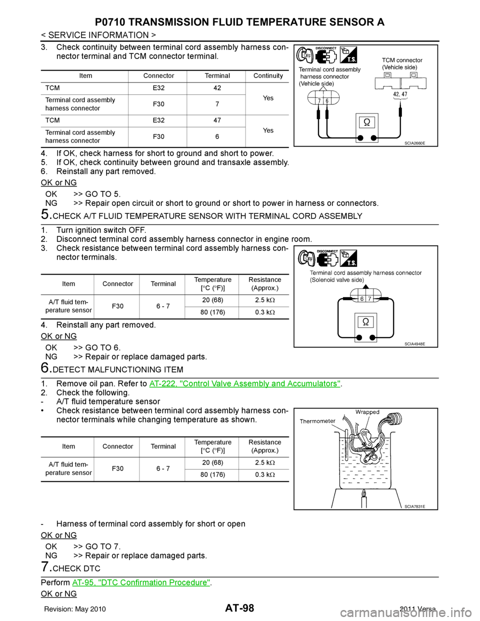
3. Check continuity between terminal cord assembly harness con-
nector terminal and TCM connector terminal.
4. If OK, check harness for short to ground and short to power.
5. If OK, check continuity bet ween ground and transaxle assembly.
6. Reinstall any part removed.
OK or NG
OK >> GO TO 5.
NG >> Repair open circuit or short to ground or short to power in harness or connectors.
5.CHECK A/T FLUID TEMPERATURE SENSO R WITH TERMINAL CORD ASSEMBLY
1. Turn ignition switch OFF.
2. Disconnect terminal cord assembly harness connector in engine room.
3. Check resistance between terminal cord assembly harness con- nector terminals.
4. Reinstall any part removed.
OK or NG
OK >> GO TO 6.
NG >> Repair or replace damaged parts.
6.DETECT MALFUNCTIONING ITEM
1. Remove oil pan. Refer to AT-222, "
Control Valve Assembly and Accumulators".
2. Check the following.
- A/T fluid temperature sensor
• Check resistance between terminal cord assembly harness con- nector terminals while changing temperature as shown.
- Harness of terminal cord assembly for short or open
OK or NG
OK >> GO TO 7.
NG >> Repair or replace damaged parts.
7.CHECK DTC
Perform AT-95, "
DTC Confirmation Procedure".
OK or NG
Item Connector Terminal Continuity
TCM E3242
Ye s
Terminal cord assembly
harness connector F30
7
TCM E3247
Ye s
Terminal cord assembly
harness connector F30
6
SCIA2660E
Item Connector Terminal Temperature
[° C ( °F)] Resistance
(Approx.)
A/T fluid tem-
perature sensor F30 6 - 7 20 (68) 2.5 k
Ω
80 (176) 0.3 kΩ
SCIA4948E
Item Connector Terminal Temperature
[° C ( °F)] Resistance
(Approx.)
A/T fluid tem-
perature sensor F30 6 - 7 20 (68) 2.5 k
Ω
80 (176) 0.3 kΩ
SCIA7831E
Revision: May 2010 2011 Versa
Page 116 of 3787
P0710 TRANSMISSION FLUID TEMPERATURE SENSOR AAT-99
< SERVICE INFORMATION >
DE
F
G H
I
J
K L
M A
B
AT
N
O P
OK >> INSPECTION END
NG >> GO TO 8.
8.CHECK TCM
1. Check TCM input/output signal. Refer to AT-75, "
TCM Terminal and Reference Value".
2. If NG, recheck TCM pin terminals for dam age or loose connection with harness connector.
OK or NG
OK >> INSPECTION END
NG >> Repair or replace damaged parts.
Component InspectionINFOID:0000000005928128
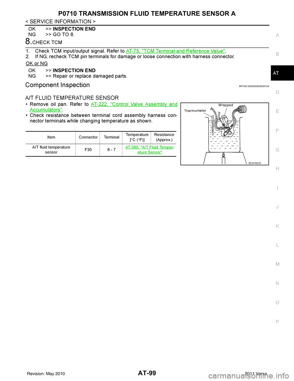
A/T FLUID TEMPERATURE SENSOR
• Remove oil pan. Refer to AT-222, "Control Valve Assembly and
Accumulators".
• Check resistance between terminal cord assembly harness con-
nector terminals while changing temperature as shown.
Item Connector Terminal Temperature
[° C ( °F)] Resistance
(Approx.)
A/T fluid temperature sensor F30 6 - 7
AT- 3 8 0 , "
A/T Fluid Temper-
ature Sensor"
SCIA7831E
Revision: May 2010
2011 Versa
Page 120 of 3787
P0720 OUTPUT SPEED SENSORAT-103
< SERVICE INFORMATION >
DE
F
G H
I
J
K L
M A
B
AT
N
O P
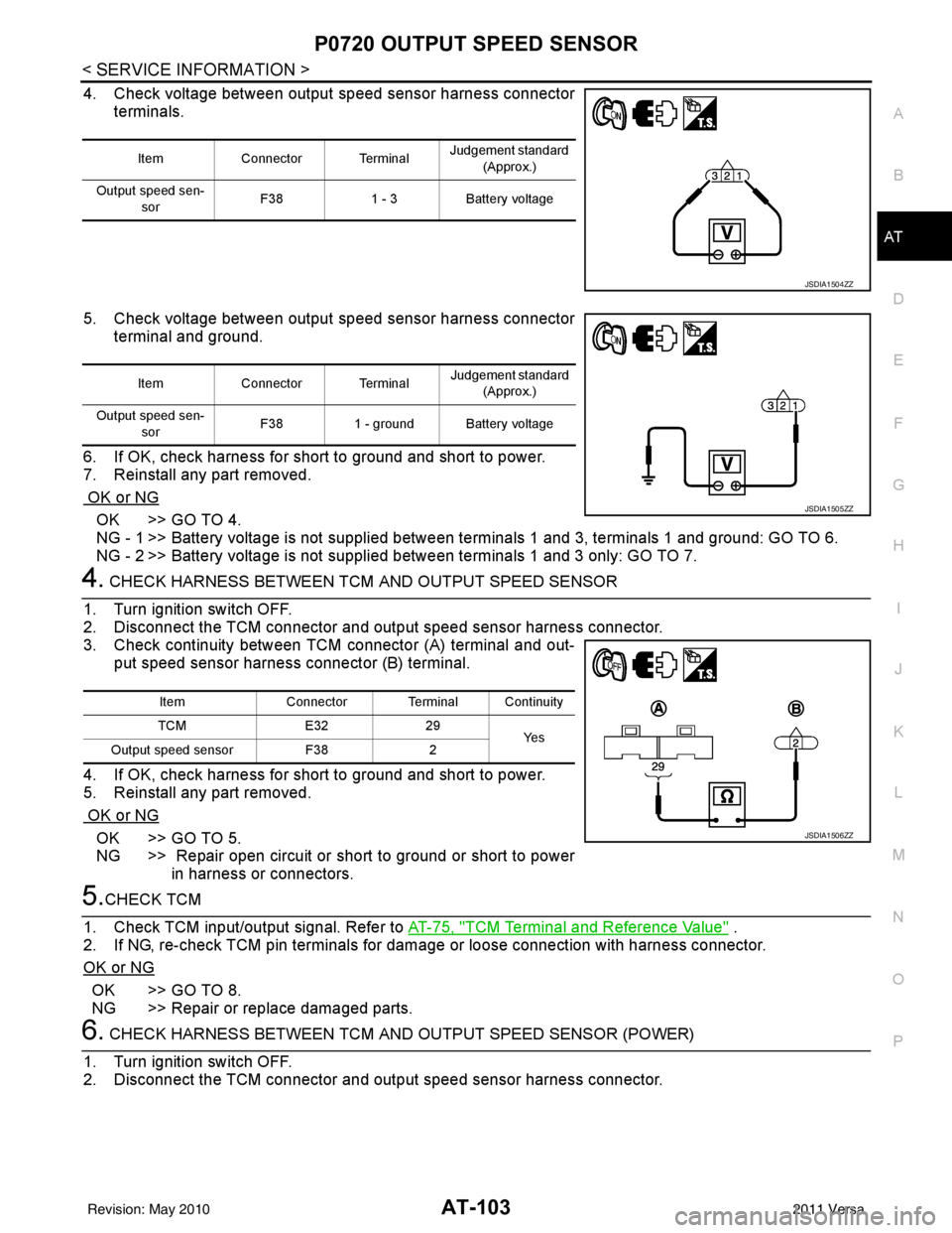
4. Check voltage between output speed sensor harness connector terminals.
5. Check voltage between output speed sensor harness connector terminal and ground.
6. If OK, check harness for short to ground and short to power.
7. Reinstall any part removed.
OK or NG
OK >> GO TO 4.
NG - 1 >> Battery voltage is not supplied between terminals 1 and 3, terminals 1 and ground: GO TO 6.
NG - 2 >> Battery voltage is not supplied between terminals 1 and 3 only: GO TO 7.
4. CHECK HARNESS BETWEEN TCM AND OUTPUT SPEED SENSOR
1. Turn ignition switch OFF.
2. Disconnect the TCM connector and output speed sensor harness connector.
3. Check continuity between TCM connector (A) terminal and out- put speed sensor harness connector (B) terminal.
4. If OK, check harness for short to ground and short to power.
5. Reinstall any part removed.
OK or NG
OK >> GO TO 5.
NG >> Repair open circuit or short to ground or short to power in harness or connectors.
5.CHECK TCM
1. Check TCM input/output signal. Refer to AT-75, "
TCM Terminal and Reference Value" .
2. If NG, re-check TCM pin terminals for dam age or loose connection with harness connector.
OK or NG
OK >> GO TO 8.
NG >> Repair or replace damaged parts.
6. CHECK HARNESS BETWEEN TCM AND OUTPUT SPEED SENSOR (POWER)
1. Turn ignition switch OFF.
2. Disconnect the TCM connector and output speed sensor harness connector.
Item Connector Terminal Judgement standard
(Approx.)
Output speed sen- sor F38
1 - 3Battery voltage
JSDIA1504ZZ
Item Connector Terminal Judgement standard
(Approx.)
Output speed sen- sor F38
1 - ground Battery voltage
JSDIA1505ZZ
Item Connector Terminal Continuity
TCM E3229
Ye s
Output speed sensor F382
JSDIA1506ZZ
Revision: May 2010 2011 Versa
Page 125 of 3787

AT-108
< SERVICE INFORMATION >
P0725 ENGINE SPEED
4.CHECK DTC
Perform AT-105, "
DTC Confirmation Procedure".
OK or NG
OK >> INSPECTION END
NG >> GO TO 5.
5.CHECK TCM
1. Check TCM input/output signal. Refer to AT-75, "
TCM Terminal and Reference Value".
2. If NG, recheck TCM pin terminals for damage or loose connection with harness connector.
OK or NG
OK >> INSPECTION END
NG >> Repair or replace damaged parts.
Revision: May 2010 2011 Versa
Page 127 of 3787
AT-110
< SERVICE INFORMATION >
P0731 1GR INCORRECT RATIO
5. Accelerate vehicle to 20 to 25 km/h (12 to 16 MPH) under the following conditions and release the accel-erator pedal completely.
THROTTLE POSI: Less than 1.0/8 (at all times during step 4)
SLCT LVR POSI: “D” position
- Make sure that “GEAR” shows “2” after releasing pedal.
6. Depress accelerator pedal to WOT (more than 7.0/8 of “THROTTLE POSI”) quickly from a speed of 20 to
25 km/h (12 to 16 MPH) until “TESTING” changes to “STOP VEHICLE” or “COMPLETED”. (It will take
approximately 3 seconds.)
If the check result NG appears on CONSULT-III screen, go to AT-110, "
Diagnosis Procedure".
If “STOP VEHICLE” appears on CONSULT- III screen, go to the following step.
- Make sure that “GEAR” shows “1” wh en depressing accelerator pedal to WOT.
- If “TESTING” does not appear on CONSULT-III fo r a long time, select “SELF-DIAG RESULTS” for
“TRANSMISSION”. In case a DTC other than “P0731 1GR INCORRECT RATIO” is shown, refer to
AT-77, "
CONSULT-III Funct ion (TRANSMISSION)".
7. Stop vehicle.
8. Follow the instruction displayed. (Check for normal shifting referring to the table below.)
9. Make sure that “OK” is displayed. (If “NG” is displayed, refer to “Diagnostic Procedure”.)
Refer to AT-110, "
Diagnosis Procedure".
Refer to AT-64, "
Vehicle Speed at Which Gear Shifting Occurs".
WITH GST
Follow the procedure “WITH CONSULT-III”.
Diagnosis ProcedureINFOID:0000000005928147
1.CHECK VALVE RESISTANCE
1. Remove control valve assembly. Refer to AT-222, "
Control Valve Assembly and Accumulators".
- Shift solenoid valve A
- Shift solenoid valve B
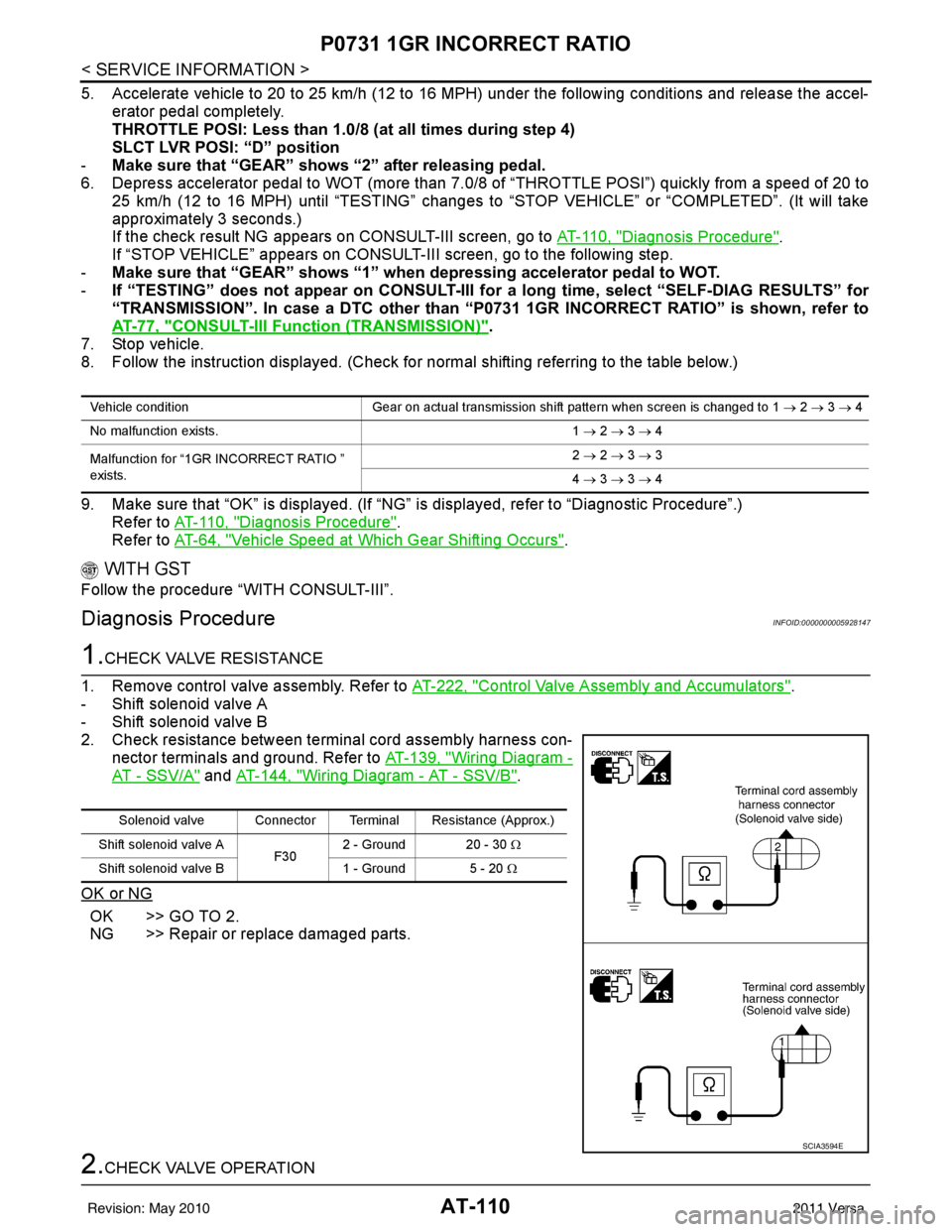
2. Check resistance between terminal cord assembly harness con- nector terminals and ground. Refer to AT-139, "
Wiring Diagram -
AT - SSV/A" and AT-144, "Wiring Diagram - AT - SSV/B".
OK or NG
OK >> GO TO 2.
NG >> Repair or replace damaged parts.
2.CHECK VALVE OPERATION
Vehicle condition Gear on actual transmission shift pattern when screen is changed to 1 → 2 → 3 → 4
No malfunction exists. 1 → 2 → 3 → 4
Malfunction for “1GR INCORRECT RATIO ”
exists. 2
→ 2 → 3 → 3
4 → 3 → 3 → 4
Solenoid valve Connector Terminal Resistance (Approx.)
Shift solenoid valve A F302 - Ground 20 - 30
Ω
Shift solenoid valve B 1 - Ground 5 - 20 Ω
SCIA3594E
Revision: May 2010 2011 Versa
Page 143 of 3787
AT-126
< SERVICE INFORMATION >
P0740 TORQUE CONVERTER
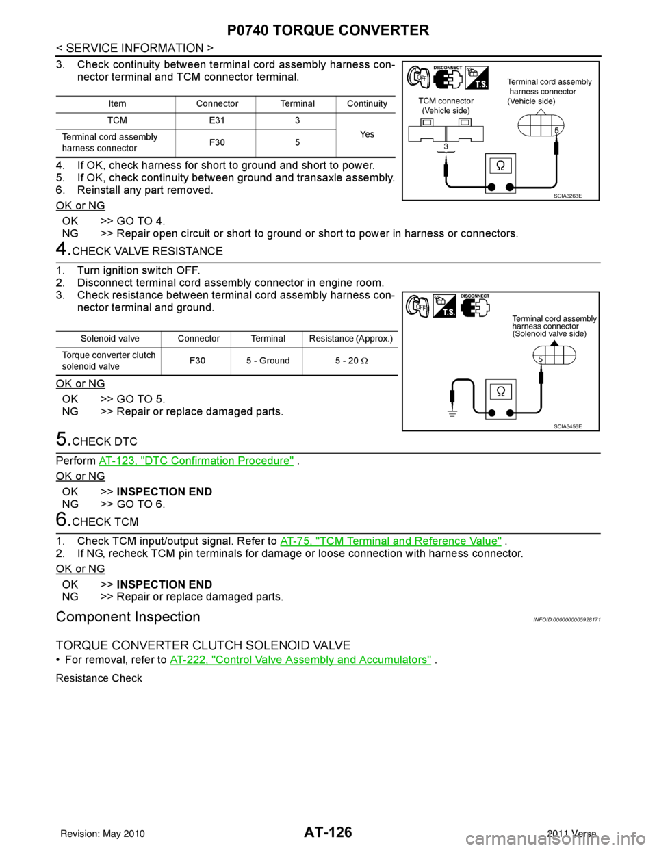
3. Check continuity between terminal cord assembly harness con-nector terminal and TCM connector terminal.
4. If OK, check harness for short to ground and short to power.
5. If OK, check continuity bet ween ground and transaxle assembly.
6. Reinstall any part removed.
OK or NG
OK >> GO TO 4.
NG >> Repair open circuit or short to ground or short to power in harness or connectors.
4.CHECK VALVE RESISTANCE
1. Turn ignition switch OFF.
2. Disconnect terminal cord assembly connector in engine room.
3. Check resistance between terminal cord assembly harness con- nector terminal and ground.
OK or NG
OK >> GO TO 5.
NG >> Repair or replace damaged parts.
5.CHECK DTC
Perform AT-123, "
DTC Confirmation Procedure" .
OK or NG
OK >> INSPECTION END
NG >> GO TO 6.
6.CHECK TCM
1. Check TCM input/output signal. Refer to AT-75, "
TCM Terminal and Reference Value" .
2. If NG, recheck TCM pin terminals for damage or loose connection with harness connector.
OK or NG
OK >> INSPECTION END
NG >> Repair or replace damaged parts.
Component InspectionINFOID:0000000005928171
TORQUE CONVERTER CLUTCH SOLENOID VALVE
• For removal, refer to AT-222, "Control Valve Assembly and Accumulators" .
Resistance Check
ItemConnector Terminal Continuity
TCM E313
Ye s
Terminal cord assembly
harness connector F30
5
SCIA3263E
Solenoid valve Connector Terminal Resistance (Approx.)
Torque converter clutch
solenoid valve F30 5 - Ground 5 - 20
Ω
SCIA3456E
Revision: May 2010 2011 Versa
Page 152 of 3787
P0745 PRESSURE CONTROL SOLENOID AAT-135
< SERVICE INFORMATION >
DE
F
G H
I
J
K L
M A
B
AT
N
O P
Diagnosis ProcedureINFOID:0000000005928184
1.CHECK INPUT SIGNALWith CONSULT-III
1. Turn ignition switch ON. (Do not start engine.)
2. Select “MAIN SIGNALS” in “DATA MONITOR” mode for “TRANSMISSION” with CONSULT-III.
3. Read out the value of “LINE PRES DTY” while driv ing. Check the value changes according to driving
speed.
Without CONSULT-III
1. Turn ignition switch ON. (Do not start engine.)
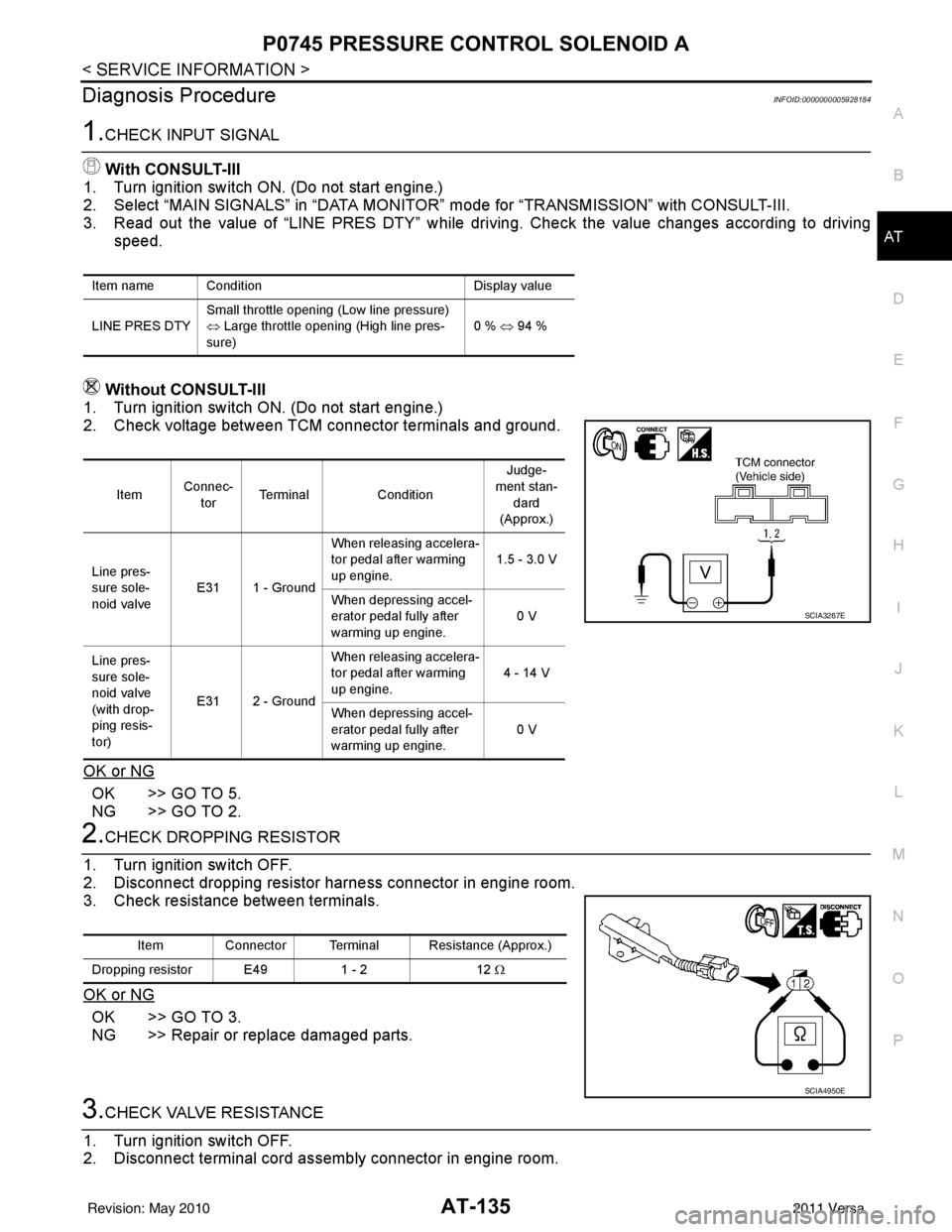
2. Check voltage between TCM connector terminals and ground.
OK or NG
OK >> GO TO 5.
NG >> GO TO 2.
2.CHECK DROPPING RESISTOR
1. Turn ignition switch OFF.
2. Disconnect dropping resistor har ness connector in engine room.
3. Check resistance between terminals.
OK or NG
OK >> GO TO 3.
NG >> Repair or replace damaged parts.
3.CHECK VALVE RESISTANCE
1. Turn ignition switch OFF.
2. Disconnect terminal cord assembly connector in engine room.
Item name Condition Display value
LINE PRES DTY Small throttle opening (Low line pressure)
⇔
Large throttle opening (High line pres-
sure) 0 % ⇔
94 %
Item Connec-
tor Terminal
Condition Judge-
ment stan- dard
(Approx.)
Line pres-
sure sole-
noid valve E31 1 - Ground When releasing accelera-
tor pedal after warming
up engine.
1.5 - 3.0 V
When depressing accel-
erator pedal fully after
warming up engine. 0 V
Line pres-
sure sole-
noid valve
(with drop-
ping resis-
tor) E31 2 - Ground When releasing accelera-
tor pedal after warming
up engine.
4 - 14 V
When depressing accel-
erator pedal fully after
warming up engine. 0 V
SCIA3267E
Item Connector Terminal Resistance (Approx.)
Dropping resistor E49 1 - 212 Ω
SCIA4950E
Revision: May 2010 2011 Versa