Page 348 of 3787
REPAIR FOR COMPONENT PARTSAT-331
< SERVICE INFORMATION >
DE
F
G H
I
J
K L
M A
B
AT
N
O P
• MR18DE engine models
CAUTION:
Roll paper around seal ring s to prevent seal rings from
spreading.
Band Servo Piston AssemblyINFOID:0000000005928301
COMPONENTS
HR16DE engine models
SCIA7996E
SCIA8011E
SCIA5891J
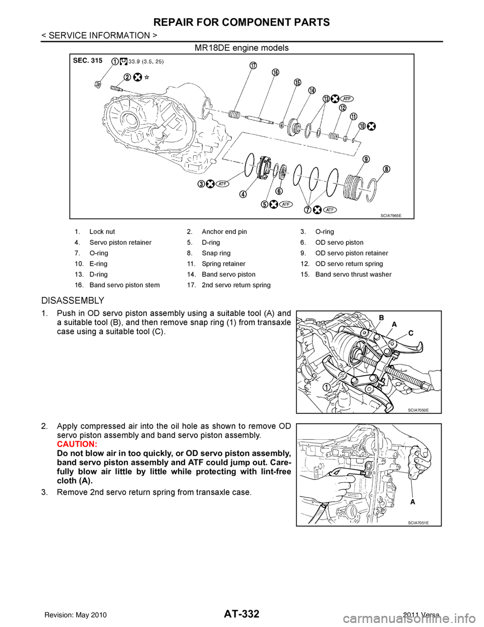
1. Lock nut 2. Anchor end pin 3. O-ring
4. Servo piston retainer 5. D-ring 6. OD servo piston
7. O-ring 8. Snap ring 9. OD servo piston retainer
10. E-ring 11. Spring retainer 12. OD servo return spring
13. D-ring 14. Band servo piston 15. Band servo thrust washer
16. Band servo piston stem 17. 2nd servo return spring
Revision: May 2010 2011 Versa
Page 349 of 3787

AT-332
< SERVICE INFORMATION >
REPAIR FOR COMPONENT PARTS
MR18DE engine models
DISASSEMBLY
1. Push in OD servo piston assembly using a suitable tool (A) anda suitable tool (B), and then remove snap ring (1) from transaxle
case using a suitable tool (C).
2. Apply compressed air into the oil hole as shown to remove OD servo piston assembly and band servo piston assembly.
CAUTION:
Do not blow air in too quickly, or OD servo piston assembly,
band servo piston assembly and ATF could jump out. Care-
fully blow air little by little while protecting with lint-free
cloth (A).
3. Remove 2nd servo return spring from transaxle case.
SCIA7965E
1. Lock nut 2. Anchor end pin 3. O-ring
4. Servo piston retainer 5. D-ring 6. OD servo piston
7. O-ring 8. Snap ring 9. OD servo piston retainer
10. E-ring 11. Spring retainer 12. OD servo return spring
13. D-ring 14. Band servo piston 15. Band servo thrust washer
16. Band servo piston stem 17. 2nd servo return spring
SCIA7050E
SCIA7051E
Revision: May 2010 2011 Versa
Page 351 of 3787
AT-334
< SERVICE INFORMATION >
REPAIR FOR COMPONENT PARTS
9. Remove spring retainer (1), OD servo return spring (2), bandservo piston (3) and band servo thrust washer (4) from band
servo piston stem (5).
10. Remove O-ring from servo piston retainer.
a. HR16DE engine models (1): O-ring (small diameter)
(2): O-ring (large diameter)
(3): Servo piston retainer
b. MR18DE engine models (1): O-ring
(2): Servo piston retainer
11. Remove D-rings from band servo piston.
INSPECTION
Pistons, Retainers and Piston Stem
Check the sliding surfaces for damage or excessive wear. Replace if necessary.
Return Springs
SCIA7054E
JPDIA0258ZZ
SCIA7967E
SCIA3688E
Revision: May 2010 2011 Versa
Page 353 of 3787
AT-336
< SERVICE INFORMATION >
REPAIR FOR COMPONENT PARTS
• HR16DE engine models
(1): O-ring (small diameter)
(2): O-ring (large diameter)
(3): Servo piston retainer
• MR18DE engine models(1): O-ring
(2): Servo piston retainer
5. Install band servo piston assembly to servo piston retainer by pushing it inward.
6. Install D-ring (1) to OD servo piston (2).
7. Install O-rings and to OD servo piston retainer. (1): O-ring (small diameter)
(2): O-ring (medium diameter)
(3): O-ring (large diameter)
(4): OD servo piston retainer
JPDIA0258ZZ
SCIA7967E
SAT303D
SCIA7053E
SCIA6492J
Revision: May 2010 2011 Versa
Page 355 of 3787
AT-338
< SERVICE INFORMATION >
REPAIR FOR COMPONENT PARTS
HR16DE engine modelsMR18DE models
DISASSEMBLY
SCIA7486E
1. Pinion mate gear thrust washer 2. Pinion mate gear 3. Pinion mate shaft
4. Side gear 5. Side gear thrust washer 6. Lock pin
7. Differential side bearing 8. Speedometer drive gear 9. Differential case
10. Final gear 11. Differential side bearing adjusting shim
SCIA7962E
1. Pinion mate gear 2. Pinion mate gear thrust washer 3. Pinion mate shaft
4. Lock pin 5. Side gear 6. Side gear thrust washer
7. Differential side bearing 8. Speedometer drive gear 9. Differential case
10. Final gear 11. Differential side bearing 12. Differential side bearing adjusting shim
Revision: May 2010 2011 Versa
Page 356 of 3787
REPAIR FOR COMPONENT PARTSAT-339
< SERVICE INFORMATION >
DE
F
G H
I
J
K L
M A
B
AT
N
O P
1. Remove final gear (1) from differential case (2).
2. Remove differential side bearings according to the following procedures.
a. HR16DE engine models
i. Set a suitable tool (A) on differential case (1), and remove differ- ential side bearing (RH side) (2) from differential case with suit-
able tool (B) and suitable tool (C).
ii. Set a suitable tool (A) on differential case (1), and remove differ- ential side bearing (LH side) (2) from differential case with suit-
able tool (B).
CAUTION:
Be careful not to mix up the right and left bearings.
b. MR18DE engine models
i. Set Tool on differential case, and remove differential side bear- ings from differential case using a suitable tool.
CAUTION:
Be careful not to mix up the right and left bearings.
SCIA8003E
SCIA7059E
SCIA7060E
Tool number : ST3306S001 (J-22888-D)
SAT312D
Revision: May 2010 2011 Versa
Page 359 of 3787

AT-342
< SERVICE INFORMATION >
REPAIR FOR COMPONENT PARTS
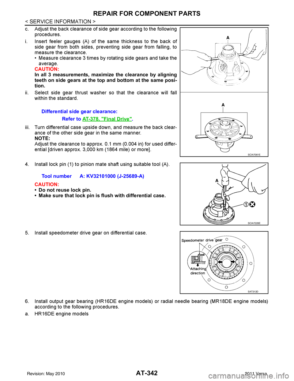
c. Adjust the back clearance of side gear according to the followingprocedures.
i. Insert feeler gauges (A) of the same thickness to the back of side gear from both sides, preventing side gear from falling, to
measure the clearance.
• Measure clearance 3 times by rotating side gears and take theaverage.
CAUTION:
In all 3 measurements, maximi ze the clearance by aligning
teeth on side gears at the top and bottom at the same posi-
tion.
ii. Select side gear thrust washer so that the clearance will fall within the standard.
iii. Turn differential case upside down, and measure the back clear- ance of the other side gear in the same manner.
NOTE:
Adjust the clearance to approx. 0.1 mm (0.004 in) for used differ-
ential [driven approx. 3,000 km (1864 mile) or more].
4. Install lock pin (1) to pinion mate shaft using suitable tool (A).
CAUTION:
• Do not reuse lock pin.
• Make sure that lock pin is flush with differential case.
5. Install speedometer drive gear on differential case.
6. Install output gear bearing (HR16DE engine models) or radial needle bearing (MR18DE engine models) according to the following procedures.
a. HR16DE engine models Differential side gear clearance:
Refer to AT-378, "
Final Drive".
SCIA7061E
Tool number A: KV32101000 (J-25689-A)
SCIA7228E
SAT313D
Revision: May 2010 2011 Versa
Page 360 of 3787

REPAIR FOR COMPONENT PARTSAT-343
< SERVICE INFORMATION >
DE
F
G H
I
J
K L
M A
B
AT
N
O P
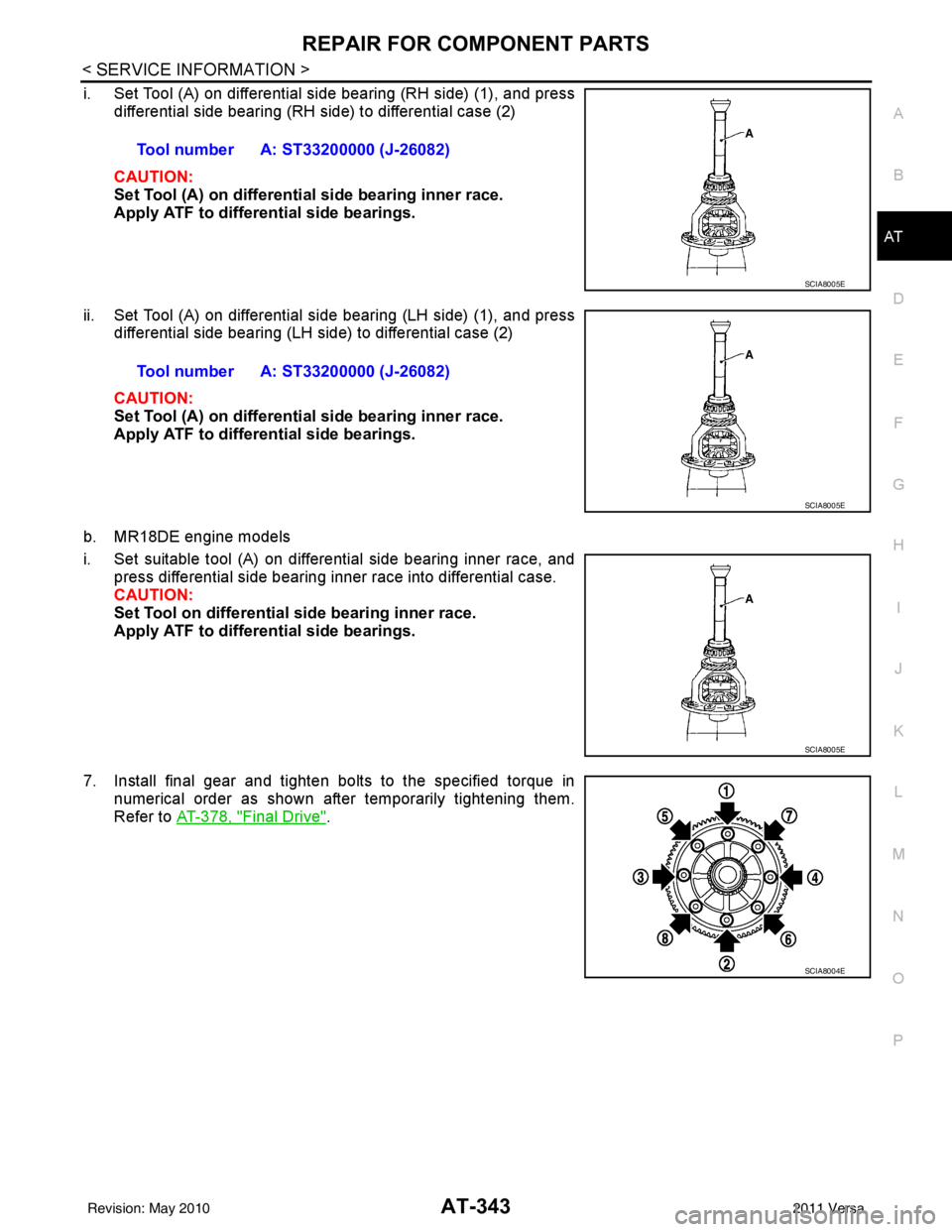
i. Set Tool (A) on differential side bearing (RH side) (1), and press differential side bearing (RH side) to differential case (2)
CAUTION:
Set Tool (A) on differential side bearing inner race.
Apply ATF to differential side bearings.
ii. Set Tool (A) on differential side bearing (LH side) (1), and press differential side bearing (LH side) to differential case (2)
CAUTION:
Set Tool (A) on differential side bearing inner race.
Apply ATF to differential side bearings.
b. MR18DE engine models
i. Set suitable tool (A) on differential side bearing inner race, and press differential side bearing inner race into differential case.
CAUTION:
Set Tool on differential side bearing inner race.
Apply ATF to differential side bearings.
7. Install final gear and tighten bolts to the specified torque in numerical order as shown after temporarily tightening them.
Refer to AT-378, "
Final Drive".
Tool number A: ST33200000 (J-26082)
SCIA8005E
Tool number A: ST33200000 (J-26082)
SCIA8005E
SCIA8005E
SCIA8004E
Revision: May 2010
2011 Versa