2011 NISSAN TIIDA nozzle
[x] Cancel search: nozzlePage 2546 of 3787
![NISSAN TIIDA 2011 Service Repair Manual EM-156
< SERVICE INFORMATION >[MR18DE]
FUEL INJECTOR AND FUEL TUBE
9. Remove fuel tube bolts.
• Loosen bolts in reverse order as shown.
10. Remove the fuel tube and fuel injector assembly. CAUTION:
NISSAN TIIDA 2011 Service Repair Manual EM-156
< SERVICE INFORMATION >[MR18DE]
FUEL INJECTOR AND FUEL TUBE
9. Remove fuel tube bolts.
• Loosen bolts in reverse order as shown.
10. Remove the fuel tube and fuel injector assembly. CAUTION:](/manual-img/5/57396/w960_57396-2545.png)
EM-156
< SERVICE INFORMATION >[MR18DE]
FUEL INJECTOR AND FUEL TUBE
9. Remove fuel tube bolts.
• Loosen bolts in reverse order as shown.
10. Remove the fuel tube and fuel injector assembly. CAUTION:
• When removing, be careful to avoid any interference with fuel injector.
• Use a shop cloth to absorb any fuel leaks from fuel tube.
11. Remove fuel injector from the f uel tube with the following procedure:
a. Open and remove the clip.
b. Remove fuel injector from the fuel tube by pulling straight. CAUTION:
• Be careful about spilling fu el remaining in fuel tube.
• Be careful not to damage the fuel injector nozzle during removal.
• Never bump or drop fuel injector.
• Never disassemble fuel injector.
INSTALLATION
1. Install new O-rings to the fuel injector.
CAUTION:
• The upper and lower O-rings are different. Be careful not to confuse them.
• Handle O-ring with bare hands. Never wear gloves.
• Lubricate O-ring with new engine oil.
• Never clean O-ring with solvent.
• Make sure that the O-ring and its mati ng part are free of foreign material.
• Be careful not to scratch O-ring with tool or fingernails when installing.
• Do not twist or stretch O-ring. If O-ring was stretched while installing, never insert it into fuel
tube immediately.
• Insert O-ring straight into fuel tube. Never angle or twist it.
: Engine front
PBIC3154J
Fuel tube side : Black
Nozzle side : Green
Revision: May 2010 2011 Versa
Page 2547 of 3787
![NISSAN TIIDA 2011 Service Repair Manual FUEL INJECTOR AND FUEL TUBEEM-157
< SERVICE INFORMATION > [MR18DE]
C
D
E
F
G H
I
J
K L
M A
EM
NP
O
2. Install fuel injector (4) to fuel tube (1) with the following proce-
dure:
a. Insert clip (2) into NISSAN TIIDA 2011 Service Repair Manual FUEL INJECTOR AND FUEL TUBEEM-157
< SERVICE INFORMATION > [MR18DE]
C
D
E
F
G H
I
J
K L
M A
EM
NP
O
2. Install fuel injector (4) to fuel tube (1) with the following proce-
dure:
a. Insert clip (2) into](/manual-img/5/57396/w960_57396-2546.png)
FUEL INJECTOR AND FUEL TUBEEM-157
< SERVICE INFORMATION > [MR18DE]
C
D
E
F
G H
I
J
K L
M A
EM
NP
O
2. Install fuel injector (4) to fuel tube (1) with the following proce-
dure:
a. Insert clip (2) into clip groove (F) on fuel injector. • Insert clip so that protrusion (G) of fuel injector matches cut-
out (D) of clip.
CAUTION:
• Never reuse clip. Replace it with a new one.
• Be careful to keep clip from interfering with O-ring. Ifinterference occurs, replace O-ring.
b. Insert fuel injector into fuel tube with clip attached. • Insert it while matching it to the axial center.
• Insert fuel injector so that protrusion (B) of fuel tube matches
cut-out (C) of clip.
• Make sure that fuel tube flange (A) is securely fixed in flange
fixing groove (E) on clip.
c. Make sure that installation is complete by making sure that fuel injector does not rotate or come off.
3. Set fuel tube and fuel injector assembly at its position for installation on cylinder head. CAUTION:
Be careful not to let tip of injector nozzle interfere with other parts.
4. Tighten bolts in numerical order as shown.
5. Installation of the remaining components is in the reverse order of removal.
InspectionINFOID:0000000006413287
INSPECTION AFTER INSTALLATION
• Before starting engine, check oil/fluid levels incl uding engine coolant and engine oil. If less than required
quantity, fill to the specified level. Refer to MA-14, "
Fluids and Lubricants".
• Use procedure below to check for fuel leakage.
• Turn ignition switch ON (with engine stopped). With fuel pressure applied to fuel piping, check for fuel leak- age at connection points.
• Start engine. With engine speed increased, check again for fuel leakage at connection points.
• Run engine to check for unusual noise and vibration.
• Warm up engine thoroughly to make sure there is no leak age of fuel, exhaust gas, or any oils/fluids including
engine oil and engine coolant.
• Bleed air from passages in lines and hoses, such as in cooling system.
• After cooling down engine, again check oil/fluid levels including engine oil and engine coolant. Refill to spec-
ified level, if necessary.
• Summary of the inspection items:
3 : O–ring (black)
5 : O–ring (green)
PBIC3155J
: Engine front
PBIC3154J
Revision: May 2010 2011 Versa
Page 2707 of 3787
PRECAUTIONSGI-3
< SERVICE INFORMATION >
C
DE
F
G H
I
J
K L
M B
GI
N
O P
2. Use the Intelligent Key or mechanical key to turn the ignition switch to the ″ACC ″ position. At this time, the
steering lock will be released.
3. Disconnect both battery cables. The steering lock will remain released and the steering wheel can be
rotated.
4. Perform the necessary repair operation.
5. When the repair work is completed, return the ignition switch to the ″LOCK ″ position before connecting
the battery cables. (At this time, the steering lock mechanism will engage.)
6. Perform a self-diagnosis check of al l control units using CONSULT-III.
General PrecautionINFOID:0000000005929711
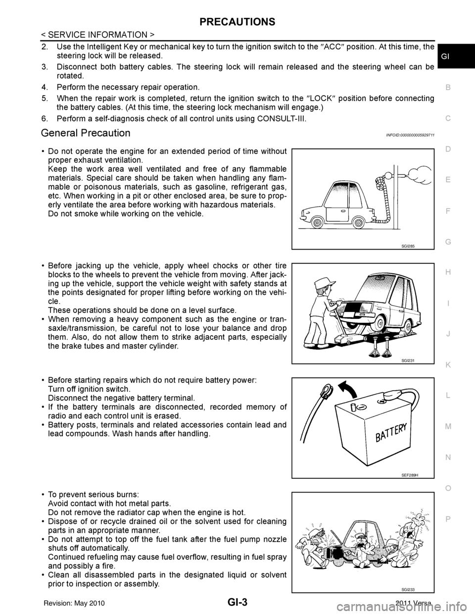
• Do not operate the engine for an extended period of time without
proper exhaust ventilation.
Keep the work area well ventilated and free of any flammable
materials. Special care should be taken when handling any flam-
mable or poisonous materials, such as gasoline, refrigerant gas,
etc. When working in a pit or ot her enclosed area, be sure to prop-
erly ventilate the area before working with hazardous materials.
Do not smoke while working on the vehicle.
• Before jacking up the vehicle, apply wheel chocks or other tire blocks to the wheels to prevent t he vehicle from moving. After jack-
ing up the vehicle, support the vehicle weight with safety stands at
the points designated for proper lifting before working on the vehi-
cle.
These operations should be done on a level surface.
• When removing a heavy component such as the engine or tran-
saxle/transmission, be careful not to lose your balance and drop
them. Also, do not allow them to strike adjacent parts, especially
the brake tubes and master cylinder.
• Before starting repairs which do not require battery power: Turn off ignition switch.
Disconnect the negative battery terminal.
• If the battery terminals are disconnected, recorded memory of
radio and each control unit is erased.
• Battery posts, terminals and related accessories contain lead and lead compounds. Wash hands after handling.
• To prevent serious burns: Avoid contact with hot metal parts.
Do not remove the radiator cap when the engine is hot.
• Dispose of or recycle drained oil or the solvent used for cleaning
parts in an appropriate manner.
• Do not attempt to top off the fuel tank after the fuel pump nozzle shuts off automatically.
Continued refueling may cause fuel overflow, resulting in fuel spray
and possibly a fire.
• Clean all disassembled parts in the designated liquid or solvent
prior to inspection or assembly.
SGI285
SGI231
SEF289H
SGI233
Revision: May 2010 2011 Versa
Page 3385 of 3787
DUCTS AND GRILLESMTC-69
< SERVICE INFORMATION >
C
DE
F
G H
I
K L
M A
B
MTC
N
O P
DUCTS AND GRILLES
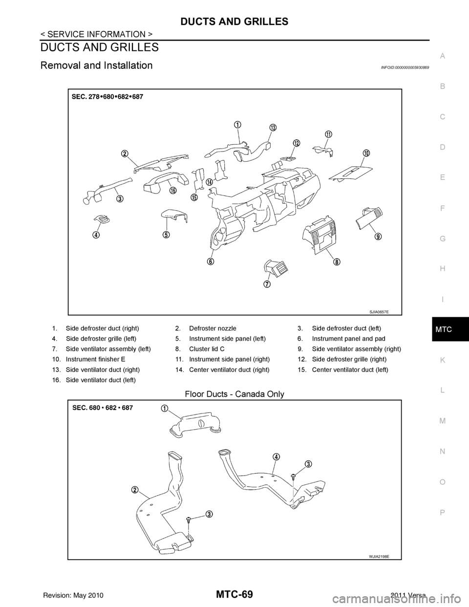
Removal and InstallationINFOID:0000000005930869
Floor Ducts - Canada Only
1. Side defroster duct (right) 2. Defroster nozzle3. Side defroster duct (left)
4. Side defroster grille (left) 5. Instrument side panel (left) 6. Instrument panel and pad
7. Side ventilator assembly (left) 8. Cluster lid C 9. Side ventilator assembly (right)
10. Instrument finisher E 11. Instrument side panel (right) 12. Side defroster grille (right)
13. Side ventilator duct (right) 14. Center ventilator duct (right) 15. Center ventilator duct (left)
16. Side ventilator duct (left)
SJIA0657E
WJIA2198E
Revision: May 2010 2011 Versa
Page 3386 of 3787
MTC-70
< SERVICE INFORMATION >
DUCTS AND GRILLES
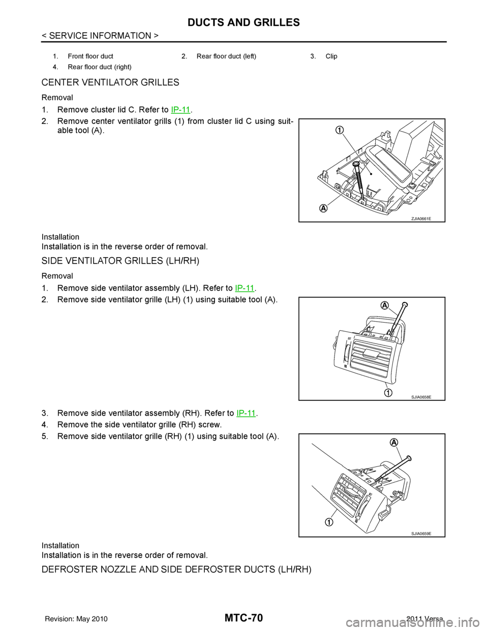
CENTER VENTILATOR GRILLES
Removal
1. Remove cluster lid C. Refer to IP-11.
2. Remove center ventilator grills (1) from cluster lid C using suit- able tool (A).
Installation
Installation is in the reverse order of removal.
SIDE VENTILATOR GRILLES (LH/RH)
Removal
1. Remove side ventilator assembly (LH). Refer to IP-11.
2. Remove side ventilator grille (LH) (1) using suitable tool (A).
3. Remove side ventilator assembly (RH). Refer to IP-11
.
4. Remove the side ventilator grille (RH) screw.
5. Remove side ventilator grille (RH) (1) using suitable tool (A).
Installation
Installation is in the reverse order of removal.
DEFROSTER NOZZLE AND SIDE DEFROSTER DUCTS (LH/RH)
1. Front floor duct 2. Rear floor duct (left) 3. Clip
4. Rear floor duct (right)
ZJIA0661E
SJIA0658E
SJIA0659E
Revision: May 2010 2011 Versa
Page 3387 of 3787
DUCTS AND GRILLESMTC-71
< SERVICE INFORMATION >
C
DE
F
G H
I
K L
M A
B
MTC
N
O P
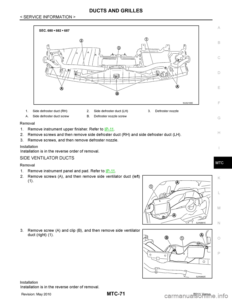
Removal
1. Remove instrument upper finisher. Refer to
IP-11.
2. Remove screws and then remove side defro ster duct (RH) and side defroster duct (LH).
3. Remove screws, and then remove defroster nozzle.
Installation
Installation is in the reverse order of removal.
SIDE VENTILATOR DUCTS
Removal
1. Remove instrument panel and pad. Refer to IP-11.
2. Remove screws (A), and then remove side ventilator duct (left) (1).
3. Remove screw (A) and clip (B), and then remove side ventilator duct (right) (1).
Installation
Installation is in the reverse order of removal.
1. Side defroster duct (RH) 2. Side defroster duct (LH)3. Defroster nozzle
A. Side defroster duct screw B. Defroster nozzle screw
WJIA2199E
SJIA0661E
SJIA0662E
Revision: May 2010 2011 Versa
Page 3747 of 3787
WW-1
ELECTRICAL
C
DE
F
G H
I
J
L
M
SECTION WW
A
B
WW
N
O P
CONTENTS
WIPER, WASHER & HORN
SERVICE INFORMATION .. ..........................2
PRECAUTION ................................................ .....2
Precaution for Supplemental Restraint System
(SRS) "AIR BAG" and "SEAT BELT PRE-TEN-
SIONER" ............................................................. ......
2
Precaution Necessary for Steering Wheel Rota-
tion After Battery Disconnect ............................... ......
2
Precaution for Procedure without Cowl Top Cover ......3
PREPARATION ...................................................4
Special Service Tool ........................................... ......4
FRONT WIPER AND WASHER SYSTEM ..........5
Component Parts and Harness Connector Loca-
tion ...................................................................... ......
5
System Description ...................................................5
CAN Communication System Description .................7
Schematic .................................................................8
Wiring Diagram - WIPER - ........................................9
Terminal and Reference Value for BCM .................12
Terminal and Reference Value for IPDM E/R .........12
How to Proceed with Trouble Diagnosis .................12
Preliminary Check ...................................................12
CONSULT-III Function (BCM) .................................12
CONSULT-III Function (IPDM E/R) .........................13
Front Wiper Does Not Operate ...............................14
Front Wiper Does Not Return to Stop Position (Af-
ter Front Wiper Operates for 10 Seconds, They
Stop for 20 Seconds, and After Repeating the Op-
eration Five Times, They Become Inoperative) ......
16
Only Front Wiper Low Does Not Operate ...............17
Only Front Wiper High Does Not Operate ...............18
Only Front Wiper Intermittent Does Not Operate ....19
Front Wiper Intermittent Operation Switch Posi-
tion Cannot Be Adjusted .........................................
20
Wiper Does Not Wipe When Front Washer Oper-
ates .........................................................................
20
Front Wiper Does Not Stop .....................................20
Removal and Installation of Front Wiper Arms ........20
Adjustment of Wiper Arm Stop Location .............. ....21
Removal and Installation of Front Wiper Drive As-
sembly .....................................................................
22
Removal and Installation of Front Washer Nozzle ....22
Inspection for Washer Nozzle ..................................23
Washer Nozzle Adjustment ................................. ....24
Washer Tube Layout ...............................................24
Removal and Installation of Front Wiper and
Washer Switch .........................................................
25
Inspection of Front Wiper and Washer Switch Cir-
cuit ...........................................................................
25
Removal and Installation of Washer Tank ...............25
Removal and Installation of Front Washer Motor ....26
REAR WIPER AND WASHER SYSTEM ..........27
Component Parts and Harness Connector Loca-
tion ....................................................................... ....
27
System Description ..................................................27
Wiring Diagram - WIP/R - ........................................29
Terminal and Reference Value for BCM ..................31
How to Proceed with Trou ble Diagnosis ..................31
Preliminary Check ............................................... ....31
CONSULT-III Function (BCM) .................................31
Rear Wiper Does Not Operate ............................ ....31
Rear Wiper Stop Position Is Incorrect .....................33
Only Rear Wiper Does Not Operate ........................34
Only Rear Wiper Intermittent Does Not Operate .....34
Wiper Does Not Wipe When Rear Washer Oper-
ates ..........................................................................
34
Removal and Installation .........................................34
Washer Nozzle Adjustment .....................................37
POWER SOCKET .............................................38
Wiring Diagram - P/SCKT - .....................................38
Removal and Installation .........................................38
HORN ................................................................40
Wiring Diagram - HORN - ........................................40
Removal and Installation .........................................40
Revision: May 2010 2011 Versa
Page 3768 of 3787
WW-22
< SERVICE INFORMATION >
FRONT WIPER AND WASHER SYSTEM
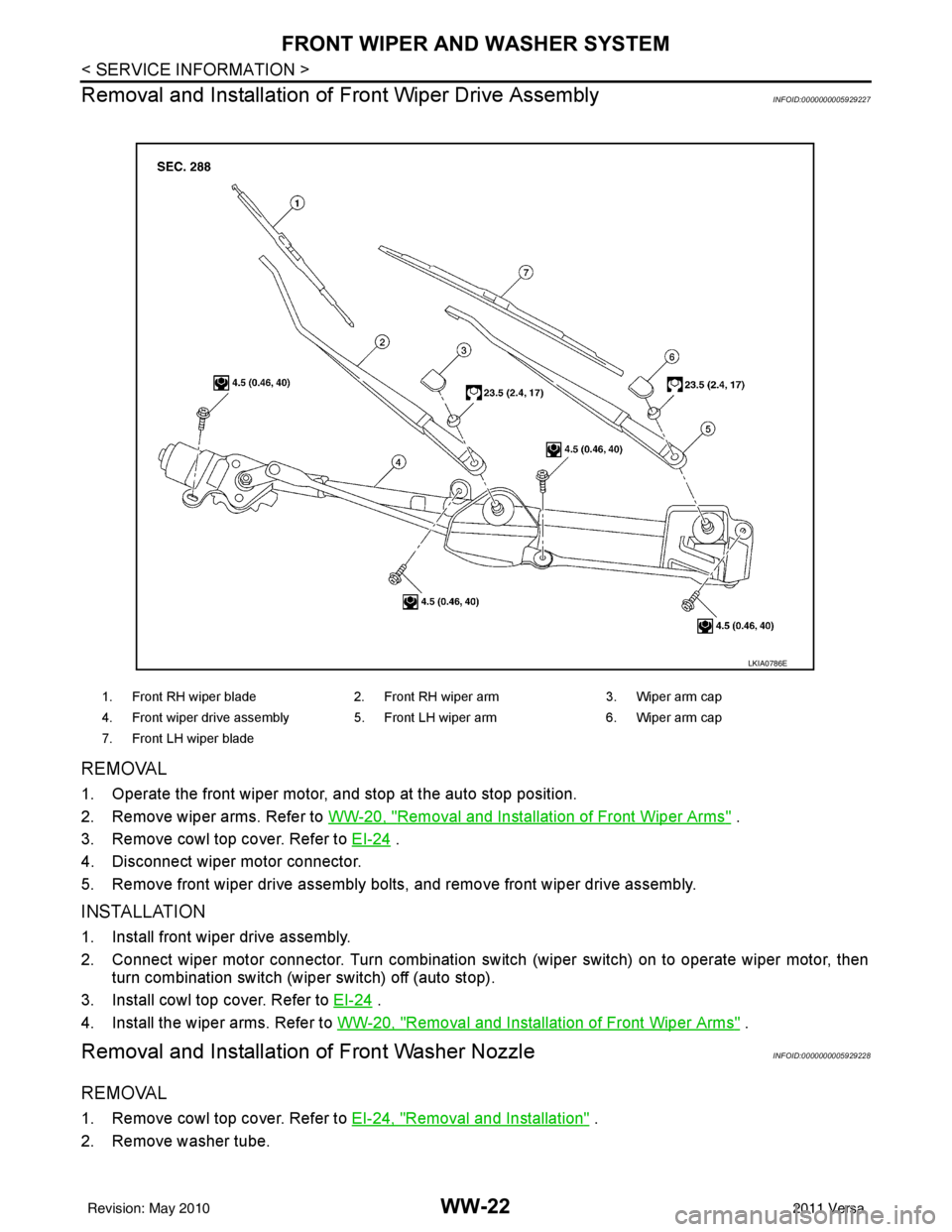
Removal and Installation of Front Wiper Drive Assembly
INFOID:0000000005929227
REMOVAL
1. Operate the front wiper motor, and stop at the auto stop position.
2. Remove wiper arms. Refer to WW-20, "
Removal and Installation of Front Wiper Arms" .
3. Remove cowl top cover. Refer to EI-24
.
4. Disconnect wiper motor connector.
5. Remove front wiper drive assembly bolts, and remove front wiper drive assembly.
INSTALLATION
1. Install front wiper drive assembly.
2. Connect wiper motor connector. Turn combination switch (wiper switch) on to operate wiper motor, then turn combination switch (wiper switch) off (auto stop).
3. Install cowl top cover. Refer to EI-24
.
4. Install the wiper arms. Refer to WW-20, "
Removal and Installation of Front Wiper Arms" .
Removal and Installation of Front Washer NozzleINFOID:0000000005929228
REMOVAL
1. Remove cowl top cover. Refer to EI-24, "Removal and Installation" .
2. Remove washer tube.
1. Front RH wiper blade 2. Front RH wiper arm 3. Wiper arm cap
4. Front wiper drive assembly 5. Front LH wiper arm 6. Wiper arm cap
7. Front LH wiper blade
LKIA0786E
Revision: May 2010 2011 Versa