2011 NISSAN TIIDA Motor oil spec
[x] Cancel search: Motor oil specPage 1666 of 3787
![NISSAN TIIDA 2011 Service Repair Manual EC-372
< COMPONENT DIAGNOSIS >[HR16DE]
P1217 ENGINE OVER TEMPERATURE
P1217 ENGINE OVER TEMPERATURE
DTC LogicINFOID:0000000005930041
DTC DETECTION LOGIC
NOTE:
•
If DTC P1217 is displayed with DTC UX](/manual-img/5/57396/w960_57396-1665.png "NISSAN TIIDA 2011 Service Repair Manual EC-372
< COMPONENT DIAGNOSIS >[HR16DE]
P1217 ENGINE OVER TEMPERATURE
P1217 ENGINE OVER TEMPERATURE
DTC LogicINFOID:0000000005930041
DTC DETECTION LOGIC
NOTE:
•
If DTC P1217 is displayed with DTC UX")
EC-372
< COMPONENT DIAGNOSIS >[HR16DE]
P1217 ENGINE OVER TEMPERATURE
P1217 ENGINE OVER TEMPERATURE
DTC LogicINFOID:0000000005930041
DTC DETECTION LOGIC
NOTE:
•
If DTC P1217 is displayed with DTC UXXXX, first perform the trouble diagnosis for DTC UXXXX.
• If DTC P1217 is displayed with DTC P0607, first perform the trouble diagno sis for DTC P0607. Refer
to EC-361, "
DTC Logic".
If the cooling fan or another component in the cooling system malfunctions, engine coolant temperature will
rise.
When the engine coolant temperature reaches an abnorma lly high temperature condition, a malfunction is
indicated.
CAUTION:
When a malfunction is indicated, be sure to replace the coolant. Refer to CO-11, "
Changing Engine
Coolant". Also, replace the engine oil. Refer to LU-8, "Draining" and LU-8, "Refilling".
1. Fill radiator with coolant up to specified level with a filling speed of 2 liters per minute. Be sure to use coolant with the proper mixture ratio. Refer to MA-15, "
Anti-freeze Coolant Mixture Ratio".
2. After refilling coolant, run engine to en sure that no water-flow noise is emitted.
DTC CONFIRMATION PROCEDURE
1.PERFORM COMPONENT FUNCTION CHECK
Perform component function check. Refer to EC-372, "
Component Function Check".
NOTE:
Use component function check to check the overall function of the cooling fan. During this check, a DTC might
not be confirmed.
Is the inspection result normal?
YES >> INSPECTION END
NO >> Go to EC-373, "
Diagnosis Procedure".
Component Function CheckINFOID:0000000005930042
1.PERFORM COMPONENT FUNCTION CHECK-I
WARNING:
Never remove the radiator cap when the engine is hot. Serious burns could be caused by high pres-
sure fluid escaping from the radiator.
Wrap a thick cloth around cap. Carefully remove the cap by turning it a quarter turn to allow built-up
pressure to escape. Then turn the cap all the way off.
DTC No. Trouble diagnosis name DTC detecting conditionPossible cause
P1217 Engine over temperature
(Overheat) • Cooling fan does not operate properly (Over-
heat).
• Cooling fan system does not operate properly (Overheat).
• Engine coolant was not added to the system using the proper filling method.
• Engine coolant is not within the specified range. • Harness or connectors
(The cooling fan circuit is open or
shorted.)
• IPDM E/R (Cooling fan relay-1)
• Cooling fan relays-2 and -3
• Cooling fan motor
•Radiator hose
•Radiator
•Radiator cap
• Reservoir tank
• Water pump
•Thermostat
• Water control valve
Revision: May 2010 2011 Versa
Page 2475 of 3787
![NISSAN TIIDA 2011 Service Repair Manual ENGINE ASSEMBLYEM-85
< REMOVAL AND INSTALLATION > [HR16DE]
C
D
E
F
G H
I
J
K L
M A
EM
NP
O
4. Remove engine mounting insulator (RH) (1), engine mounting
bracket (RH) (2) and engine mounting stay (3).](/manual-img/5/57396/w960_57396-2474.png "NISSAN TIIDA 2011 Service Repair Manual ENGINE ASSEMBLYEM-85
< REMOVAL AND INSTALLATION > [HR16DE]
C
D
E
F
G H
I
J
K L
M A
EM
NP
O
4. Remove engine mounting insulator (RH) (1), engine mounting
bracket (RH) (2) and engine mounting stay (3).")
ENGINE ASSEMBLYEM-85
< REMOVAL AND INSTALLATION > [HR16DE]
C
D
E
F
G H
I
J
K L
M A
EM
NP
O
4. Remove engine mounting insulator (RH) (1), engine mounting
bracket (RH) (2) and engine mounting stay (3).
5. Remove engine mounting insulator (LH) (4) through bolt secur- ing nut (A).
6. Carefully lower jack, or raise lift to remove the engine and the transaxle assembly. CAUTION:
• Make sure that no part interferes with the vehicle side.
• Before and during this lifting, alw ays check if any harnesses are left connected.
• During the removal, always be careful to prevent the vehicle from falling off the lift due to
changes in the center of gravity.
• If necessary, support the vehicle by setting jack or suitable tool at the rear.
Separation
1. Remove starter motor. Refer to SC-19, "Removal and Installation HR16DE".
2. Lift with a hoist and separate the engine from the transaxle assembly. Refer to EM-82, "
Exploded View".
INSTALLATION
Installation is in the reverse order of removal.
• Do not allow engine oil to get on engine mounting insulator. Be careful not to damage engine mounting insu-
lator.
• Make sure that each mounting insulator is seated properly, and tighten nuts and bolts.
• Tighten engine mounting insulator (RH) bolts in the numerical
order shown.
InspectionINFOID:0000000005930964
INSPECTION AFTER INSTALLATION
• Before starting engine, check oil/fluid levels incl uding engine coolant and engine oil. If less than required
quantity, fill to the specified level. Refer to MA-14, "
Fluids and Lubricants".
• Use procedure below to check for fuel leakage.
• Turn ignition switch ON (with engine stopped). With fuel pressure applied to fuel piping, check for fuel leak-
age at connection points.
• Start engine. With engine speed increased, check again for fuel leakage at connection points.
• Run engine to check for unusual noise and vibration.
• Warm up engine thoroughly to make sure there is no leak age of fuel, exhaust gas, or any oils/fluids including
engine oil and engine coolant.
• Bleed air from passages in lines and hoses, such as in cooling system.
• After cooling down engine, again check oil/fluid levels including engine oil and engine coolant. Refill to spec- ified level, if necessary.
• Summary of the inspection items:
JPBIA0512ZZ
: Vehicle front
JPBIA0280ZZ
Item Before starting engine Engine runningAfter engine stopped
Engine coolant LevelLeakage Level
Revision: May 2010 2011 Versa
Page 3046 of 3787

LT-14
< SERVICE INFORMATION >
HEADLAMP (FOR USA)
x: Applicable
NOTE:
The details for display of the period are as follows:
• CRNT: Error currently detected with IPDM E/R.
• PAST: Error detected in the past and placed in IPDM E/R memory.
DATA MONITOR
All Signals, Main Signals, Selection From Menu
Display itemsCONSULT-
III display code Malfunction detection TIME
Possible causes
CRNT PAST
NO DTC IS DETECTED.
FURTHER TESTING
MAY BE REQUIRED. —————
CAN COMM CIRC U1000 • If CAN communication reception/transmission
data has a malfunction, or if any of the control
units fail, data reception/transmission cannot be
confirmed.
• When the data in CAN communication is not re-
ceived before the specified time. XX
Any of items listed
below have errors:
• TRANSMIT DIAG
•ECM
• BCM/SEC
IGN RELAY ON —When the ignition switch is not in the ON position,
the ignition relay in the IPDM E/R is ON. XX
Ignition relay (inte-
grated in IPDM E/R)
IGN RELAY OFF —When the ignition switch is not in the ON position,
the ignition relay in the IPDM E/R is OFF. XXIgnition relay (inte-
grated in IPDM E/R)
EEPROM —Malfunction is de
tected with the integrated EEPROM
memory diagnosis. X X IPDM E/R
Item nameCONSULT-III
screen display Display or unit Monitor item selection
Description
ALL
SIGNALS MAIN
SIGNALS SELECTION
FROM MENU
Motor fan request MOTOR FAN
REQ1/2/3/4
X X X Signal status input from ECM
Compressor re-
quest AC COMP REQ ON/OFF
X XX Signal status input from ECM
Parking, license,
and tail lamp re-
quest TAIL & CLR REQ ON/OFF
X XX Signal status input from BCM
Headlamp low
beam request HL LO REQ ON/OFF
X XX Signal status input from BCM
Headlamp high
beam request HL HI REQ ON/OFF
X XX Signal status input from BCM
Front fog request FR FOG REQ ON/OFF X XX Signal status input from BCM
FR wiper request FR WIP REQ STOP/1LO/LO/HI X X X Signal status input from BCM
Wiper auto stop WIP AUTO
STOPACT P/STOP P X X
X Output status of IPDM E/R
Wiper protection WIP PROT OFF/LS/HS/Block X X X Control status of IPDM E/R
Starter request ST RLY REQ ON/OFF XX Status of input signal (*1)
Ignition relay
status IGN RLY ON/OFF
X XXIgnition relay status monitored
with IPDM E/R
Rear defogger re-
quest RR DEF REQ ON/OFF
X XX Signal status input from BCM
Oil pressure
switch OIL P SW OPEN/CLOSE X
XSignal status input from IPDM
E/R
Hood switch HOOD SW (*2) OFF XXSignal status input from IPDM
E/R
Revision: May 2010
2011 Versa
Page 3339 of 3787
TROUBLE DIAGNOSISMTC-23
< SERVICE INFORMATION >
C
DE
F
G H
I
K L
M A
B
MTC
N
O P
WORK SUPPORT
Display Item List
How to Perform Trouble Diagnosis for Quick and Accurate RepairINFOID:0000000005930843
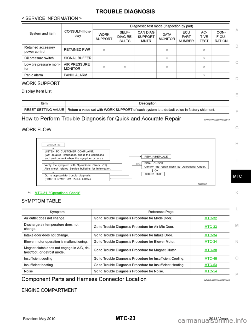
WORK FLOW
SYMPTOM TABLE
Component Parts and Har ness Connector LocationINFOID:0000000005930844
ENGINE COMPARTMENT
Retained accessory
power controlRETAINED PWR
×× ×
Oil pressure switch SIGNAL BUFFER ××
Low tire pressure moni-
tor AIR PRESSURE
MONITOR
××
× ×
Panic alarm PANIC ALARM ×
System and item
CONSULT-III dis-
play Diagnostic test mode (Inspection by part)
WORK
SUPPORT SELF
−
DIAG RE-
SULTS CAN DIAG
SUPPORT
MNTR DATA
MONITOR ECU
PA R T
NUMBER AC-
TIVE
TEST CON-
FIGU-
RATION
Item Description
RESET SETTING VALUE Return a value set with WORK SUPPORT of each system to a default value in factory shipment.
*1 MTC-31, "Operational Check"
SHA900E
Symptom Reference Page
Air outlet does not change. Go to Trouble Diagnosis Procedure for Mode Door. MTC-32
Discharge air temperature does not
change.Go to Trouble Diagnosis Procedure for Air Mix Door.
MTC-33
Intake door does not change.Go to Trouble Diagnosis Procedure for Intake Door. MTC-34
Blower motor operation is malfunctioning. Go to Trouble Diagnosis Procedure for Blower Motor. MTC-34
Magnet clutch does not engage in A/C, de-
frost/foot, or defrost mode.Go to Trouble Diagnosis Procedure for Magnet Clutch.
MTC-38
Insufficient coolingGo to Trouble Diagnosis Procedure for Insufficient Cooling. MTC-46
Insufficient heatingGo to Trouble Diagnosis Procedure for Insufficient Heating. MTC-53
NoiseGo to Trouble Diagnosis Procedure for Noise. MTC-54
Revision: May 2010 2011 Versa
Page 3368 of 3787
MTC-52
< SERVICE INFORMATION >
TROUBLE DIAGNOSIS
Both High- and Low-pressure Sides are Too Low
Low-pressure Side Sometimes Becomes Negative
Low-pressure Side Becomes Negative
Gauge indication Refrigerant cycle Probable causeCorrective action
Both high- and low-pressure
sides are too low. • There is a big temperature dif-
ference between liquid tank
outlet and inlet. Outlet tem-
perature is extremely low.
• Liquid tank inlet and expan- sion valve are frosted. Liquid tank inside is slightly
clogged.
• Replace liquid tank.
• Check oil for contamination.
• Temperature of expansion valve inlet is extremely low as
compared with areas near liq-
uid tank.
• Expansion valve inlet may be
frosted.
• Temperature difference oc- curs somewhere in high-pres-
sure side. High-pressure pipe located be-
tween liquid tank and expansion
valve is clogged.
• Check and repair malfunc-
tioning parts.
• Check oil for contamination.
Expansion valve and liquid tank
are warm or only cool when
touched. Low refrigerant charge.
↓
Leaking fittings or componentsCheck refrigerant for leaks.
Refer to
MTC-92, "
Checking of
Refrigerant Leaks" .
There is a big temperature dif-
ference between expansion
valve inlet and outlet while the
valve itself is frosted. Expansion valve closes a little
compared with the specification.
↓
1. Improper expansion valve
adjustment.
2. Malfunctioning expansion valve.
3. Outlet and inlet may be clogged. • Remove foreign particles by
using compressed air.
• Replace expansion valve.
• Check oil for contamination.
An area of the low-pressure pipe
is colder than areas near the
evaporator outlet. Low-pressure pipe is clogged or
crushed.• Check and repair malfunc-
tioning parts.
• Check oil for contamination.
Air flow volume is not enough or
is too low. Evaporator is frozen.• Check thermo control amp.
Refer to MTC-38, "
Magnet
Clutch Circuit (If Equipped)"
.
• Replace compressor.
• Repair evaporator fins.
• Replace evaporator.
•Refer to MTC-34, "
Front
Blower Motor Circuit" .
AC353A
Gauge indication Refrigerant cycleProbable causeCorrective action
Low-pressure side sometimes be-
comes negative. • Air conditioning system does
not function and does not cy-
clically cool the compart-
ment air.
• The system constantly func-
tions for a certain period of
time after compressor is
stopped and restarted. Refrigerant does not discharge
cyclically.
↓
Moisture is frozen at expan-
sion valve outlet and inlet.
↓
Water is mixed with refrigerant.
• Drain water from refrigerant
or replace refrigerant.
• Replace liquid tank.
AC354A
Revision: May 2010 2011 Versa
Page 3439 of 3787

IPDM E/R (INTELLIGENT POWER DISTRIBUTION MODULE ENGINE ROOM)
PG-19
< SERVICE INFORMATION >
C
D E
F
G H
I
J
L
M A
B
PG
N
O P
x: Applicable
NOTE:
The details for display of the period are as follows:
• CRNT: Error currently detected with IPDM E/R.
• PAST: Error detected in the past and placed in IPDM E/R memory.
DATA MONITOR
All Signals, Main Signals, Selection From Menu
Display items CONSULT-
III display code Malfunction detection TIME
Possible causes
CRNT PAST
NO DTC IS DETECTED.
FURTHER TESTING
MAY BE REQUIRED. ———
——
CAN COMM CIRC U1000 • If CAN communication reception/transmission
data has a malfunction, or if any of the control
units fail, data reception/transmission cannot be
confirmed.
• When the data in CAN communication is not re-
ceived before the specified time. XX
Any of items listed
below have
errors:
• TRANSMIT DIAG
•ECM
• BCM/SEC
IGN RELAY ON —When the ignition switch is not in the ON position,
the ignition relay in the IPDM E/R is ON. XX
Ignition relay (inte-
grated in IPDM E/R)
IGN RELAY OFF —When the ignition switch is not in the ON position,
the ignition relay in the IPDM E/R is OFF. XXIgnition relay (inte-
grated in IPDM E/R)
EEPROM —Malfunction is detected with the integrated EEPROM
memory diagnosis.
X X IPDM E/R
Item nameCONSULT-III
screen display Display or unit Monitor item selection
Description
ALL
SIGNALS MAIN
SIGNALS SELECTION
FROM MENU
Motor fan request MOTOR FAN
REQ1/2/3/4
X X X Signal status input from ECM
Compressor re-
quest AC COMP REQ ON/OFF
X XX Signal status input from ECM
Parking, license,
and tail lamp re-
quest TAIL & CLR REQ ON/OFF
X XX Signal status input from BCM
Headlamp low
beam request HL LO REQ ON/OFF
X XX Signal status input from BCM
Headlamp high
beam request HL HI REQ ON/OFF
X XX Signal status input from BCM
Front fog request FR FOG REQ ON/OFF X XX Signal status input from BCM
FR wiper request FR WIP REQ STOP/1LO/LO/HI X X X Signal status input from BCM
Wiper auto stop WIP AUTO
STOPACT P/STOP P X X
X Output status of IPDM E/R
Wiper protection WIP PROT OFF/LS/HS/Block X X X Control status of IPDM E/R
Starter request ST RLY REQ ON/OFF XX Status of input signal (*1)
Ignition relay
status IGN RLY ON/OFF
X XXIgnition relay status monitored
with IPDM E/R
Rear defogger re-
quest RR DEF REQ ON/OFF
X XX Signal status input from BCM
Oil pressure
switch OIL P SW OPEN/CLOSE X
XSignal status input from IPDM
E/R
Hood switch HOOD SW (*2) OFF XXSignal status input from IPDM
E/R
Revision: May 2010
2011 Versa
Page 3442 of 3787
PG-22
< SERVICE INFORMATION >
IPDM E/R (INTELLIGENT POWER DISTRIBUTION MODULE ENGINE ROOM)
Concept of Auto Active Test
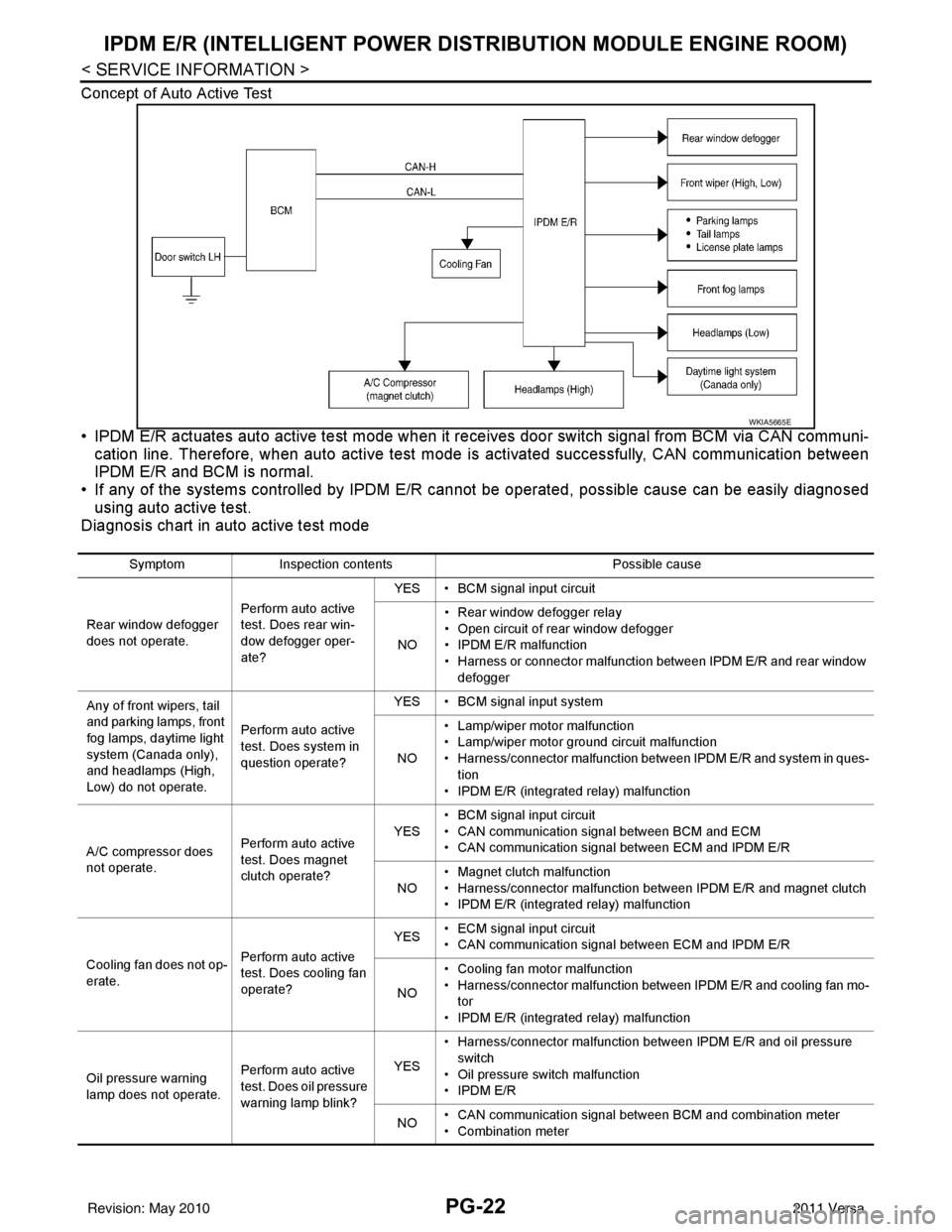
• IPDM E/R actuates auto active test mode when it re ceives door switch signal from BCM via CAN communi-
cation line. Therefore, when auto active test mode is activated successfully, CAN communication between
IPDM E/R and BCM is normal.
• If any of the systems controll ed by IPDM E/R cannot be operated, possible cause can be easily diagnosed
using auto active test.
Diagnosis chart in auto active test mode
WKIA5665E
Symptom Inspection contents Possible cause
Rear window defogger
does not operate. Perform auto active
test. Does rear win-
dow defogger oper-
ate?YES • BCM signal input circuit
NO • Rear window defogger relay
• Open circuit of rear window defogger
•IPDM E/R malfunction
• Harness or connector malfunction between IPDM E/R and rear window
defogger
Any of front wipers, tail
and parking lamps, front
fog lamps, daytime light
system (Canada only),
and headlamps (High,
Low) do not operate. Perform auto active
test. Does system in
question operate?YES • BCM signal input system
NO • Lamp/wiper motor malfunction
• Lamp/wiper motor ground circuit malfunction
• Harness/connector malfunction between IPDM E/R and system in ques-
tion
• IPDM E/R (integrated relay) malfunction
A/C compressor does
not operate. Perform auto active
test. Does magnet
clutch operate?YES
• BCM signal input circuit
• CAN communication signal between BCM and ECM
• CAN communication signal between ECM and IPDM E/R
NO • Magnet clutch malfunction
• Harness/connector malfunction between IPDM E/R and magnet clutch
• IPDM E/R (integrated relay) malfunction
Cooling fan does not op-
erate. Perform auto active
test. Does cooling fan
operate?YES
• ECM signal input circuit
• CAN communication signal between ECM and IPDM E/R
NO • Cooling fan motor malfunction
• Harness/connector malfunction between IPDM E/R and cooling fan mo-
tor
• IPDM E/R (integrated relay) malfunction
Oil pressure warning
lamp does not operate. Perform auto active
test. Does oil pressure
warning lamp blink?YES
• Harness/connector malfunction between IPDM E/R and oil pressure
switch
• Oil pressure switch malfunction
•IPDM E/R
NO • CAN communication signal between BCM and combination meter
• Combination meter
Revision: May 2010
2011 Versa
Page 3446 of 3787

PG-26
< SERVICE INFORMATION >
IPDM E/R (INTELLIGENT POWER DISTRIBUTION MODULE ENGINE ROOM)
24 Y Cooling fan relay-3 Output — Conditions correct for cooling
fan high operation
Battery voltage
Conditions not correct for
cooling fan high operation 0V
26 O Tail lamp relay (park-
ing lamps) Output — Lighting switch in 2nd position Battery voltage
27 BR Tail lamp relay (park-
ing lamps)
Output — Lighting switch in 2nd position Battery voltage
28 GR Tail lamp relay (park-
ing lamps) Output — Lighting switch in 2nd position Battery voltage
29 P Tail lamp relay (park-
ing lamps) Output — Lighting switch in 2nd position Battery voltage
30
(A/T
only) R Fuse 54
Output —Ignition switch ON or START
Battery voltage
Ignition switch OFF or ACC 0V
31 O Fuse 55 Output —Ignition switch ON or START
Battery voltage
Ignition switch OFF or ACC 0V
32 L Wiper high speed sig-
nal
OutputON or
START Wiper switch OFF, LO, INT
0V
HI Battery voltage
33 Y Wiper low speed sig-
nal
OutputON or
START Wiper switch OFF
0V
LO or INT Battery voltage
35 BR Starter relay (inhibit
switch) InputON or
START Selector lever in "P" or "N"
(CVT or A/T) or clutch pedal
depressed (M/T)
Battery voltage
Selector lever any other posi-
tion (CVT or A/T) or clutch
pedal released (M/T) 0V
36 BR Fuel pump relay Output — Ignition switch ON or START
Battery voltage
Ignition switch OFF or ACC 0V
37 G Oil pressure switch Input ON or
START Engine running and oil pres-
sure within specification
Battery voltage
Engine not running or oil pres-
sure below specification 0V
38 R Wiper auto stop signal Input ON or
START Wipers not in park position
Battery voltage
Wipers in park position 0V
39 B Ground Input ——0V
40 P CAN-L — ON— —
41 L CAN-H — ON— —
45 R Horn relay control Input — Horn switch PUSHED, alarm
switch activated or door lock/
unlock is confirmed when op-
erating lock system via the
keyfob
0V
Horn switch released, alarm
not active, keyfob not active Battery voltage
46 Y Throttle control motor
relay control Input —Ignition switch ON or START
0V
Ignition switch OFF or ACC Battery voltage
47 GR Fuel pump relay con-
trol Input —Ignition switch ON or START
0V
Ig niti
on switch OFF or ACC Battery voltage
Te r m i n a l
Wire
color Signal name Signal
input/
output Measuring condition
Reference value
(Approx.)
Ignition
switch Operation or condition
Revision: May 2010
2011 Versa