2011 NISSAN TIIDA Instrument Panel
[x] Cancel search: Instrument PanelPage 600 of 3787

BL-90
< SERVICE INFORMATION >
INTELLIGENT KEY SYSTEM
* : Hatchback
** : Sedan
KEY REMINDER FUNCTION
Key reminder functions have the following 2 functions.
CAUTION:
• The above function operates when the Intelligent Key is inside the vehicle. However, there may be
times when the Intelligent Key cannot be detected, an d this function will not operate when the Intelli-
gent Key is on the instrument panel, rear parcel shelf or in the glove box. Also, this system some-
times does not operate if the Intelligent Key is in the door pocket of an open door.
List of Operation Related Parts
Parts marked with × are the parts related to operation
REMOTE KEYLESS ENTRY FUNCTIONS
The Intelligent Key has the same functions as the remote keyless entry system. T herefore, it can be used in
the same manner as the keyfob by operating the door lock/unlock button.
Door lock open function
Intelligent Key
Key switch
Ignition knob switch
Door switch
Back door lock assembly (back door switch)
*
Request switch (driver, passenger, back)
Door lock actuator
Inside key antenna
Outside key antenna
Intelligent Key warning buzzer (front door LH)
Intelligent Key warning buzzer (trunk)
**
Intelligent Key unit
CAN communication system
BCM
Hazard warning lamp
Door lock/unlock function by request switch ××××××××××
Door lock/unlock function by mechanical key ××
Hazard and buzzer reminder function ××××××
Auto door lock function ×××× × ×××
Key reminder functionOperation condition Operation
Door is open to close Right after all doors are closed under the following conditions.
• Intelligent Key is inside the vehicle
• Any door is opened
• All doors are locked by door lock and unlock switch or door
lock knob • All doors unlock operation
• Sound Intelligent Key warn-
ing buzzer for 3 seconds
Key reminder functions
Intelligent Key
Door switch
Unlock sensor
Door lock actuator
Inside key antenna
Intelligent Key warning buzzer(s)
Intelligent Key unit
CAN communication system
BCM
Any door open to close ×××××××××
Revision: May 2010 2011 Versa
Page 618 of 3787
BL-108
< SERVICE INFORMATION >
INTELLIGENT KEY SYSTEM
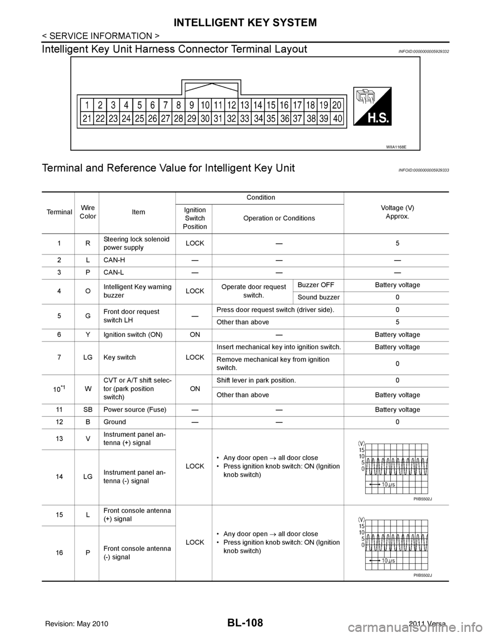
Intelligent Key Unit Harnes s Connector Terminal Layout
INFOID:0000000005929332
Terminal and Reference Value for Intelligent Key UnitINFOID:0000000005929333
WIIA1168E
Te r m i n a lWire
Color Item Condition
Voltage (V)Approx.
Ignition
Switch
Position Operation or Conditions
1R Steering lock solenoid
power supply LOCK
— 5
2 L CAN-H —— —
3 P CAN-L —— —
4O Intelligent Key warning
buzzer LOCK
Operate door request
switch. Buzzer OFF
Battery voltage
Sound buzzer 0
5G Front door request
switch LH —Press door request switch (driver side).
0
Other than above 5
6 Y Ignition switch (ON) ON —Battery voltage
7 LG Key switch LOCKInsert mechanical key into ignition switch. Battery voltage
Remove mechanical key from ignition
switch.
0
10
*1W CVT or A/T shift selec-
tor (park position
switch)
ONShift lever in park position.
0
Other than above Battery voltage
11 SB Power source (Fuse) — —Battery voltage
12 B Ground —— 0
13 V Instrument panel an-
tenna (+) signal
LOCK• Any door open
→ all door close
• Press ignition knob switch: ON (Ignition knob switch)
14 LG Instrument panel an-
tenna (-) signal
15 L Front console antenna
(+) signal
LOCK• Any door open
→ all door close
• Press ignition knob switch: ON (Ignition knob switch)
16 P Front console antenna
(-) signal
PIIB5502J
PIIB5502J
Revision: May 2010
2011 Versa
Page 628 of 3787
![NISSAN TIIDA 2011 Service Repair Manual BL-118
< SERVICE INFORMATION >
INTELLIGENT KEY SYSTEM
*: Select “SELECTION FROM MENU”.
ACTIVE TEST
* : Sedan
WORK SUPPORT
BD/TR REQ SWIndicates [ON/OFF] condition of back door request switch.
IGN NISSAN TIIDA 2011 Service Repair Manual BL-118
< SERVICE INFORMATION >
INTELLIGENT KEY SYSTEM
*: Select “SELECTION FROM MENU”.
ACTIVE TEST
* : Sedan
WORK SUPPORT
BD/TR REQ SWIndicates [ON/OFF] condition of back door request switch.
IGN](/manual-img/5/57396/w960_57396-627.png)
BL-118
< SERVICE INFORMATION >
INTELLIGENT KEY SYSTEM
*: Select “SELECTION FROM MENU”.
ACTIVE TEST
* : Sedan
WORK SUPPORT
BD/TR REQ SWIndicates [ON/OFF] condition of back door request switch.
IGN SW Indicates [ON/OFF] condition of ignition switch in ON position.
ACC SW Indicates [ON/OFF] condition of ignition switch in ACC position.
STOP LAMP SW Indicates [ON/OFF] condition of stop lamp switch.
P RANGE SW Indicates [ON/OFF] condition of shift lever park position.
BD OPEN SW Indicates [ON/OFF] condition of back door open switch.
DOOR LOCK SIG* Indicates [ON/OFF] condition of door lock signal from Intelligent Key button.
DOOR UNLOCK SIG* Indicates [ON/OFF] condition of door unlock signal from Intelligent Key button
KEYLESS PANIC* Indicates [ON/OFF] condition of panic signal from Intelligent Key button
DOOR SW DR* Indicates [OPEN/CLOSE] condition of front door sw
itch driver side from BCM via CAN communica-
tion line.
DOOR SW AS* Indicates [OPEN/CLOSE] condition of front door switch passenger side from BCM via CAN commu-
nication line.
DOOR SW RR* Indicates [OPEN/CLOSE] condition of rear door switch RH from BCM via CAN communication line.
DOOR SW RL* Indicates [OPEN/CLOSE] condition of rear door switch LH from BCM via CAN communication line.
VEHICLE SPEED* Indicates [km/h] condition of vehicle speed.
Monitor item
Content
Te s t i t e mD e s c r i p t i o n
DOOR LOCK/UNLOCK This test is able to check door lock/unlock operation.
• The all door lock actuators are unlocked when “ALL UNLK” on CONSULT-III screen is touched.
• The all door lock actuators are locked when “LOCK” on CONSULT-III screen is touched.
ANTENNA This test is able to check Intelligent Key antenna operation.
When the following conditions are met, hazard warning lamps flash.
• Inside key antenna (front console) detects Intelligent Key, when “ROOM ANT1” on CONSULT-
III screen is touched.
• Inside key antenna (instrument panel and rear floor) detects Intelligent Key, when “ROOM
ANT2” on CONSULT-III screen is touched.
• Outside key antenna (driver side) detects Intelligent Key, when “DR ANT” on CONSULT-III screen is touched.
• Outside key antenna (passenger side) detects Intelligent Key, when “AS ANT” on CONSULT-III screen is touched.
• Outside key antenna (rear bumper) detects Intelligent Key, when “BK DR ANT” on CONSULT- III screen is touched.
OUTSIDE BUZZER This test is able to check Intelligent Key warning buzzer operation.
Intelligent Key warning buzzer sounds when “ON” on CONSULT-III screen is touched.
INSIDE BUZZER This test is able to check Intelligent Key warning chime (Instrument panel) operation.
• Take away warning chime sounds when “TAKE OUT” on CONSULT-III screen is touched.
• Ignition switch warning chime sounds when “KNOB” on CONSULT-III screen is touched.
• Ignition key warning chime sounds when “KEY” on CONSULT-III screen is touched.
INDICATOR This test is able to check warning lamp operation.
• “KEY” Warning lamp (Green) illuminates when “BLUE ON” on CONSULT-III screen is touched.
• “KEY” Warning lamp (Red) illuminates when
“RED ON” on CONSULT-III screen is touched.
• “LOCK” Warning lamp illuminates when “KNOB ON” on CONSULT-III screen is touched.
• “KEY” Warning lamp (Green) flashes when “BLUE IND” on CONSULT-III screen is touched.
• “KEY” Warning lamp (RED) flashes when “RED IND” on CONSULT-III screen is touched.
• “P-SHIFT” Warning lamp flashes when “KNOB IND” on CONSULT-III screen is touched.
Revision: May 2010 2011 Versa
Page 656 of 3787
BL-146
< SERVICE INFORMATION >
INTELLIGENT KEY SYSTEM
OK or NG
OK >> Replace rear bumper antenna.
NG >> Replace Intelligent Key unit. Refer to BL-158, "
Removal and Installation of Intelligent Key Unit".
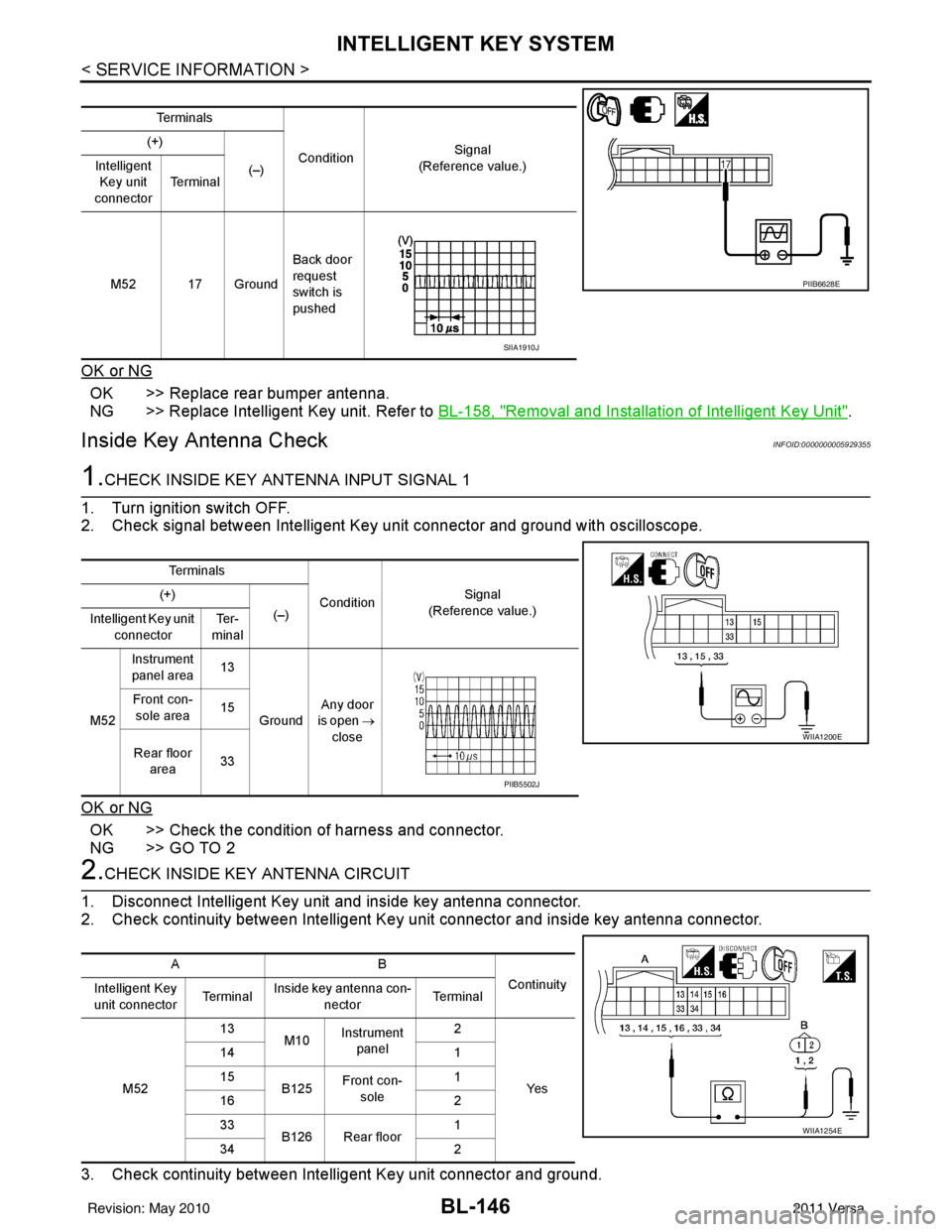
Inside Key Antenna CheckINFOID:0000000005929355
1.CHECK INSIDE KEY ANTENNA INPUT SIGNAL 1
1. Turn ignition switch OFF.
2. Check signal between Intelligent Key unit connector and ground with oscilloscope.
OK or NG
OK >> Check the condition of harness and connector.
NG >> GO TO 2
2.CHECK INSIDE KEY ANTENNA CIRCUIT
1. Disconnect Intelligent Key unit and inside key antenna connector.
2. Check continuity between Intelligent Key unit connector and inside key antenna connector.
3. Check continuity between Intelligent Key unit connector and ground.
Te r m i n a l s
Condition Signal
(Reference value.)
(+)
(–)
Intelligent
Key unit
connector Te r m i n a l
M52 17 Ground Back door
request
switch is
pushed
PIIB6628E
SIIA1910J
Te r m i n a l s
ConditionSignal
(Reference value.)
(+)
(–)
Intelligent Key unit
connector Te r -
minal
M52 Instrument
panel area 13
Ground Any door
is open →
close
Front con-
sole area 15
Rear floor area 33
WIIA1200E
PIIB5502J
AB
Continuity
Intelligent Key
unit connector Te r m i n a lInside key antenna con-
nector Te r m i n a l
M52 13
M10Instrument
panel 2
Ye s
14
1
15 B125Front con-
sole 1
16 2
33 B126 Rear floor 1
34 2
WIIA1254E
Revision: May 2010 2011 Versa
Page 657 of 3787
INTELLIGENT KEY SYSTEMBL-147
< SERVICE INFORMATION >
C
DE
F
G H
J
K L
M A
B
BL
N
O P
OK or NG
OK >> GO TO 3
NG >> Repair or replace harness between Intelligent Key unit and inside key antenna.
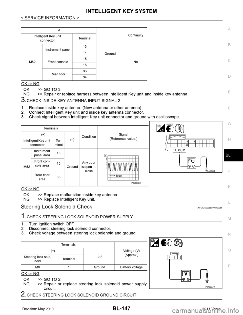
3.CHECK INSIDE KEY ANTENNA INPUT SIGNAL 2
1. Replace inside key antenna. (New antenna or other antenna)
2. Connect Intelligent Key unit and inside key antenna connector.
3. Check signal between Intelligent Key unit connector and ground with oscilloscope.
OK or NG
OK >> Replace malfunction inside key antenna.
NG >> Replace Intelligent Key unit.
Steering Lock Solenoid CheckINFOID:0000000005929356
1.CHECK STEERING LOCK SOLENOID POWER SUPPLY
1. Turn ignition switch OFF.
2. Disconnect steering lock solenoid connector.
3. Check voltage between steering lock solenoid and ground.
OK or NG
OK >> GO TO 2
NG >> Repair or replace steering lock solenoid power supply circuit.
2.CHECK STEERING LOCK SOLENOID GROUND CIRCUIT
A
GroundContinuity
Intelligent Key unit
connector Te r m i n a l
M52 Instrument panel
13
No
14
Front console 15
16
Rear floor 33
34
Te r m i n a l s
ConditionSignal
(Reference value.)
(+)
(–)
Intelligent Key unit
connector Te r -
minal
M52 Instrument
panel area 13
Ground Any door
is open →
close
Front con-
sole area 15
Rear floor area 33
WIIA1200E
PIIB5502J
Te r m i n a l s
Voltage (V)(Approx.)
(+)
(–)
Steering lock sole-
noid Te r m i n a l
M6 1Ground Battery voltage
PIIB6632E
Revision: May 2010 2011 Versa
Page 691 of 3787
BACK DOOR LOCKBL-181
< SERVICE INFORMATION >
C
DE
F
G H
J
K L
M A
B
BL
N
O P
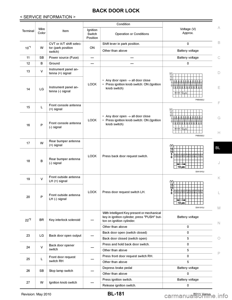
10*1W CVT or A/T shift selec-
tor (park position
switch)
ONShift lever in park position.
0
Other than above Battery voltage
11 SB Power source (Fus e) — —Battery voltage
12 B Ground —— 0
13 V Instrument panel an-
tenna (+) signal
LOCK• Any door open
→ all door close
• Press ignition knob switch: ON (Ignition knob switch)
14 LG Instrument panel an-
tenna (-) signal
15 L Front console antenna
(+) signal
LOCK• Any door open
→ all door close
• Press ignition knob switch: ON (Ignition knob switch)
16 P Front console antenna
(-) signal
17 W Rear bumper antenna
(+) signal
LOCK Press back door request switch.
18 B Rear bumper antenna
(-) signal
19 V Front outside antenna
LH (+) signal
LOCK Press door request switch LH.
20 P Front outside antenna
LH (-) signal
22
*2BR Key interlock solenoid — With Intelligent Key present or mechanical
key in ignition cylinder, press "PUSH" but-
ton on ignition cylinder.
Battery voltage
Other than above 0
23 LG Back door open output — Back door open (switch closed)
0
Back door closed (switch open) 5
24 V Back door opener
switch —Press and hold back door switch.
0
Other than above 5
25 L Front door request
switch RH
—Press front door request switch RH.
0
Other than above 5
26 SB Stop lamp switch —Depress brake pedal
Battery voltage
Other than above 0
27 W Ignition knob switch — Press ignition switch.
Battery voltage
Release ignition switch. 0
Terminal
Wire
Color Item Condition
Voltage (V)Approx.
Ignition
Switch
Position Operation or Conditions
PIIB5502J
PIIB5502J
SIIA1910J
SIIA1910J
Revision: May 2010
2011 Versa
Page 716 of 3787
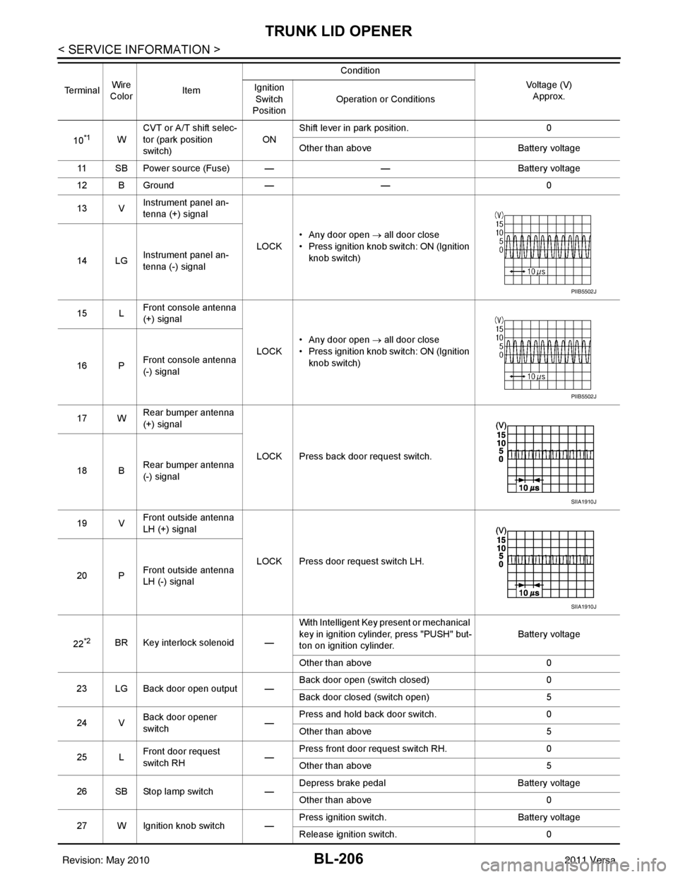
BL-206
< SERVICE INFORMATION >
TRUNK LID OPENER
10*1WCVT or A/T shift selec-
tor (park position
switch)
ONShift lever in park position.
0
Other than above Battery voltage
11 SB Power source (Fuse) — —Battery voltage
12 B Ground —— 0
13 V Instrument panel an-
tenna (+) signal
LOCK• Any door open
→ all door close
• Press ignition knob switch: ON (Ignition knob switch)
14 LG Instrument panel an-
tenna (-) signal
15 L Front console antenna
(+) signal
LOCK• Any door open
→ all door close
• Press ignition knob switch: ON (Ignition knob switch)
16 P Front console antenna
(-) signal
17 W Rear bumper antenna
(+) signal
LOCK Press back door request switch.
18 B Rear bumper antenna
(-) signal
19 V Front outside antenna
LH (+) signal
LOCK Press door request switch LH.
20 P Front outside antenna
LH (-) signal
22
*2BR Key interlock solenoid — With Intelligent Key present or mechanical
key in ignition cylinder, press "PUSH" but-
ton on ignition cylinder.
Battery voltage
Other than above 0
23 LG Back door open output — Back door open (switch closed)
0
Back door closed (switch open) 5
24 V Back door opener
switch —Press and hold back door switch.
0
Other than above 5
25 L Front door request
switch RH
—Press front door request switch RH.
0
Other than above 5
26 SB Stop lamp switch —Depress brake pedal
Battery voltage
Other than above 0
27 W Ignition knob switch — Press ignition switch.
Battery voltage
Release ignition switch. 0
Te r m i n a l
Wire
Color Item Condition
Voltage (V)Approx.
Ignition
Switch
Position Operation or Conditions
PIIB5502J
PIIB5502J
SIIA1910J
SIIA1910J
Revision: May 2010
2011 Versa
Page 741 of 3787
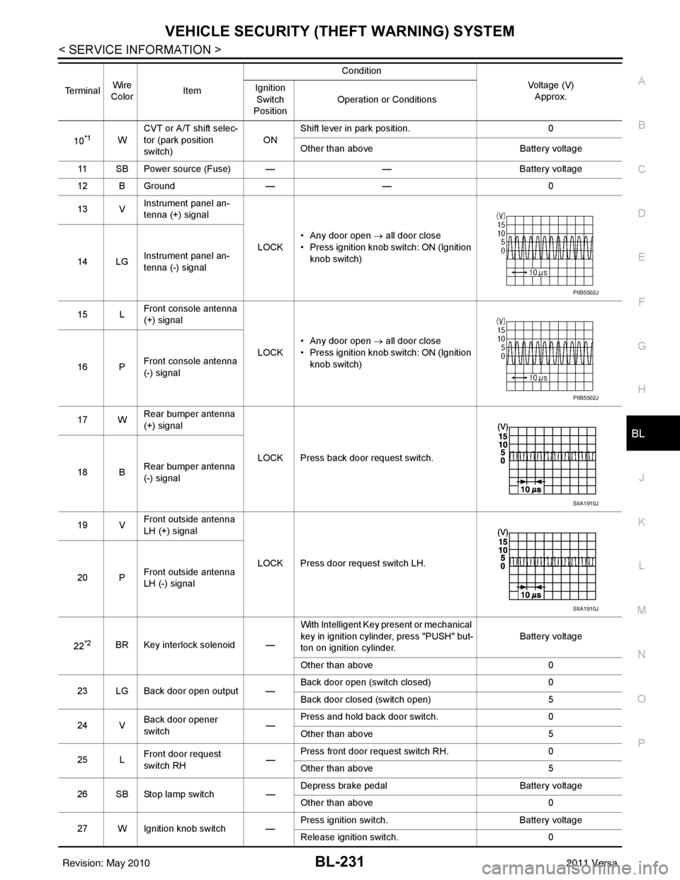
VEHICLE SECURITY (THEFT WARNING) SYSTEMBL-231
< SERVICE INFORMATION >
C
DE
F
G H
J
K L
M A
B
BL
N
O P
10*1W CVT or A/T shift selec-
tor (park position
switch)
ONShift lever in park position.
0
Other than above Battery voltage
11 SB Power source (Fus e) — —Battery voltage
12 B Ground —— 0
13 V Instrument panel an-
tenna (+) signal
LOCK• Any door open
→ all door close
• Press ignition knob switch: ON (Ignition knob switch)
14 LG Instrument panel an-
tenna (-) signal
15 L Front console antenna
(+) signal
LOCK• Any door open
→ all door close
• Press ignition knob switch: ON (Ignition knob switch)
16 P Front console antenna
(-) signal
17 W Rear bumper antenna
(+) signal
LOCK Press back door request switch.
18 B Rear bumper antenna
(-) signal
19 V Front outside antenna
LH (+) signal
LOCK Press door request switch LH.
20 P Front outside antenna
LH (-) signal
22
*2BR Key interlock solenoid — With Intelligent Key present or mechanical
key in ignition cylinder, press "PUSH" but-
ton on ignition cylinder.
Battery voltage
Other than above 0
23 LG Back door open output — Back door open (switch closed)
0
Back door closed (switch open) 5
24 V Back door opener
switch —Press and hold back door switch.
0
Other than above 5
25 L Front door request
switch RH
—Press front door request switch RH.
0
Other than above 5
26 SB Stop lamp switch —Depress brake pedal
Battery voltage
Other than above 0
27 W Ignition knob switch — Press ignition switch.
Battery voltage
Release ignition switch. 0
Terminal
Wire
Color Item Condition
Voltage (V)Approx.
Ignition
Switch
Position Operation or Conditions
PIIB5502J
PIIB5502J
SIIA1910J
SIIA1910J
Revision: May 2010
2011 Versa