2011 NISSAN TIIDA Electrical diagr
[x] Cancel search: Electrical diagrPage 2101 of 3787
![NISSAN TIIDA 2011 Service Repair Manual DTC P0420 THREE WAY CATALYST FUNCTIONEC-807
< SERVICE INFORMATION > [MR18DE]
C
D
E
F
G H
I
J
K L
M A
EC
NP
O
OK or NG
OK >> GO TO 5.
NG >> Follow the
EC-574, "
Basic Inspection".
5.CHECK FUEL INJECTO NISSAN TIIDA 2011 Service Repair Manual DTC P0420 THREE WAY CATALYST FUNCTIONEC-807
< SERVICE INFORMATION > [MR18DE]
C
D
E
F
G H
I
J
K L
M A
EC
NP
O
OK or NG
OK >> GO TO 5.
NG >> Follow the
EC-574, "
Basic Inspection".
5.CHECK FUEL INJECTO](/manual-img/5/57396/w960_57396-2100.png)
DTC P0420 THREE WAY CATALYST FUNCTIONEC-807
< SERVICE INFORMATION > [MR18DE]
C
D
E
F
G H
I
J
K L
M A
EC
NP
O
OK or NG
OK >> GO TO 5.
NG >> Follow the
EC-574, "
Basic Inspection".
5.CHECK FUEL INJECTOR
1. Stop engine and turn ignition switch OFF.
2. Disconnect ECM harness connector.
3. Turn ignition switch ON.
4. Check voltage between ECM terminals 25, 29, 30, 31 and ground with CONSULT-III or tester. Refer to Wiring Diagram for fuel injectors, EC-1010, "
Wiring Diagram".
OK or NG
OK >> GO TO 6.
NG >> Perform EC-1011, "
Diagnosis Procedure".
6.CHECK FUNCTION OF IGNITION COIL-I
CAUTION:
Do the following procedure in the place where ventilation is good without the combustible.
1. Turn ignition switch OFF.
2. Remove fuel pump (1) fuse in IPDM E/R (2) to release fuel pres- sure.
NOTE:
Do not use CONSULT-III to release fuel pressure, or fuel pres-
sure applies again during the following procedure.
- : Vehicle front
3. Start engine.
4. After engine stalls, crank it two or three times to release all fuel pressure.
5. Turn ignition switch OFF.
6. Remove all ignition coil harness connectors to avoid the electri- cal discharge from the ignition coils.
7. Remove ignition coil and spark plug of the cylinder to be checked.
8. Crank engine for 5 seconds or more to remove combustion gas in the cylinder.
9. Connect spark plug and harness connector to ignition coil.
10. Fix ignition coil using a rope etc. with gap of 13 - 17 mm (0.52 - 0.66 in) between the edge of the spark plug and grounded metal
portion as shown in the figure.
11. Crank engine for about 3 seconds, and check whether spark is
generated between the spark plug and the grounded metal por-
tion.
CAUTION:
• Do not approach to the spark plug and the ignition coilwithin 50 cm. Be careful not to get an electrical shock
while checking, because the el ectrical discharge voltage
becomes 20 kV or more.
Items Specifications
Target idle speed A/T: 700 ±
50 rpm (in P or N position)
CVT: 700 ± 50 rpm (in P or N position)
M/T: 700 ± 50 rpm (in Neutral position)
Ignition timing A/T: 13 ±
5° BTDC (in P or N position)
CVT: 13 ± 5 ° BTDC (in P or N position)
M/T: 13 ± 5 ° BTDC (in Neutral position)
Voltage: Battery voltage
Spark should be generated.
PBIB2958E
PBIB2325E
Revision: May 2010 2011 Versa
Page 2705 of 3787

GI-1
GENERAL INFORMATION
C
DE
F
G H
I
J
K L
M B
GI
SECTION GI
N
O P
CONTENTS
GENERAL INFORMATION
SERVICE INFORMATION .. ..........................2
PRECAUTIONS .............................................. .....2
Description .......................................................... ......2
Precaution for Supplemental Restraint System
(SRS) "AIR BAG" and "SEAT BELT PRE-TEN-
SIONER" ...................................................................
2
Precaution Necessary for Steering Wheel Rota-
tion After Battery Disconnect ............................... ......
2
General Precaution ...................................................3
Precaution for Three Way Catalyst ...........................4
Precaution for Fuel (Unleaded Regular Gasoline
Recommended) .........................................................
4
Precaution for Multiport Fuel Injection System or
Engine Control System .............................................
5
Precaution for Hoses .................................................5
Precaution for Engine Oils ........................................6
Precaution for Air Conditioning .................................6
HOW TO USE THIS MANUAL ............................7
Description .......................................................... ......7
Terms ........................................................................7
Units ..........................................................................7
Contents ....................................................................7
Relation between Illustrations and Descriptions .......8
Component ................................................................8
How to Follow Trouble Diagnosis ..............................9
How to Read Wiring Diagram ..................................13
Abbreviations ...................................................... ....20
SERVICE INFORMATION FOR ELECTRICAL
INCIDENT ...........................................................
22
How to Check Terminal ...........................................22
How to Perform Efficient Diagnosis for an Electri-
cal Incident .......................................................... ....
25
Control Units and Electrical Parts ............................32
CONSULT-III CHECKING SYSTEM .................35
Description ...............................................................35
Function and System Application ............................35
CONSULT-III Data Link Connector (DLC) Circuit ....36
LIFTING POINT .................................................38
Special Service Tool ................................................38
Garage Jack and Safety Stand and 2-Pole Lift .......38
Board-On Lift ...........................................................39
TOW TRUCK TOWING .....................................40
Tow Truck Towing ...................................................40
Vehicle Recovery (Freeing a Stuck Vehicle) ...........40
TIGHTENING TORQUE OF STANDARD
BOLTS ...............................................................
41
Tightening Torque Table .........................................41
RECOMMENDED CHEMICAL PRODUCTS
AND SEALANTS ...............................................
42
Recommended Chemical Product and Sealant .......42
IDENTIFICATION INFORMATION ....................43
Model Variation ........................................................43
Dimensions ..............................................................46
Wheels & Tires ........................................................46
TERMINOLOGY ................................................47
SAE J1930 Terminology List ...................................47
Revision: May 2010 2011 Versa
Page 2714 of 3787
GI-10
< SERVICE INFORMATION >
HOW TO USE THIS MANUAL
3.Refer to Component Parts and Harness Connector Location for the Systems described in each
section for identifi cation/location of componen ts and harness connectors.
4. Refer to the Circuit Diagram for quick pinpoint check.
If you need to check circuit continuity between harness connectors in more detail, such as when a
sub-harness is used, refer to Wiring Diagram in each individual section and Harness Layout in PG
section for identificatio n of harness connectors.
5. When checking circuit continuity, ignition switch should be OFF.
6. Before checking voltage at co nnectors, check battery voltage.
7. After accomplishing the Diagnostic Procedures an d Electrical Components Inspection, make sure
that all harness connectors ar e reconnected as they were.
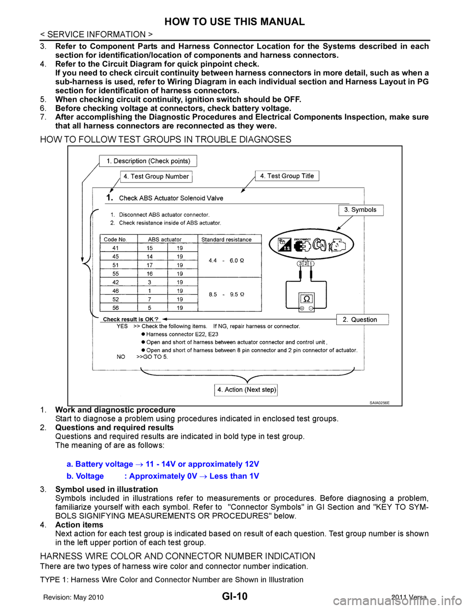
HOW TO FOLLOW TEST GROUPS IN TROUBLE DIAGNOSES
1.Work and diagnostic procedure
Start to diagnose a problem using procedures indicated in enclosed test groups.
2. Questions and required results
Questions and required results are indicated in bold type in test group.
The meaning of are as follows:
3. Symbol used in illustration
Symbols included in illustrations refer to measurements or procedures. Before diagnosing a problem,
familiarize yourself with each symbol. Refer to "Connector Symbols" in GI Section and "KEY TO SYM-
BOLS SIGNIFYING MEASUREME NTS OR PROCEDURES" below.
4. Action items
Next action for each test group is indicated based on result of each question. Test group number is shown
in the left upper portion of each test group.
HARNESS WIRE COLOR AND CONNECTOR NUMBER INDICATION
There are two types of harness wire color and connector number indication.
TYPE 1: Harness Wire Color and Connector Number are Shown in Illustration
SAIA0256E
a. Battery voltage → 11 - 14V or approximately 12V
b. Voltage : Approximately 0V → Less than 1V
Revision: May 2010 2011 Versa
Page 2724 of 3787
GI-20
< SERVICE INFORMATION >
HOW TO USE THIS MANUAL
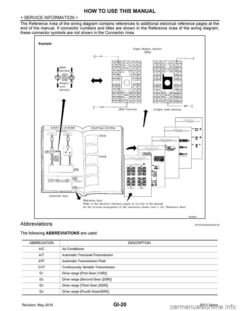
The Reference Area of the wiring diagram contains references to additional electrical reference pages at the
end of the manual. If connector numbers and titles are shown in the Reference Area of the wiring diagram,
these connector symbols are not shown in the Connector Area.
AbbreviationsINFOID:0000000005929726
The following ABBREVIATIONS are used:
SGI092A
ABBREVIATION DESCRIPTION
A/C Air Conditioner
A/T Automatic Transaxle/Transmission
ATF Automatic Transmission Fluid
CVT Continuously Variable Transmission
D
1Drive range [First Gear (1GR)]
D
2Drive range [Second Gear (2GR)]
D
3Drive range [Third Gear (3GR)]
D
4Drive range [Fourth Gear(4GR)]
Revision: May 2010 2011 Versa
Page 2730 of 3787
GI-26
< SERVICE INFORMATION >
SERVICE INFORMATION FOR ELECTRICAL INCIDENT
• Cold or hot start up
Get a thorough description of the incident from the customer. It is important for simulating the conditions of the
problem.
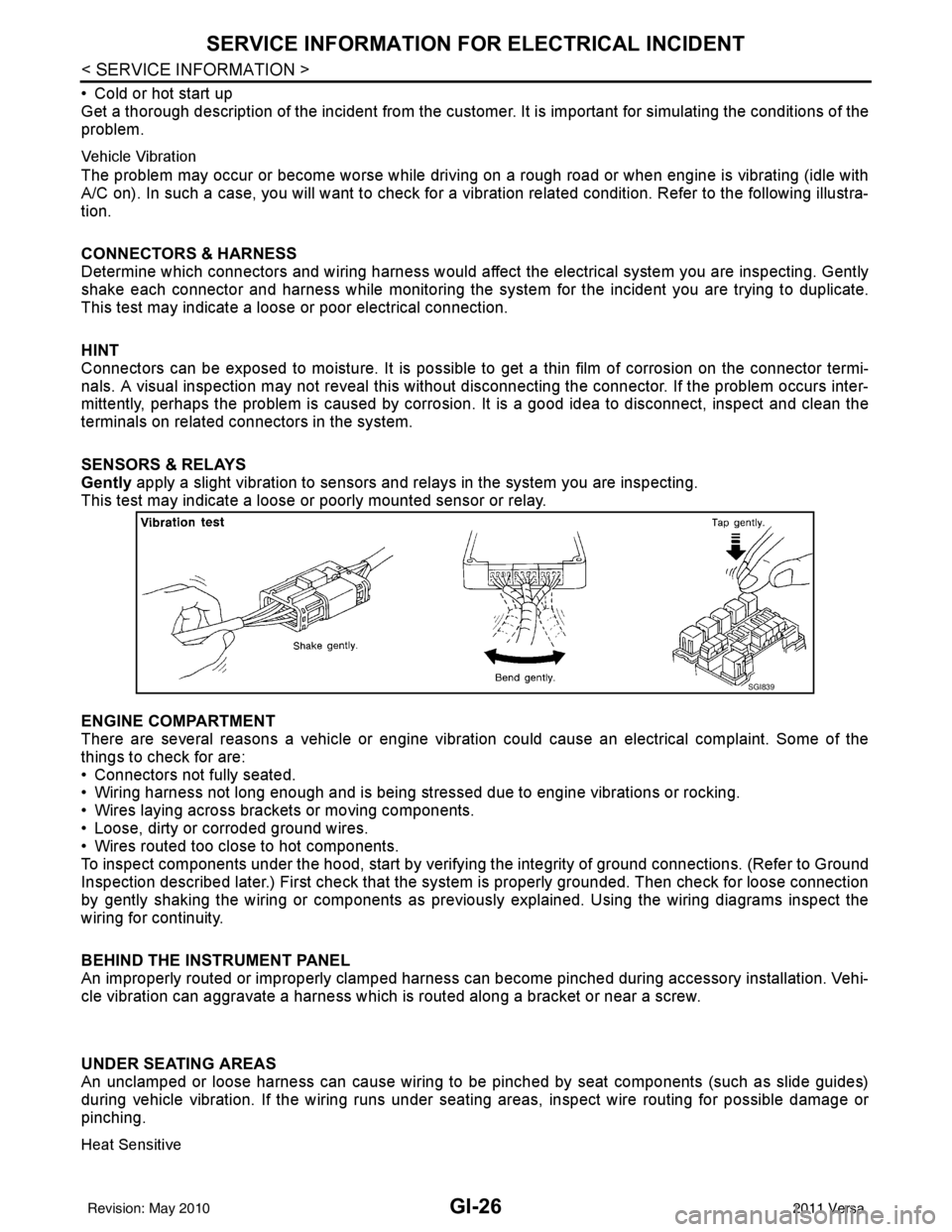
Vehicle Vibration
The problem may occur or become worse while driving on a rough road or when engine is vibrating (idle with
A/C on). In such a case, you will want to check for a vibration related condition. Refer to the following illustra-
tion.
CONNECTORS & HARNESS
Determine which connectors and wiring harness would affect the electrical system you are inspecting. Gently
shake each connector and harness while monitoring the sy stem for the incident you are trying to duplicate.
This test may indicate a loose or poor electrical connection.
HINT
Connectors can be exposed to moisture. It is possible to get a thin film of corrosion on the connector termi-
nals. A visual inspection may not reveal this without disconnecting the connector. If the problem occurs inter-
mittently, perhaps the problem is caused by corrosion. It is a good idea to disconnect, inspect and clean the
terminals on related connectors in the system.
SENSORS & RELAYS
Gently apply a slight vibration to sensors and relays in the system you are inspecting.
This test may indicate a loose or poorly mounted sensor or relay.
ENGINE COMPARTMENT
There are several reasons a vehicle or engine vibration could cause an e\
lectrical complaint. Some of the
things to check for are:
• Connectors not fully seated.
• Wiring harness not long enough and is being stressed due to engine vibrations or rocking.
• Wires laying across brackets or moving components.
• Loose, dirty or corroded ground wires.
• Wires routed too close to hot components.
To inspect components under the hood, start by verifyi ng the integrity of ground connections. (Refer to Ground
Inspection described later.) First check that the system is properly grounded. Then check for loose connection
by gently shaking the wiring or components as previous ly explained. Using the wiring diagrams inspect the
wiring for continuity.
BEHIND THE INSTRUMENT PANEL
An improperly routed or improperly clamped harness can become pinched during accessory installation. Vehi-
cle vibration can aggravate a harness which is routed along a bracket or near a screw.
UNDER SEATING AREAS
An unclamped or loose harness can cause wiring to be pinched by seat components (such as slide guides)
during vehicle vibration. If the wiring runs under s eating areas, inspect wire routing for possible damage or
pinching.
Heat Sensitive
SGI839
Revision: May 2010 2011 Versa
Page 2847 of 3787
LAN-1
ELECTRICAL
C
DE
F
G H
I
J
L
M
SECTION LAN
A
B
LAN
N
O P
CONTENTS
LAN SYSTEM
CAN FUNDAMENTAL
SERVICE INFORMATION .. ..........................
6
PRECAUTIONS .............................................. .....6
Precautions for Trouble Diagnosis ...................... ......6
Precautions for Harness Repair ................................6
CAN COMMUNICATION SYSTEM ................ .....7
System Description ............................................. ......7
System Diagram ........................................................7
CAN Communication Control Circuit .........................8
DIAG ON CAN .....................................................9
Description .......................................................... ......9
System Diagram ........................................................9
TROUBLE DIAGNOSIS .....................................10
Condition of Error Detection ................................ ....10
Symptom When Error Occurs in CAN Communi-
cation System ...................................................... ....
10
CAN Diagnosis with CONSULT-III ..........................13
Self-Diagnosis .........................................................14
CAN Diagnostic Support Monitor ............................14
How to Use CAN Communication Signal Chart ......16
DIAGNOSIS AND REPAIR WORKFLOW .........17
Trouble Diagnosis Flow Chart ............................. ....17
Trouble Diagnosis Procedure ..................................17
CAN
SERVICE INFORMATION .. .........................
22
HOW TO USE THIS SECTION ....................... ....22
Caution ................................................................ ....22
Abbreviation List ......................................................22
PRECAUTIONS ..................................................23
Precaution for Supplemental Restraint System
(SRS) "AIR BAG" and "SEAT BELT PRE-TEN-
SIONER" ............................................................. ....
23
Precautions for Trouble Diagnosis ..........................23
Precautions for Harness Repair .......................... ....23
DIAGNOSIS AND REPAIR WORKFLOW ........25
Interview Sheet ........................................................25
CAN COMMUNICATION SYSTEM ...................26
CAN System Specification Chart .............................26
CAN Communication Signal Chart ..........................27
CAN COMMUNICATION SYSTEM ...................29
Component Parts Location ......................................29
Schematic ................................................................30
Wiring Diagram - CAN - ...........................................31
MALFUNCTION AREA CHART ........................33
Main Line .................................................................33
Branch Line .............................................................33
Short Circuit .............................................................33
MAIN LINE BETWEEN DLC AND ABS CIR-
CUIT ..................................................................
34
Diagnosis Procedure ...............................................34
MAIN LINE BETWEEN DLC AND TCM CIR-
CUIT ..................................................................
35
Diagnosis Procedure ...............................................35
ECM BRANCH LINE CIRCUIT .........................36
Diagnosis Procedure ...............................................36
BCM BRANCH LINE CIRCUIT .........................37
Diagnosis Procedure ...............................................37
DLC BRANCH LINE CIRCUIT ..........................38
Diagnosis Procedure ...............................................38
EPS BRANCH LINE CIRCUIT ..........................39
Diagnosis Procedure ...............................................39
I-KEY BRANCH LINE CIRCUIT ........................40
Diagnosis Procedure ...............................................40
M&A BRANCH LINE CIRCUIT .........................41
Revision: May 2010 2011 Versa
Page 3033 of 3787
LT-1
ELECTRICAL
C
DE
F
G H
I
J
L
M
SECTION LT
A
B
LT
N
O P
CONTENTS
LIGHTING SYSTEM
SERVICE INFORMATION .. ..........................3
PRECAUTIONS .............................................. .....3
Precaution for Supplemental Restraint System
(SRS) "AIR BAG" and "SEAT BELT PRE-TEN-
SIONER" ............................................................. ......
3
Precaution Necessary for Steering Wheel Rota-
tion After Battery Disconnect ............................... ......
3
HEADLAMP (FOR USA) .....................................5
Component Parts and Harness Connector Loca-
tion ...................................................................... ......
5
System Description ...................................................5
CAN COMMUNICATION SYSTEM DESCRIP-
TION .................................................................... ......
6
Schematic .................................................................7
Wiring Diagram .........................................................8
Terminal and Reference Value for BCM .................11
Terminal and Reference Value for IPDM E/R .........11
How to Perform Trouble Diagnosis .........................12
Preliminary Check ...................................................12
CONSULT-III Function (BCM) .................................12
CONSULT-III Function (IPDM E/R) .........................13
Headlamp High Beam Does Not Illuminate (Both
Sides) .................................................................. ....
15
Headlamp High Beam Does Not Illuminate (One
Side) .................................................................... ....
17
High Beam Indicator Lamp Does Not Illuminate .....18
Headlamp Low Beam Does Not Illuminate (Both
Sides) .................................................................. ....
19
Headlamp Low Beam Does Not Illuminate (One
Side) .................................................................... ....
21
Headlamps Do Not Turn OFF .................................22
Aiming Adjustment ..................................................23
Bulb Replacement ...................................................24
Removal and Installation .........................................25
Disassembly and Assembly ................................ ....25
HEADLAMP (FOR CANADA) - DAYTIME
LIGHT SYSTEM - ........................................... ....
27
Component Parts and Harness Connector Loca-
tion ....................................................................... ....
27
System Description ..................................................27
CAN Communication System Description ...............29
Schematic ................................................................30
Wiring Diagram - DTRL - .........................................31
Terminal and Reference Value for BCM ..................34
Terminal and Reference Value for IPDM E/R ...... ....34
How to Perform Trouble Diagnosis ..........................35
Preliminary Check ...................................................35
CONSULT-III Function (BCM) .................................35
CONSULT-III Function (IPDM E/R) ..................... ....35
Daytime Light Control Does Not Operate Properly
(High Beam Headlamps Operate Properly) .............
35
Aiming Adjustment ...................................................37
Bulb Replacement ...................................................38
Removal and Installation .........................................39
Disassembly and Assembly .....................................39
FRONT FOG LAMP ..........................................41
Component Parts and Harness Connector Loca-
tion ...........................................................................
41
System Description ..................................................41
CAN Communication System Description ...............42
Wiring Diagram - F/FOG - .......................................43
Terminal and Reference Value for BCM ..................44
Terminal and Reference Value for IPDM E/R ...... ....44
How to Proceed with Trouble Diagnosis ..................45
Preliminary Check ............................................... ....45
CONSULT-III Function (BCM) .................................45
CONSULT-III Function (IPDM E/R) ..................... ....45
Front Fog lamps Do Not Illuminate (Both Sides) .....45
Front Fog Lamp Does Not Illuminate (One Side) ....47
Aiming Adjustment ...................................................48
Bulb Replacement ...................................................49
Removal and Installation .........................................49
TURN SIGNAL AND HAZARD WARNING
LAMPS ..............................................................
50
Component Parts and Harness Connector Loca-
tion ...........................................................................
50
Revision: May 2010 2011 Versa
Page 3421 of 3787
PG-1
ELECTRICAL
C
DE
F
G H
I
J
L
M
SECTION PG
A
B
PG
N
O P
CONTENTS
POWER SUPPLY, GROUND & CIRCUIT ELEMENTS
SERVICE INFORMATION .. ..........................2
PRECAUTIONS .............................................. .....2
Precaution for Supplemental Restraint System
(SRS) "AIR BAG" and "SEAT BELT PRE-TEN-
SIONER" ............................................................. ......
2
Precaution Necessary for Steering Wheel Rota-
tion After Battery Disconnect ............................... ......
2
POWER SUPPLY ROUTING CIRCUIT ...............4
Schematic ........................................................... ......4
Wiring Diagram - POWER - ......................................6
Fuse ........................................................................16
Fusible Link .............................................................16
Circuit Breaker (Built Into BCM) ..............................16
Circuit Breaker ........................................................16
IPDM E/R (INTELLIGENT POWER DISTRI-
BUTION MODULE ENGINE ROOM) .................
17
System Description ............................................. ....17
CAN Communication System Description ...............18
Function of Detecting Ignition Relay Malfunction ....18
CONSULT-III Function (IPDM E/R) ..................... ....18
Auto Active Test ......................................................20
IPDM E/R Terminal Arrangement - Type A .............23
IPDM E/R Terminal Arrangement - Type B .............24
Terminal and Reference Value for IPDM E/R .........25
IPDM E/R Power/Ground Circuit Inspection ...........27
Inspection with CONSULT-III (Self-Diagnosis) .......28
Removal and Installation of IPDM E/R ................ ....28
GROUND CIRCUIT ...........................................30
Ground Distribution .............................................. ....30
HARNESS .........................................................39
Harness Layout ................................................... ....39
Wiring Diagram Codes (Cell Codes) .......................58
ELECTRICAL UNITS LOCATION ....................61
Electrical Units Location ..........................................61
HARNESS CONNECTOR .................................65
Description ...............................................................65
ELECTRICAL UNITS ........................................68
Terminal Arrangement .............................................68
STANDARDIZED RELAY .................................69
Description ...............................................................69
SUPER MULTIPLE JUNCTION (SMJ) .............71
Terminal Arrangement .............................................71
FUSE BLOCK-JUNCTION BOX (J/B) ..............73
Terminal Arrangement .............................................73
FUSE AND FUSIBLE LINK BOX ......................74
Terminal Arrangement .............................................74
Revision: May 2010 2011 Versa