2011 NISSAN TIIDA Clock
[x] Cancel search: ClockPage 463 of 3787
![NISSAN TIIDA 2011 Service Repair Manual AV-66
< SERVICE INFORMATION >[AUDIO WITH NAVIGATION]
AUDIO
END ON-BOARD DIAGNOSIS
Turn OFF ignition switch.
Noise InspectionINFOID:0000000005931317
The vehicle itself can be a source of noise if noise](/manual-img/5/57396/w960_57396-462.png "NISSAN TIIDA 2011 Service Repair Manual AV-66
< SERVICE INFORMATION >[AUDIO WITH NAVIGATION]
AUDIO
END ON-BOARD DIAGNOSIS
Turn OFF ignition switch.
Noise InspectionINFOID:0000000005931317
The vehicle itself can be a source of noise if noise")
AV-66
< SERVICE INFORMATION >[AUDIO WITH NAVIGATION]
AUDIO
END ON-BOARD DIAGNOSIS
Turn OFF ignition switch.
Noise InspectionINFOID:0000000005931317
The vehicle itself can be a source of noise if noise
prevention parts or electrical equipment is malfunctioning.
Check if noise is caused and/or changed by engine speed, ignition switch turned to each position, and opera-
tion of each piece of electrical equipment, and determine the cause.
NOTE:
The source of the noise can be found easily by listening to the noise while removing the fuses of electrical
components, one by one.
TYPE OF NOISE AND POSSIBLE CAUSE
Symptom ChartINFOID:0000000006216708
MALFUNCTION WITH NAVIGATION
System configuration • 8 pulses speed
• Clock ON/OFF
• Equalizer setup X11C
• RF tuning
• Antenna type
• Sound system
• Sub Out: Code
• Steering wheel The device is configured by a connect-
ed hardware circuit.
The parameter is
influenced.
Self test •Bluetooth
® module Access Mal-
function
• SD-card Access Malfunction
• Radio-Antenna Circuit Malfunc-
tion
• GPS Antenna Circuit Malfunc-
tion
• Microphone Circuit Malfunction A system self test is executed: the re-
sult is stored into
the error memory
which is shown afterwards as a list of
codes of the detected malfunctions.
Mode
ItemContent
Occurrence condition Possible cause
Occurs only when engine is ON. A continuous growling noise occurs. The speed of
the noise varies with changes in the engine speed.
Ignition components
A whistling noise occurs while the engine speed is
high. A booming noise occurs while the engine is
running and the lighting switch is ON. Generator
Noise only occurs when various
electrical components are oper-
ating. A cracking or snapping sound occurs with the op-
eration of various switches.
Relay malfunction, radio malfunction
The noise occurs when various motors are operat-
ing. • Motor case ground
• Motor
The noise occurs constantly, not just under certain conditions. • Rear defogger coil malfunction
• Open circuit in printed heater
A cracking or snapping sound occurs while the vehicle is being driven, especially when
it is vibrating excessively. • Ground wire of body parts.
• Ground due to improper part installation
• Wiring connections or a short circuit
Symptoms
Check itemsProbable malfunction location / Action to
take
Display does not turn ON. All switches cannot be operated.
AV control unit power supply and ground
circuit. Refer to
AV- 6 9
.
All switches can be operated. AV control unit. Refer to AV- 6 9
.
Revision: May 2010 2011 Versa
Page 517 of 3787
SQUEAK AND RATTLE TROUBLE DIAGNOSESBL-7
< SERVICE INFORMATION >
C
DE
F
G H
J
K L
M A
B
BL
N
O P
SQUEAK AND RATTLE TROUBLE DIAGNOSES
Work FlowINFOID:0000000005929273
CUSTOMER INTERVIEW
Interview the customer if possible, to determine the conditions that exist when the noise occurs. Use the Diag-
nostic Worksheet during the interv iew to document the facts and conditions when the noise occurs and any
customer's comments; refer to BL-11, "
Diagnostic Worksheet". This information is necessary to duplicate the
conditions that exist when the noise occurs.
• The customer may not be able to provide a detailed descr iption or the location of the noise. Attempt to obtain
all the facts and conditions that exist when the noise occurs (or does not occur).
• If there is more than one noise in the vehicle, be sure to diagnose and repair the noise that the customer is
concerned about. This can be accomplished by test driving the vehicle with the customer.
• After identifying the type of noise, isolate the noise in terms of its characteristics. The noise characteristics
are provided so the customer, service adviser and technician are all speaking the same language when
defining the noise.
• Squeak —(Like tennis shoes on a clean floor)
Squeak characteristics include the light contact/fast movement/brought on by road conditions/hard surfaces
= higher pitch noise/softer surfaces = lower pitch noises/edge to surface = chirping.
• Creak—(Like walking on an old wooden floor)
Creak characteristics include firm contact/slow mo vement/twisting with a rotational movement/pitch depen-
dent on materials/often brought on by activity.
• Rattle—(Like shaking a baby rattle)
Rattle characteristics include the fast repeated contac t/vibration or similar movement/loose parts/missing
clip or fastener/incorrect clearance.
• Knock —(Like a knock on a door)
Knock characteristics include hollow sounding/someti mes repeating/often brought on by driver action.
• Tick—(Like a clock second hand) Tick characteristics include gentle contacting of li ght materials/loose components/can be caused by driver
action or road conditions.
• Thump—(Heavy, muffled knock noise) Thump characteristics include softer k nock/dead sound often brought on by activity.
• Buzz—(Like a bumble bee)
Buzz characteristics include high frequency rattle/firm contact.
• Often the degree of acceptable noise level will vary depending upon the person. A noise that you may judge as acceptable may be very irritating to the customer.
• Weather conditions, especially humidity and temperature, may have a great effect on noise level.
DUPLICATE THE NOISE AND TEST DRIVE
If possible, drive the vehicle with the customer until the noise is duplicated. Note any additional information on
the Diagnostic Worksheet regarding the conditions or lo cation of the noise. This information can be used to
duplicate the same conditions when you confirm the repair.
SBT842
Revision: May 2010 2011 Versa
Page 854 of 3787
BRAKE PEDALBR-7
< SERVICE INFORMATION >
C
DE
G H
I
J
K L
M A
B
BR
N
O P
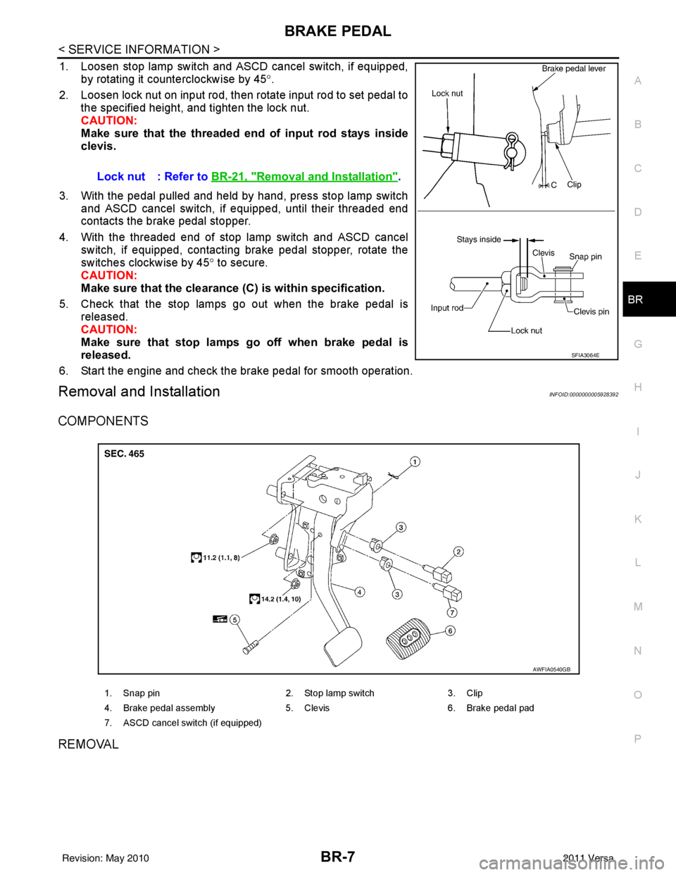
1. Loosen stop lamp switch and ASCD cancel switch, if equipped, by rotating it counterclockwise by 45 °.
2. Loosen lock nut on input rod, then rotate input rod to set pedal to the specified height, and tighten the lock nut.
CAUTION:
Make sure that the threaded end of input rod stays inside
clevis.
3. With the pedal pulled and held by hand, press stop lamp switch and ASCD cancel switch, if equipped, until their threaded end
contacts the brake pedal stopper.
4. With the threaded end of stop lamp switch and ASCD cancel switch, if equipped, contacting brake pedal stopper, rotate the
switches clockwise by 45 ° to secure.
CAUTION:
Make sure that the clearance (C) is within specification.
5. Check that the stop lamps go out when the brake pedal is released.
CAUTION:
Make sure that stop lamps go off when brake pedal is
released.
6. Start the engine and check the brake pedal for smooth operation.
Removal and InstallationINFOID:0000000005928392
COMPONENTS
REMOVAL
Lock nut : Refer to BR-21, "Removal and Installation".
SFIA3064E
1. Snap pin 2. Stop lamp switch3. Clip
4. Brake pedal assembly 5. Clevis6. Brake pedal pad
7. ASCD cancel switch (if equipped)
AWFIA0540GB
Revision: May 2010 2011 Versa
Page 859 of 3787
BR-12
< SERVICE INFORMATION >
BRAKE TUBE AND HOSE
• All tubes and hoses must be free from excessive bending, twisting and pulling.
• Make sure there is no interference with other part s when turning steering both clockwise and coun-
terclockwise.
• Brake tubes and hoses are an important safety part. Always disassemble the parts and retighten
their fittings, if a brake fluid leak is detected. Replace applicable part with a new one, if damaged part
is detected.
• Be careful not to splash brake fluid on painted areas; it may cause paint damage. If brake fluid is
splashed on painted surfaces of body , immediately wipe them with cloth and then wash it away with
water.
• Do not bend or twist brake hose sharply, or strongly pull it.
• When removing components, cover brake line connect ions so that dirt, dust, or other foreign mat-
ters do not get in.
• Refill using recommended brake fluid. Refer to MA-14, "
Fluids and Lubricants".
• Never reuse drained brake fluid.
Front Brake Tube and HoseINFOID:0000000005928397
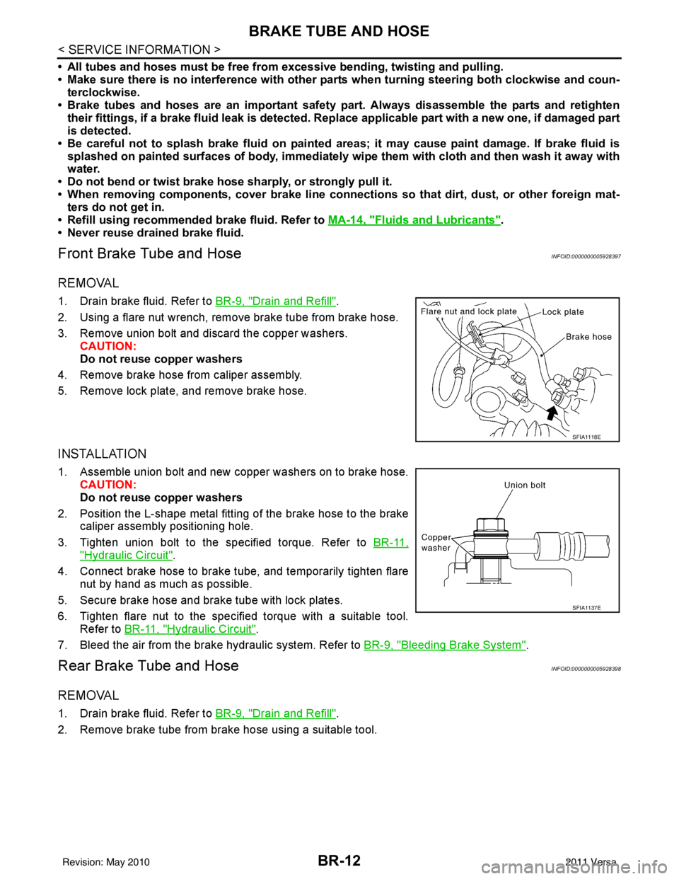
REMOVAL
1. Drain brake fluid. Refer to BR-9, "Drain and Refill".
2. Using a flare nut wrench, remove brake tube from brake hose.
3. Remove union bolt and discard the copper washers. CAUTION:
Do not reuse copper washers
4. Remove brake hose from caliper assembly.
5. Remove lock plate, and remove brake hose.
INSTALLATION
1. Assemble union bolt and new copper washers on to brake hose. CAUTION:
Do not reuse copper washers
2. Position the L-shape metal fitting of the brake hose to the brake caliper assembly positioning hole.
3. Tighten union bolt to the specified torque. Refer to BR-11,
"Hydraulic Circuit".
4. Connect brake hose to brake tube, and temporarily tighten flare nut by hand as much as possible.
5. Secure brake hose and brake tube with lock plates.
6. Tighten flare nut to the specified torque with a suitable tool. Refer to BR-11, "
Hydraulic Circuit".
7. Bleed the air from the brake hydraulic system. Refer to BR-9, "
Bleeding Brake System".
Rear Brake Tube and HoseINFOID:0000000005928398
REMOVAL
1. Drain brake fluid. Refer to BR-9, "Drain and Refill".
2. Remove brake tube from brake hose using a suitable tool.
SFIA1118E
SFIA1137E
Revision: May 2010 2011 Versa
Page 992 of 3787
CLUTCH MASTER CYLINDERCL-11
< SERVICE INFORMATION >
DE
F
G H
I
J
K L
M A
B
CL
N
O P
CLUTCH MASTER CYLINDER
Removal and InstallationINFOID:0000000005928997
REMOVAL
1. Remove the battery, battery tray and brackets. Refer to SC-5.
2. Remove the air cleaner and air duct. Refer to EM-25, "
Removal and Installation" (HR16DE models), EM-
135, "Removal and Installation" (MR18DE models).
3. Use one of the following methods to remove hose from master cylinder.
• Drain clutch fluid from reservoir tank and remove hose.
• Remove hose from master cylinder. Immediately plug hose and reservoir tank to prevent clutch fluid
from dripping.
CAUTION:
Do not spill clutch fluid onto painted surfaces. If it spills, wipe up immediately and wash the
affected area with water.
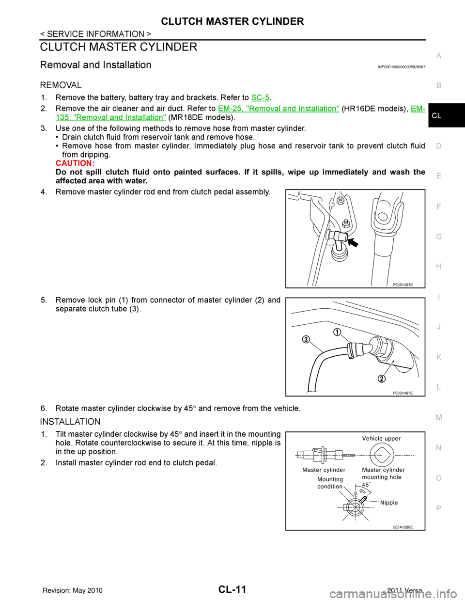
4. Remove master cylinder rod end from clutch pedal assembly.
5. Remove lock pin (1) from connector of master cylinder (2) and separate clutch tube (3).
6. Rotate master cylinder clockwise by 45 ° and remove from the vehicle.
INSTALLATION
1. Tilt master cylinder clockwise by 45° and insert it in the mounting
hole. Rotate counterclockwise to secure it. At this time, nipple is
in the up position.
2. Install master cylinder rod end to clutch pedal.
PCIB1491E
PCIB1497E
SCIA1286E
Revision: May 2010 2011 Versa
Page 1064 of 3787
![NISSAN TIIDA 2011 Service Repair Manual PRECAUTIONSCVT-9
< SERVICE INFORMATION > [RE0F08B]
D
E
F
G H
I
J
K L
M A
B
CVT
N
O P
6. Turn ignition switch ON. CAUTION:
Never start engine.
7. Select “Self Diagnostic Results” in “TRANSMISSION](/manual-img/5/57396/w960_57396-1063.png "NISSAN TIIDA 2011 Service Repair Manual PRECAUTIONSCVT-9
< SERVICE INFORMATION > [RE0F08B]
D
E
F
G H
I
J
K L
M A
B
CVT
N
O P
6. Turn ignition switch ON. CAUTION:
Never start engine.
7. Select “Self Diagnostic Results” in “TRANSMISSION")
PRECAUTIONSCVT-9
< SERVICE INFORMATION > [RE0F08B]
D
E
F
G H
I
J
K L
M A
B
CVT
N
O P
6. Turn ignition switch ON. CAUTION:
Never start engine.
7. Select “Self Diagnostic Results” in “TRANSMISSION”.
8. Shift the selector lever to “R” position.
9. Depress slightly the accelerator pedal (Pedal angle: 2/8) while depressing the brake pedal.
10. Select “Erase” with step 9.
11. Release brake pedal and accelerator pedal.
12. Turn ignition switch OFF while keeping the selector lever in “R” position.
13. Wait approximately 10 seconds.
14. Turn ignition switch ON while keeping the selector lever in “R” position.
15. Select “Special function” in “TRANSMISSION”.
16. Check that the value on “CALIB DATA” in CONSULT-II I is the same as the data listed in the table below.
• Restart the procedure from step 3 if the values are not the same.
CALIB DATA
17. Shift the selector lever to “P” position.
18. Check that the shift position indicator in combinat ion meter turns ON. (It indicates approximately 1 or 2
seconds after shifting the selector lever to “P” position.)
• Check the following items if shift position indicator does not turn ON. Repair or replace accordingly as
necessary.
- The harness between TCM and ROM ASSY in transaxle assembly is open or shorted.
- Terminals disconnected, loose, or bent from connector housing.
- Power supply and ground of TCM. Refer to CVT-113, "
Description".
PATTERN C
1. Replace transaxle assembly first, and then replace TCM.
2. Perform the service of “PATTERN A”.
(Perform the service of “PATTERN B” if TCM is replaced first.)
Removal and Installation Procedure for CVT Unit ConnectorINFOID:0000000005928724
REMOVAL
Rotate bayonet ring counterclockwise, pull out CVT unit harness
connector upward and disconnect it.
INSTALLATION
Item name Display value
UNIT CLB ID 1 00
UNIT CLB ID 2 00
UNIT CLB ID 3 00
UNIT CLB ID 4 00
UNIT CLB ID 5 00
UNIT CLB ID 6 00
SCIA2096E
Revision: May 2010 2011 Versa
Page 1065 of 3787
![NISSAN TIIDA 2011 Service Repair Manual CVT-10
< SERVICE INFORMATION >[RE0F08B]
PRECAUTIONS
1. Align CVT unit harness connector terminal body marking with
bayonet ring marking, insert CVT unit harness connector, and
then rotate bayonet ring](/manual-img/5/57396/w960_57396-1064.png "NISSAN TIIDA 2011 Service Repair Manual CVT-10
< SERVICE INFORMATION >[RE0F08B]
PRECAUTIONS
1. Align CVT unit harness connector terminal body marking with
bayonet ring marking, insert CVT unit harness connector, and
then rotate bayonet ring")
CVT-10
< SERVICE INFORMATION >[RE0F08B]
PRECAUTIONS
1. Align CVT unit harness connector terminal body marking with
bayonet ring marking, insert CVT unit harness connector, and
then rotate bayonet ring clockwise.
2. Rotate bayonet ring clockwise until CVT unit harness connector terminal body marking is aligned with the bayonet ring marking
(linear slit) as shown.
CAUTION:
• Securely align CVT unit ha rness connector terminal body
marking with bayonet ring mark ing (linear slit). Do not
make a half fit condition as shown.
• Do not mistake the bayonet ring marking (linear slit) for
other dent portion.
PrecautionINFOID:0000000005928725
NOTE:
If any malfunction occurs in the RE0F08B m odel transaxle, replace the entire transaxle assembly.
• Before connecting or disconn ecting the TCM harness connec-
tor, turn ignition switch OFF and disconnect negative battery
cable. Because battery voltage is applied to TCM even if igni-
tion switch is turned OFF.
SCIA2097E
SCIA2098E
SCIA2099E
SEF289H
Revision: May 2010 2011 Versa
Page 1236 of 3787
![NISSAN TIIDA 2011 Service Repair Manual TRANSAXLE ASSEMBLYCVT-181
< SERVICE INFORMATION > [RE0F08B]
D
E
F
G H
I
J
K L
M A
B
CVT
N
O P
2. Disconnect the primary speed sensor (A) and the secondary
speed sensor connector (B) and CVT unit conn](/manual-img/5/57396/w960_57396-1235.png "NISSAN TIIDA 2011 Service Repair Manual TRANSAXLE ASSEMBLYCVT-181
< SERVICE INFORMATION > [RE0F08B]
D
E
F
G H
I
J
K L
M A
B
CVT
N
O P
2. Disconnect the primary speed sensor (A) and the secondary
speed sensor connector (B) and CVT unit conn")
TRANSAXLE ASSEMBLYCVT-181
< SERVICE INFORMATION > [RE0F08B]
D
E
F
G H
I
J
K L
M A
B
CVT
N
O P
2. Disconnect the primary speed sensor (A) and the secondary
speed sensor connector (B) and CVT unit connector (C). Refer
to CVT-9, "
Removal and Installation Procedure for CVT Unit
Connector".
3. Remove the harness from the transaxle.
4. Remove the four drive plate to torque converter nuts. NOTE:
Rotate the crankshaft clockwise as viewed from front of engine
for access to drive plate to torque converter nuts.
5. Put matching marks on the drive plate and torque converter alignment stud. CAUTION:
For matching marks, use paint. Never dama ge the drive plate or torque converter.
6. Remove the transaxle to engine and engine to transaxle bolts.
7. Separate the transaxle from the engine.
8. If necessary, remove the following from the transaxle: • CVT fluid charging pipe
• Engine mounting bracket (LH)
• Fluid cooler tubes
• Air breather hose
• Any necessary brackets
INSTALLATION
Installation is in the reverse order of removal.
CAUTION:
• When replacing an engine or transmission you must make sure any dowels are installed correctlyduring re-assembly.
• Improper alignment caused by missing dowels may cause vibration, oil leaks or breakage of drive train components.
• Do not reuse O-rings and copper washers.
• When turning crankshaft, turn it clockwise as viewed from the front of the engine.
• When tightening the nuts for the torque converter while securing the crankshaft pulley bolt, be sure
to confirm the tightening torque of the crankshaft pulley bolt. Refer to EM-159
.
• After converter is installed to drive plate, ro tate crankshaft several turns to check that transaxle
rotates freely without binding.
AWDIA0661GB
WCIA0616E
Revision: May 2010 2011 Versa