2011 NISSAN TIIDA cooling
[x] Cancel search: coolingPage 3354 of 3787
MTC-38
< SERVICE INFORMATION >
TROUBLE DIAGNOSIS
OK >> GO TO 11.
NG >> Repair harness or connector.
11 .CHECK FAN SWITCH
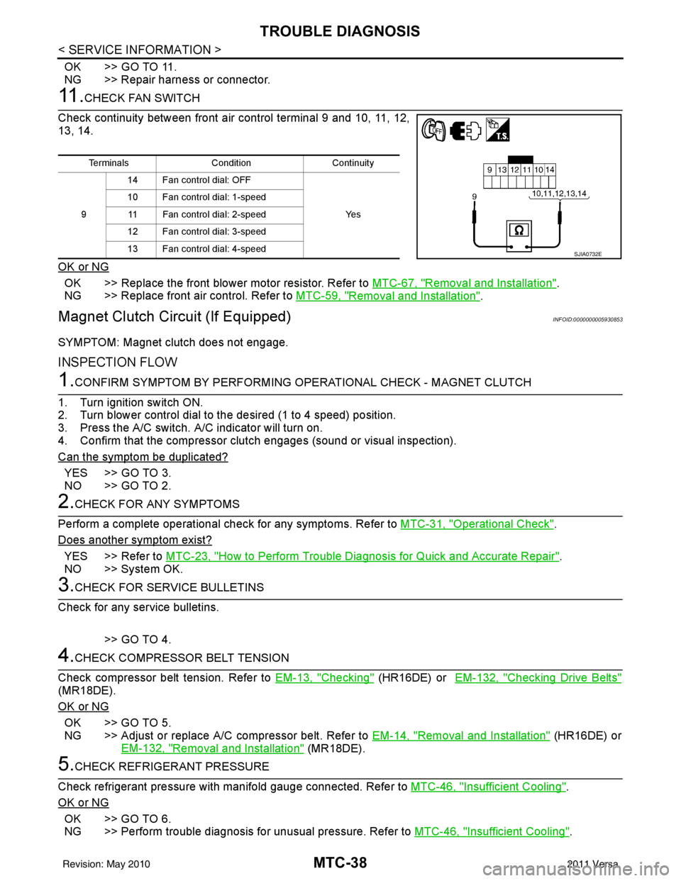
Check continuity between front air control terminal 9 and 10, 11, 12,
13, 14.
OK or NG
OK >> Replace the front blower motor resistor. Refer to MTC-67, "Removal and Installation".
NG >> Replace front air control. Refer to MTC-59, "
Removal and Installation".
Magnet Clutch Circuit (If Equipped)INFOID:0000000005930853
SYMPTOM: Magnet clutch does not engage.
INSPECTION FLOW
1.CONFIRM SYMPTOM BY PERFORMING OP ERATIONAL CHECK - MAGNET CLUTCH
1. Turn ignition switch ON.
2. Turn blower control dial to the desired (1 to 4 speed) position.
3. Press the A/C switch. A/C indicator will turn on.
4. Confirm that the compressor clut ch engages (sound or visual inspection).
Can the symptom be duplicated?
YES >> GO TO 3.
NO >> GO TO 2.
2.CHECK FOR ANY SYMPTOMS
Perform a complete operational check for any symptoms. Refer to MTC-31, "
Operational Check".
Does another symptom exist?
YES >> Refer to MTC-23, "How to Perform Trouble Diagnosis for Quick and Accurate Repair".
NO >> System OK.
3.CHECK FOR SERVICE BULLETINS
Check for any service bulletins.
>> GO TO 4.
4.CHECK COMPRESSOR BELT TENSION
Check compressor belt tension. Refer to EM-13, "
Checking" (HR16DE) or EM-132, "Checking Drive Belts"
(MR18DE).
OK or NG
OK >> GO TO 5.
NG >> Adjust or replace A/C compressor belt. Refer to EM-14, "
Removal and Installation" (HR16DE) or
EM-132, "
Removal and Installation" (MR18DE).
5.CHECK REFRIGERANT PRESSURE
Check refrigerant pressure with manifold gauge connected. Refer to MTC-46, "
Insufficient Cooling".
OK or NG
OK >> GO TO 6.
NG >> Perform trouble diagnosis for unusual pressure. Refer to MTC-46, "
Insufficient Cooling".
TerminalsConditionContinuity
9 14 Fan control dial: OFF
Ye s
10 Fan control dial: 1-speed
11 Fan control dial: 2-speed
12 Fan control dial: 3-speed
13 Fan control dial: 4-speed
SJIA0732E
Revision: May 2010 2011 Versa
Page 3362 of 3787
MTC-46
< SERVICE INFORMATION >
TROUBLE DIAGNOSIS
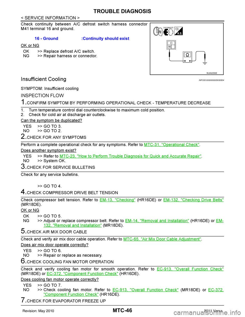
Check continuity between A/C defrost switch harness connector
M41 terminal 16 and ground.
OK or NG
OK >> Replace defrost A/C switch.
NG >> Repair harness or connector.
Insufficient CoolingINFOID:0000000005930854
SYMPTOM: Insufficient cooling
INSPECTION FLOW
1.CONFIRM SYMPTOM BY PERFORMING OPERATIONAL CHECK - TEMPERATURE DECREASE
1. Turn temperature control dial counterclockwise to maximum cold position.
2. Check for cold air at discharge air outlets.
Can the symptom be duplicated?
YES >> GO TO 3.
NO >> GO TO 2.
2.CHECK FOR ANY SYMPTOMS
Perform a complete operational check for any symptoms. Refer to MTC-31, "
Operational Check".
Does another symptom exist?
YES >> Refer to MTC-23, "How to Perform Trouble Diagnosis for Quick and Accurate Repair".
NO >> System OK.
3.CHECK FOR SERVICE BULLETINS
Check for any service bulletins.
>> GO TO 4.
4.CHECK COMPRESSOR DRIVE BELT TENSION
Check compressor belt tension. Refer to EM-13, "
Checking" (HR16DE) or EM-132, "Checking Drive Belts"
(MR18DE).
OK or NG
OK >> GO TO 5.
NG >> Adjust or replace compressor belt. Refer to EM-14, "
Removal and Installation" (HR16DE) or EM-
132, "Removal and Installation" (MR18DE).
5.CHECK AIR MIX DOOR CABLE
Check and verify air mix door cable operation. Refer to MTC-65, "
Air Mix Door Cable Adjustment".
Does air mix door operate correctly?
YES >> GO TO 6.
NO >> Repair or replace as necessary.
6.CHECK COOLING FAN MOTOR OPERATION
Check and verify cooling fan motor for smooth operation. Refer to EC-913, "
Overall Function Check"
(MR18DE) or EC-372, "Component Function Check" (HR16DE).
Does cooling fan motor operate correctly?
YES >> GO TO 7.
NO >> Check cooling fan motor. Refer to EC-913, "
Overall Function Check" (MR18DE) or EC-372,
"Component Function Check" (HR16DE).
7.CHECK FOR EVAPORATOR FREEZE UP16 - Ground :Continuity should exist
WJIA2255E
Revision: May 2010
2011 Versa
Page 3367 of 3787
TROUBLE DIAGNOSISMTC-51
< SERVICE INFORMATION >
C
DE
F
G H
I
K L
M A
B
MTC
N
O P
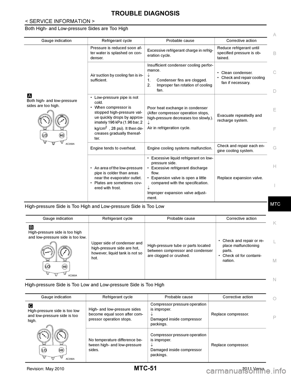
Both High- and Low-pressure Sides are Too High
High-pressure Side is Too High and Low-pressure Side is Too Low
High-pressure Side is Too Low and Low-pressure Side is Too High
Gauge indication
Refrigerant cycle Probable causeCorrective action
Both high- and low-pressure
sides are too high. Pressure is reduced soon af-
ter water is splashed on con-
denser.
Excessive refrigerant charge in refrig-
eration cycle. Reduce refrigerant until
specified pressure is ob-
tained.
Air suction by cooling fan is in-
sufficient. Insufficient condenser cooling perfor-
mance.
↓
1. Condenser fins are clogged.
2. Improper fan rotation of cooling
fan. • Clean condenser.
• Check and repair cooling
fan if necessary.
• Low-pressure pipe is not cold.
• When compressor is
stopped high-pressure val-
ue quickly drops by approx-
imately 196 kPa (1.96 bar, 2
kg/cm
2 , 28 psi). It then de-
creases gradually thereaf-
ter. Poor heat exchange in condenser
(After compressor operation stops,
high-pressure decreases too slowly.).
↓
Air in refrigeration cycle.
Evacuate repeatedly and
recharge system.
Engine tends to overheat. Engine cooling systems malfunction. Check and repair each en-
gine cooling system.
• An area of the low-pressure pipe is colder than areas
near the evaporator outlet.
• Plates are sometimes cov- ered with frost. • Excessive liquid refrigerant on low-
pressure side.
• Excessive refrigerant discharge flow.
• Expansion valve is open a little
compared with the specification.
↓
Improper expansion valve adjust-
ment. Replace expansion valve.
AC359A
Gauge indication
Refrigerant cycle Probable causeCorrective action
High-pressure side is too high
and low-pressure side is too low. Upper side of condenser and
high-pressure side are hot,
however, liquid tank is not so
hot.High-pressure tube or parts located
between compressor and condenser
are clogged or crushed. • Check and repair or re-
place malfunctioning
parts.
• Check oil for contami- nation.
AC360A
Gauge indication Refrigerant cycle Probable causeCorrective action
High-pressure side is too low
and low-pressure side is too
high. High- and low-pressure sides
become equal soon after com-
pressor operation stops. Compressor pressure operation
is improper.
↓
Damaged inside compressor
packings.
Replace compressor.
No temperature difference be-
tween high- and low-pressure
sides. Compressor pressure operation
is improper.
↓
Damaged inside compressor
packings.
Replace compressor.
AC356A
Revision: May 2010
2011 Versa
Page 3369 of 3787
TROUBLE DIAGNOSISMTC-53
< SERVICE INFORMATION >
C
DE
F
G H
I
K L
M A
B
MTC
N
O P
Insufficient HeatingINFOID:0000000005930855
SYMPTOM: Insufficient heating
INSPECTION FLOW
1.CONFIRM SYMPTOM BY PERFORMING OPERAT IONAL CHECK - TEMPERATURE INCREASE
1. Turn temperature control dial clockwise to maximum heat position.
2. Check for hot air at discharge air outlets.
Can the symptom be duplicated?
YES >> GO TO 3.
NO >> GO TO 2.
2.CHECK FOR ANY SYMPTOMS
Perform a complete operational check for any symptoms. Refer to MTC-31, "
Operational Check" .
Does another symptom exist?
YES >> Refer to MTC-23, "How to Perform Trouble Diagnosis for Quick and Accurate Repair" .
NO >> System OK.
3.CHECK FOR SERVICE BULLETINS
Check for any service bulletins.
>> GO TO 4.
4.CHECK COOLANT SYSTEM
1. Check engine coolant level. Refer to CO-11, "
Inspection" (HR16DE) or CO-36, "Inspection" (MR18DE).
2. Check hoses for leaks or kinks.
3. Check Radiator cap. Refer to CO-14, "
Checking Radiator Cap" HR16DE or CO-39, "Checking Radiator
Cap" (MR18DE).
OK or NG
OK >> GO TO 5.
NG >> Repair/replace as necessary.
5.CHECK AIR MIX DOOR CABLE
Check air mix door cable operation. Refer to MTC-65, "
Air Mix Door Cable Adjustment" .
OK or NG
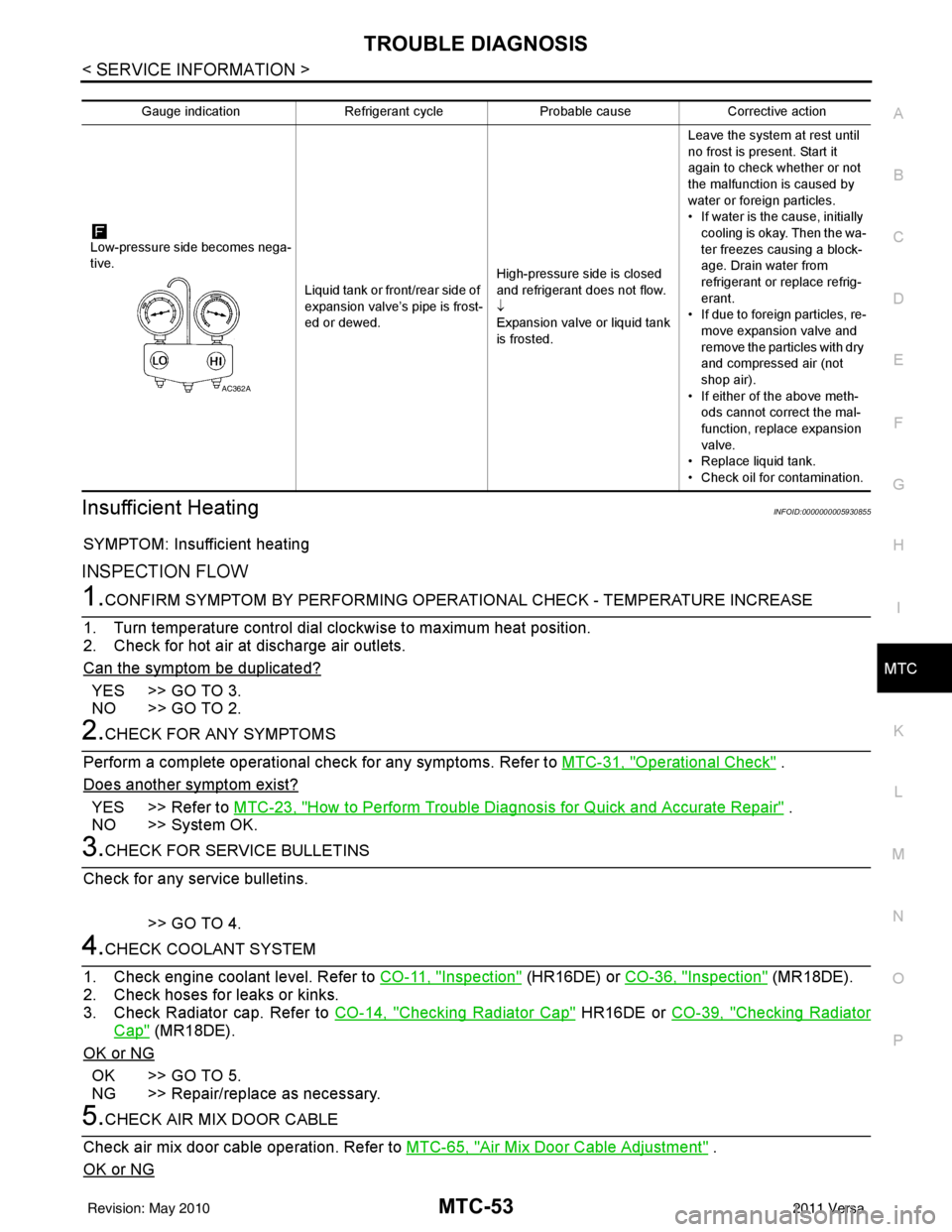
Gauge indication Refrigerant cycleProbable causeCorrective action
Low-pressure side becomes nega-
tive. Liquid tank or front/rear side of
expansion valve’s pipe is frost-
ed or dewed.High-pressure side is closed
and refrigerant does not flow.
↓
Expansion valve or liquid tank
is frosted.Leave the system at rest until
no frost is present. Start it
again to check whether or not
the malfunction is caused by
water or foreign particles.
• If water is the cause, initially
cooling is okay. Then the wa-
ter freezes causing a block-
age. Drain water from
refrigerant or replace refrig-
erant.
• If due to foreign particles, re-
move expansion valve and
remove the particles with dry
and compressed air (not
shop air).
• If either of the above meth- ods cannot correct the mal-
function, replace expansion
valve.
• Replace liquid tank.
• Check oil for contamination.
AC362A
Revision: May 2010 2011 Versa
Page 3371 of 3787
TROUBLE DIAGNOSISMTC-55
< SERVICE INFORMATION >
C
DE
F
G H
I
K L
M A
B
MTC
N
O P
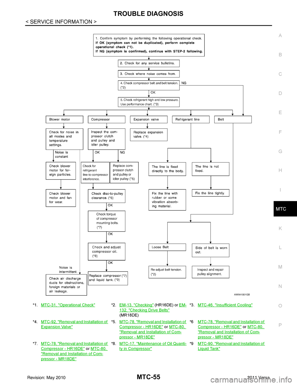
*1. MTC-31, "Operational Check"*2.EM-13, "Checking" (HR16DE) or EM-
132, "Checking Drive Belts"
(MR18DE) *3.
MTC-46, "
Insufficient Cooling"
*4.MTC-92, "Removal and Installation of
Expansion Valve"
*5.MTC-78, "Removal and Installation of
Compressor - HR16DE" or MTC-80,
"Removal and Installation of Com-
pressor - MR18DE"
*6 MTC-78, "Removal and Installation of
Compressor - HR16DE" or MTC-80,
"Removal and Installation of Com-
pressor - MR18DE"
*7. MTC-78, "Removal and Installation of
Compressor - HR16DE" or MTC-80,
"Removal and Installation of Com-
pressor - MR18DE"
*8.MTC-17, "Maintenance of Oil Quanti-
ty in Compressor"
*9 MTC-90, "Removal and Installation of
Liquid Tank"
AWIIA1001GB
Revision: May 2010 2011 Versa
Page 3375 of 3787
A/C UNIT ASSEMBLYMTC-59
< SERVICE INFORMATION >
C
DE
F
G H
I
K L
M A
B
MTC
N
O P
A/C UNIT ASSEMBLY
Removal and InstallationINFOID:0000000005930860
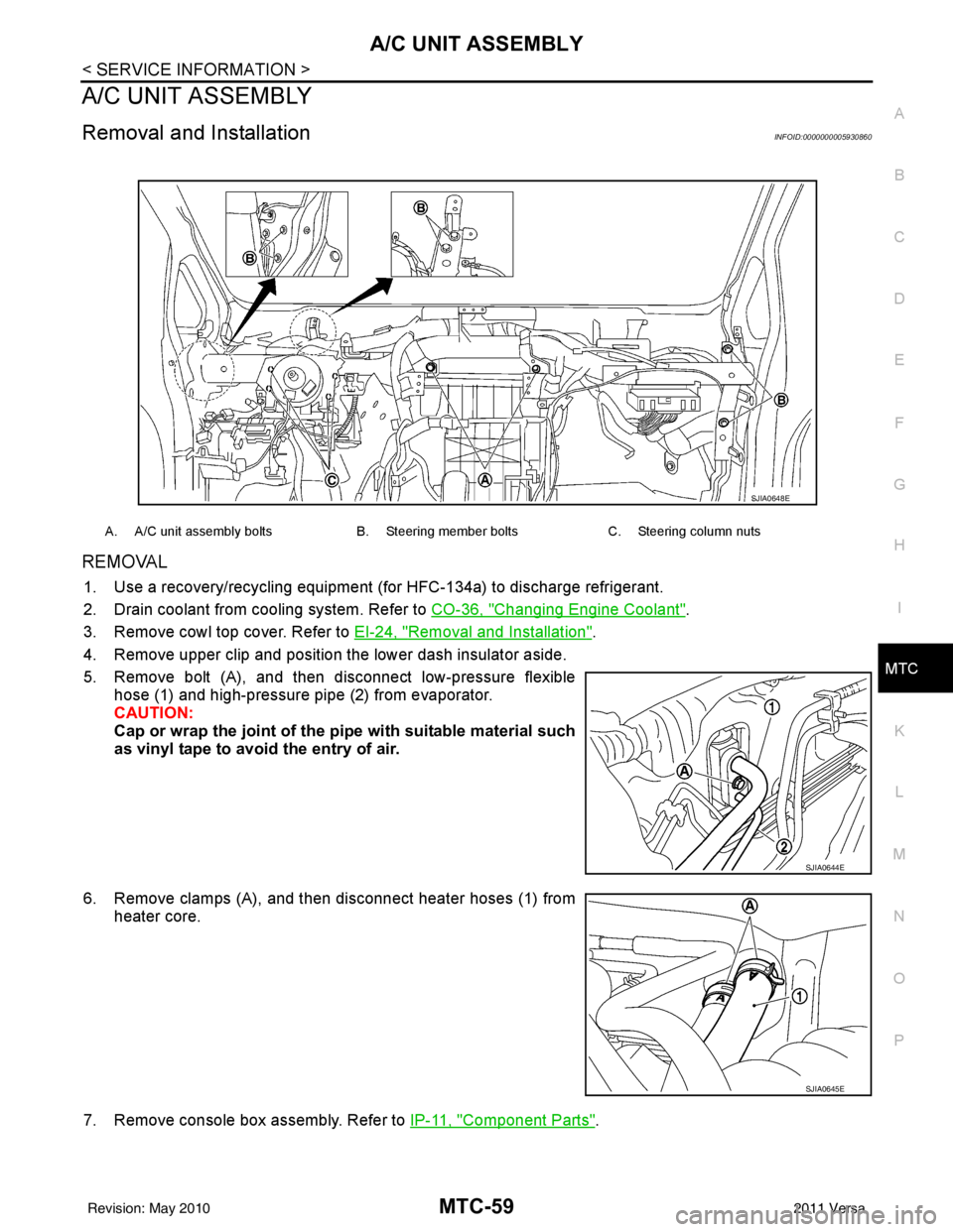
REMOVAL
1. Use a recovery/recycling equipment (f or HFC-134a) to discharge refrigerant.
2. Drain coolant from cooling system. Refer to CO-36, "
Changing Engine Coolant".
3. Remove cowl top cover. Refer to EI-24, "
Removal and Installation".
4. Remove upper clip and position the lower dash insulator aside.
5. Remove bolt (A), and then disconnect low-pressure flexible hose (1) and high-pressure pipe (2) from evaporator.
CAUTION:
Cap or wrap the joint of the pi pe with suitable material such
as vinyl tape to avoid the entry of air.
6. Remove clamps (A), and then disconnect heater hoses (1) from heater core.
7. Remove console box assembly. Refer to IP-11, "
Component Parts".
A. A/C unit assembly boltsB. Steering member boltsC. Steering column nuts
SJIA0648E
SJIA0644E
SJIA0645E
Revision: May 2010 2011 Versa
Page 3391 of 3787
REFRIGERANT LINESMTC-75
< SERVICE INFORMATION >
C
DE
F
G H
I
K L
M A
B
MTC
N
O P
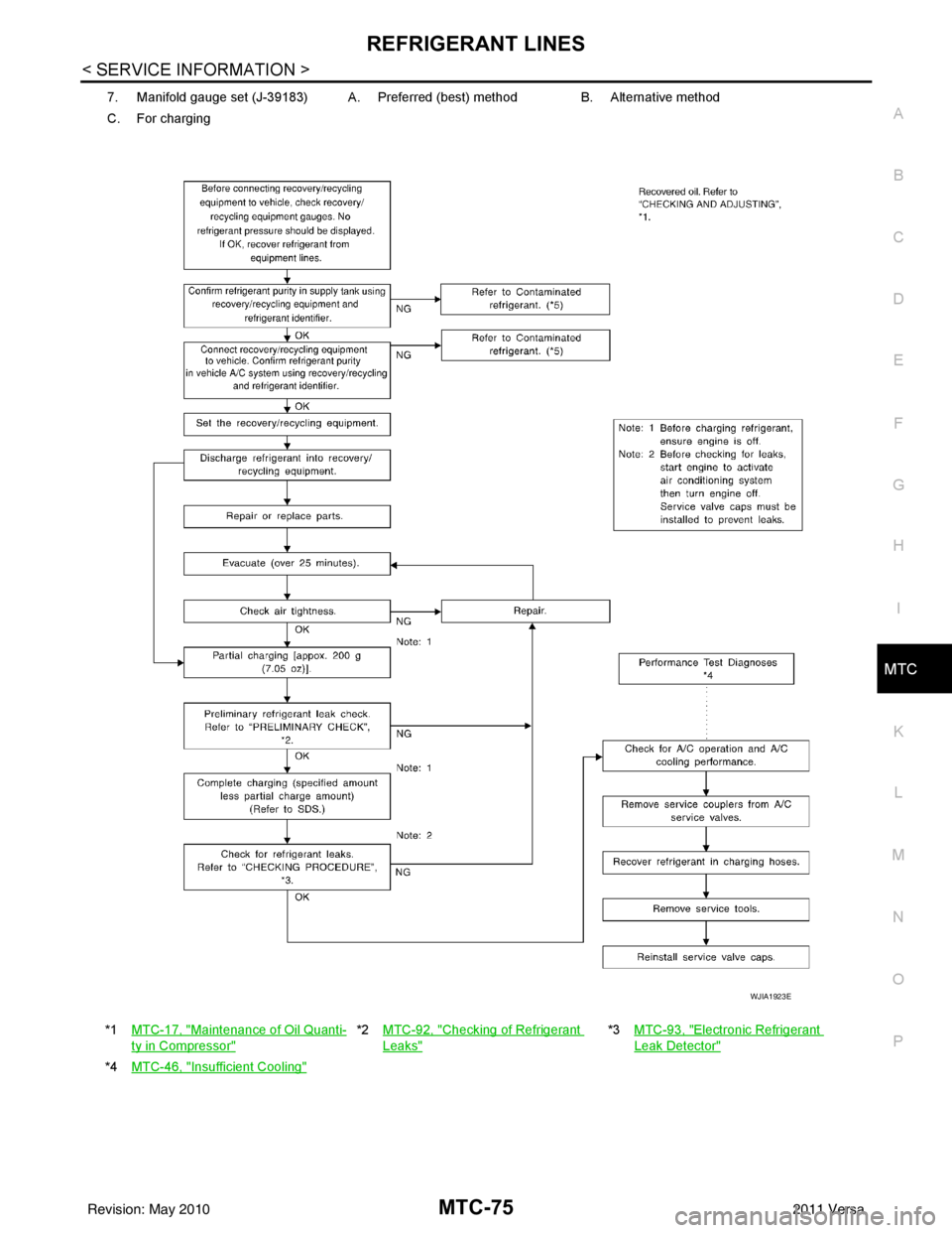
7. Manifold gauge set (J-39183) A. Prefe rred (best) method B. Alternative method
C. For charging
*1 MTC-17, "
Maintenance of Oil Quanti-
ty in Compressor"
*2MTC-92, "Checking of Refrigerant
Leaks"
*3 MTC-93, "Electronic Refrigerant
Leak Detector"
*4MTC-46, "Insufficient Cooling"
WJIA1923E
Revision: May 2010 2011 Versa
Page 3410 of 3787
MTC-94
< SERVICE INFORMATION >
REFRIGERANT LINES
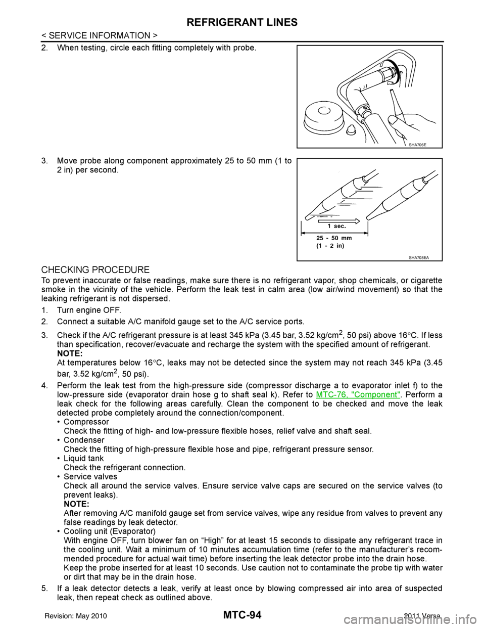
2. When testing, circle each fitting completely with probe.
3. Move probe along component approximately 25 to 50 mm (1 to2 in) per second.
CHECKING PROCEDURE
To prevent inaccurate or false readings, make sure there is no refrigerant vapor, shop chemicals, or cigarette
smoke in the vicinity of the vehicle. Perform the leak test in calm area (low air/wind movement) so that the
leaking refrigerant is not dispersed.
1. Turn engine OFF.
2. Connect a suitable A/C manifold gauge set to the A/C service ports.
3. Check if the A/C refrigerant pressure is at least 345 kPa (3.45 bar, 3.52 kg/cm
2, 50 psi) above 16°C. If less
than specification, recover/evacuate and recharge the system with the specified amount of refrigerant.
NOTE:
At temperatures below 16 °C, leaks may not be detected since t he system may not reach 345 kPa (3.45
bar, 3.52 kg/cm
2, 50 psi).
4. Perform the leak test from the high-pressure side (compressor dischar ge a to evaporator inlet f) to the
low-pressure side (evaporator drain hose g to shaft seal k). Refer to MTC-76, "
Component". Perform a
leak check for the following areas carefully. Clean the component to be checked and move the leak
detected probe completely around the connection/component.
• Compressor Check the fitting of high- and low-pressure flexible hoses, relief valve and shaft seal.
• Condenser Check the fitting of high-pressure flexible hose and pipe, refrigerant pressure sensor.
• Liquid tank Check the refrigerant connection.
• Service valves
Check all around the service valves. Ensure service valve caps are secured on the service valves (to
prevent leaks).
NOTE:
After removing A/C manifold gauge set from service valves, wipe any residue from valves to prevent any
false readings by leak detector.
• Cooling unit (Evaporator)
With engine OFF, turn blower fan on “High” for at l east 15 seconds to dissipate any refrigerant trace in
the cooling unit. Wait a minimum of 10 minutes accumulation time (refer to the manufacturer’s recom-
mended procedure for actual wait time) before insert ing the leak detector probe into the drain hose.
Keep the probe inserted for at least 10 seconds. Use c aution not to contaminate the probe tip with water
or dirt that may be in the drain hose.
5. If a leak detector detects a leak, verify at least once by blowing compressed air into area of suspected
leak, then repeat check as outlined above.
SHA706E
SHA708EA
Revision: May 2010 2011 Versa