Page 3459 of 3787
HARNESSPG-39
< SERVICE INFORMATION >
C
DE
F
G H
I
J
L
M A
B
PG
N
O P
HARNESS
Harness LayoutINFOID:0000000005928355
HOW TO READ HARNESS LAYOUT
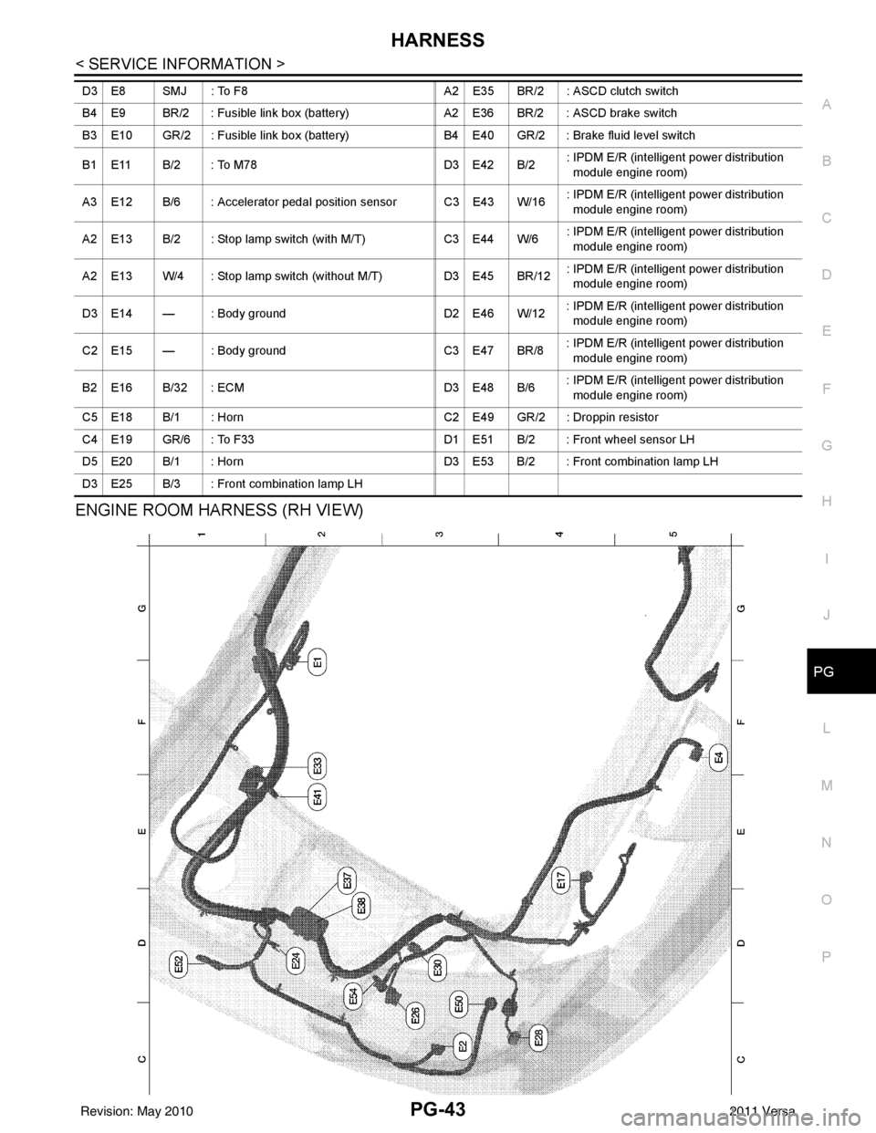
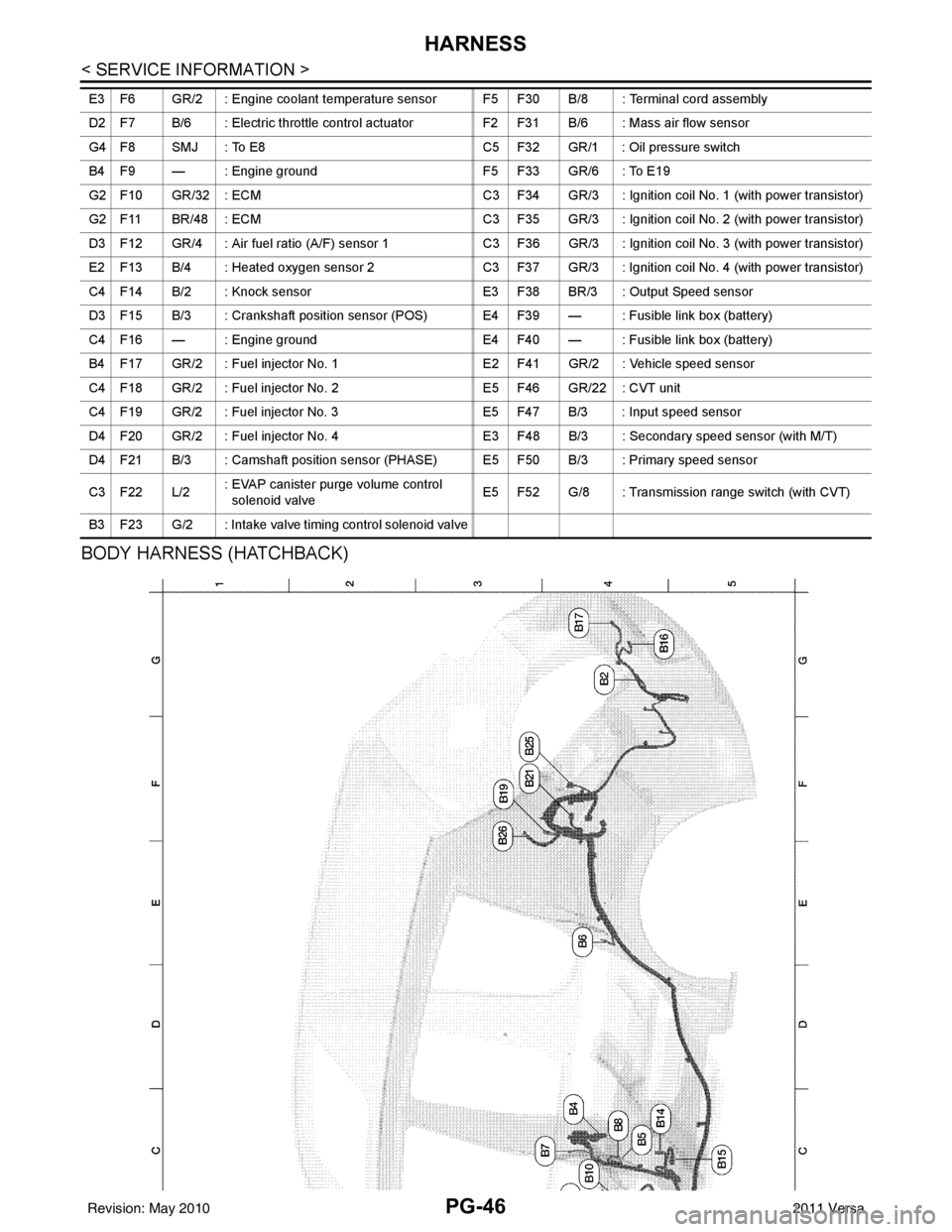
The following Harness Layouts use a map style grid to help locate
connectors on the drawings:
• Main Harness
• Engine Room Harness (LH View)
• Engine Room Harness (RH View)
• Engine Control Harness
• Body Harness (Hatchback)
• Body Harness (Sedan)
• Body No. 2 Harness (Hatchback)
• Body No. 2 Harness (Sedan)
• Room Lamp Harness
• Back Door Harness (Hatchback)
To use the grid reference
1. Find the desired connector number on the connector list.
2. Find the grid reference.
3. On the drawing, find the crossing of the grid reference letter column and number row.
4. Find the connector number in the crossing zone.
5. Follow the line to the connector.
OUTLINE
SEL252V
WKIA5996E
Revision: May 2010 2011 Versa
Page 3462 of 3787
PG-42
< SERVICE INFORMATION >
HARNESS
ENGINE ROOM HARNESS (LH VIEW)
Refer to "ENGINE ROOM HARNESS (RH VIEW)" for continuation of engine room harness.
ABMIA2318GB
C4 E3 GR/4 : Cooling fan motor (without A/C) E4 E27 B/2 : Front fog lamp LH
C4 E3 B/2 : Cooling fan motor (with A/C) D4 E29 B/2 : Front combination lamp LH
C4 E5 GR/3 : Resistor B1 E31 W/24 : TCM
C3 E6 — : Fuse and fusible link box B1 E32 GR/24 : TCM
B1 E7 SMJ : To M69 A2 E34 BR/2 : Clutch interlock switch
Revision: May 2010 2011 Versa
Page 3463 of 3787

HARNESSPG-43
< SERVICE INFORMATION >
C
DE
F
G H
I
J
L
M A
B
PG
N
O P
ENGINE ROOM HARNESS (RH VIEW)
D3 E8 SMJ : To F8 A2 E35 BR/2 : ASCD clutch switch
B4 E9 BR/2 : Fusible link box (battery) A2 E36 BR/2 : ASCD brake switch
B3 E10 GR/2 : Fusible link box (battery) B4 E40 GR/2 : Brake fluid level switch
B1 E11 B/2 : To M78 D3 E42 B/2: IPDM E/R (intelligent power distribution
module engine room)
A3 E12 B/6 : Accelerator pedal position sensor C3 E43 W/16 : IPDM E/R (intelligent power distribution
module engine room)
A2 E13 B/2 : Stop lamp switch (with M/T) C3 E44 W/6: IPDM E/R (intelligent power distribution
module engine room)
A2 E13 W/4 : Stop lamp switch (without M/T) D3 E45 BR/12: IPDM E/R (intelligent power distribution
module engine room)
D3 E14 — : Body ground D2 E46 W/12: IPDM E/R (intelligent power distribution
module engine room)
C2 E15 — : Body ground C3 E47 BR/8: IPDM E/R (intelligent power distribution
module engine room)
B2 E16 B/32 : ECM D3 E48 B/6: IPDM E/R (intelligent power distribution
module engine room)
C5 E18 B/1 : Horn C2 E49 GR/2 : Droppin resistor
C4 E19 GR/6 : To F33 D1 E51 B/2 : Front wheel sensor LH
D5 E20 B/1 : Horn D3 E53 B/2 : Front combination lamp LH
D3 E25 B/3 : Front combination lamp LH
Revision: May 2010 2011 Versa
Page 3464 of 3787
PG-44
< SERVICE INFORMATION >
HARNESS
Refer to "ENGINE ROOM HARNESS (LH VIEW)" for continuation of engine room harness.
G2 E1 GR/5 : Front wiper motor F2 E33 B/26 : ABS actuator and electric unit (control unit)
C3 E2 B/2 : Front and rear washer motor E2 E37 B/5 : Daytime light relay 1
F5 E4 Y/2 : Crash zone sensor D2 E38 L/5 : Daytime light relay 2
E4 E17 B/3 : Refrigerant pressure sensor E2 E41 — : Ground (ABS)
D2 E24 — : Engine ground C3 E50 W/2 : Washer fluid level switch
C3 E26 B/3 : Front combination lamp RH D1 E52 B/2 : Front wheel sensor RH
C4 E28 B/2 : Front fog lamp RH D2 E54 B/2 : Front combination lamp RH
D3 E30 B/2 : Front combination lamp RH
Revision: May 2010 2011 Versa
Page 3465 of 3787
HARNESSPG-45
< SERVICE INFORMATION >
C
DE
F
G H
I
J
L
M A
B
PG
N
O P
ENGINE CONTROL HARNESS
ABMIA2319GB
B4 F1 B/3 : Generator E5 F24 G/3: Park/neutral position (PNP) switch
(with M/T)
B5 F2 — : Generator F5 F25 B/10 : Transmission range switch (with A/T)
B5 F3 B/1 : A/C compress orC3 F26 W/2 : Condenser-2
B4 F4 — : Generator C5 F27 — : Starter motor
A4 F5 — : Body ground C5 F28 — : Starter motor
Revision: May 2010 2011 Versa
Page 3466 of 3787

PG-46
< SERVICE INFORMATION >
HARNESS
BODY HARNESS (HATCHBACK)
E3 F6 GR/2 : Engine coolant temperature sensor F5 F30 B/8 : Terminal cord assembly
D2 F7 B/6 : Electric throttle control actuatorF2 F31 B/6 : Mass air flow sensor
G4 F8 SMJ : To E8 C5 F32 GR/1 : Oil pressure switch
B4 F9 — : Engine ground F5 F33 GR/6 : To E19
G2 F10 GR/32 : ECM C3 F34 GR/3 : Ignition coil No. 1 (with power transistor)
G2 F11 BR/48 : ECM C3 F35 GR/3 : Ignition coil No. 2 (with power transistor)
D3 F12 GR/4 : Air fuel ratio (A/F) sensor 1 C3 F36 GR/3 : Ignition coil No. 3 (with power transistor)
E2 F13 B/4 : Heated oxygen sensor 2 C3 F37 GR/3 : Ignition coil No. 4 (with power transistor)
C4 F14 B/2 : Knock sensor E3 F38 BR/3 : Output Speed sensor
D3 F15 B/3 : Crankshaft position sensor (POS) E4 F39 — : Fusible link box (battery)
C4 F16 — : Engine ground E4 F40 — : Fusible link box (battery)
B4 F17 GR/2 : Fuel injector No. 1 E2 F41 GR/2 : Vehicle speed sensor
C4 F18 GR/2 : Fuel injector No. 2E5 F46 GR/22 : CVT unit
C4 F19 GR/2 : Fuel injector No. 3 E5 F47 B/3 : Input speed sensor
D4 F20 GR/2 : Fuel injector No. 4 E3 F48 B/3 : Secondary speed sensor (with M/T)
D4 F21 B/3 : Camshaft position sensor (PHASE) E5 F50 B/3 : Primary speed sensor
C3 F22 L/2 : EVAP canister purge volume control
solenoid valve E5 F52 G/8 : Transmission range switch (with CVT)
B3 F23 G/2 : Intake valve timing control solenoid valve
Revision: May 2010 2011 Versa
Page 3478 of 3787

PG-58
< SERVICE INFORMATION >
HARNESS
Wiring Diagram Codes (Cell Codes)
INFOID:0000000005928356
Use the chart below to find out what each wiring diagram code stands for.
Refer to the wiring diagram code in the alphabetical index to find the location (page number) of each wiring
diagram.
D4 D406 W/2 : Back door request switch C2 D413 B/1 : Rear window defogger (-)
E2 D407 W/2 : High mounted stop lamp
Code Section Wiring Diagram Name
ABS BRC Anti-lock Brake System
A/C,M MTC Manual Air Conditioner
APPS1 EC Accelerator Pedal Position Sensor
A/F EC Air Fuel Ratio Sensor 1
A/FH EC Air Fuel Ratio Sensor 1 Heater
APPS2 EC Accelerator Pedal Position Sensor
APPS3 EC Accelerator Pedal Position Sensor
ASC/BS EC ASCD Brake Switch
ASC/SW EC ASCD Steering Switch
ASCBOF EC ASCD Brake Switch
ASCIND EC ASCD Indicator
AT/IND DI A/T Indicator Lamp
AUDIO AV Audio
BACK/L LT Back-up Lamp
BA/FTS AT A/T Fluid Temperature Sensor and TCM Power Supply
B/DOOR BL Back Door Opener
BRK/SW EC Brake Switch
CAN AT CAN Communication Line
CAN CVT CAN Communication Line
CAN EC CAN Communication Line
CAN LAN CAN System
CHARGE SC Charging System
CHIME DI Warning Chime
COOL/F EC Cooling Fan Control
COMBSW LT Combination Switch
COMM AV Audio Visual Communication System
CVTIND DI CVT Indicator Lamp
D/LOCK BL Power Door Lock
DEF GW Rear Window Defogger
DTRL LT Headlamp - With Daytime Light System
ECTS EC Engine Coolant Temperature Sensor
ENGSS AT Engine Speed Signal
EPS STC Electronic Controlled Power Steering
ETC1 EC Electric Throttle Control Function
ETC2 EC Throttle Control Motor Relay
ETC3 EC Throttle Control Motor
F/FOG LT Front Fog Lamp
F/PUMP EC Fuel Pump
FTS AT A/T Fluid Temperature Sensor
FTS CVT CVT Fluid Temperature Sensor Circuit
FTTS EC Fuel Tank Temperature Sensor
FUEL EC Fuel Ignition System Function
HEATER MTC Heater System
Revision: May 2010 2011 Versa
Page 3481 of 3787
ELECTRICAL UNITS LOCATIONPG-61
< SERVICE INFORMATION >
C
DE
F
G H
I
J
L
M A
B
PG
N
O P
ELECTRICAL UNITS LOCATION
Electrical Units LocationINFOID:0000000005928357
ENGINE COMPARTMENT
ABMIA2326GB
Revision: May 2010 2011 Versa