Page 485 of 3787
![NISSAN TIIDA 2011 Service Repair Manual AV-88
< SERVICE INFORMATION >[AUDIO WITH NAVIGATION]
TELEPHONE
Hatchback
Sedan
Removal
1. Disconnect the battery negative terminal.
2. For hatchback, remove luggage side lower finisher (RH). Refer to NISSAN TIIDA 2011 Service Repair Manual AV-88
< SERVICE INFORMATION >[AUDIO WITH NAVIGATION]
TELEPHONE
Hatchback
Sedan
Removal
1. Disconnect the battery negative terminal.
2. For hatchback, remove luggage side lower finisher (RH). Refer to](/manual-img/5/57396/w960_57396-484.png)
AV-88
< SERVICE INFORMATION >[AUDIO WITH NAVIGATION]
TELEPHONE
Hatchback
Sedan
Removal
1. Disconnect the battery negative terminal.
2. For hatchback, remove luggage side lower finisher (RH). Refer to EI-56, "
Removal and Installation".
3. For sedan, fold the rear seat back down, re move the seat back finisher (RH). Refer to EI-59, "
Removal
and Installation".
4. Disconnect the Bluetooth antenna feeder harness clips.
5. Disconnect the Bluetooth ant enna feeder harness connector.
6. Remove the Bluetooth antenna bracket bolt(s) and remove antenna.
7. Remove the Bluetooth antenna screws and remove bracket.
Installation
Installation is in the reverse order of removal.
LKIA0763E
1. Bluetooth antenna bracket 2. Bluetooth antenna A. Bluetooth antenna bracket bolts
B. Bluetooth antenna screws C. Bluetooth antenna feeder harness
clips
LKIA0937E
1. Bluetooth antenna bracket 2. Bluetooth antenna A. Bluetooth antenna bracket bolts
B. Bluetooth antenna screws C. Bluetooth antenna feeder harness
clip Front
Revision: May 2010
2011 Versa
Page 486 of 3787
TELEPHONEAV-89
< SERVICE INFORMATION > [AUDIO WITH NAVIGATION]
C
D
E
F
G H
I
J
L
M A
B
AV
N
O P
BLUETOOTH MICROPHONE
Removal
1. Remove over-head console assembly, roof finisher. Refer to EI-50.
2. Remove the Bluetooth microphone.
Installation
Installation is in the reverse order of removal.
Revision: May 2010 2011 Versa
Page 487 of 3787
AV-90
< SERVICE INFORMATION >[AUDIO WITH NAVIGATION]
USB CONNECTOR AND AUX JACK
USB CONNECTOR AND AUX JACK
Removal and InstallationINFOID:0000000005931335
REMOVAL
1. Remove the cluster lid C. Refer to
IP-11, "Component Parts".
2. Push the pawl from the back of the cluster lid C to remove the USB connector and aux jack (1).
INSTALLATION
Installation is in the reverse order of removal.
ALNIA1245ZZ
Revision: May 2010 2011 Versa
Page 488 of 3787
AUDIO ANTENNAAV-91
< SERVICE INFORMATION > [AUDIO WITH NAVIGATION]
C
D
E
F
G H
I
J
L
M A
B
AV
N
O P
AUDIO ANTENNA
Location of AntennaINFOID:0000000006216724
Removal and Installati on of Roof AntennaINFOID:0000000005931337
REMOVAL
1. For hatchback, remove the luggage side upper finisher (LH). Refer to EI-56.
2. For sedan, remove the rear pillar finisher. Refer to EI-54, "
Removal and Installation - Sedan".
3. Remove rear assist grip (LH). Refer to EI-50
.
4. Remove three clips of headlining (rear side). Pull down headlining (rear side) and obtain space for work between vehicle and headlining.
5. Disconnect the roof antenna harness connectors.
6. Remove nut (A) and clips (B).
LKIA0934E
1. Roof antenna 2. Roof antenna base3. AV control unit
A. Audio antenna harness connector B. Harness clips C. Roof antenna harness connectors
Revision: May 2010 2011 Versa
Page 489 of 3787
AV-92
< SERVICE INFORMATION >[AUDIO WITH NAVIGATION]
AUDIO ANTENNA
• : Vehicle front
7. Remove the roof antenna.
INSTALLATION
Installation is in the reverse order of removal.
SKIB4772E
Revision: May 2010 2011 Versa
Page 490 of 3787
GPS ANTENNAAV-93
< SERVICE INFORMATION > [AUDIO WITH NAVIGATION]
C
D
E
F
G H
I
J
L
M A
B
AV
N
O P
GPS ANTENNA
Location of AntennaINFOID:0000000006216725
Removal and Installation of GPS AntennaINFOID:0000000006412036
1. Remove cluster lid C.Refer to IP-12, "Removal and Installation"
2. Remove audio unit and disconnect GPS antenna connector.
3. Remove screw (A) and remove GPS antenna (1).
AWNIA2217ZZ
1. GPS antenna 2. AV control unit
ALNIA2211ZZ
Revision: May 2010 2011 Versa
Page 2833 of 3787

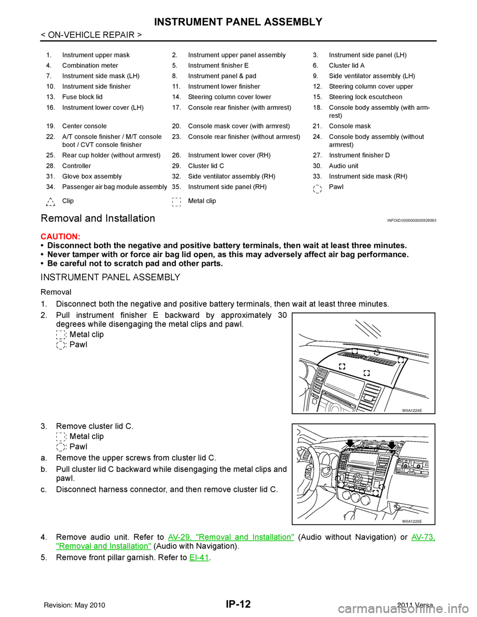
IP-12
< ON-VEHICLE REPAIR >
INSTRUMENT PANEL ASSEMBLY
Removal and Installation
INFOID:0000000005929593
CAUTION:
• Disconnect both the negative and positive battery terminals, then wait at least three minutes.
• Never tamper with or force air bag lid open, as this may adversely affect air bag performance.
• Be careful not to scratch pad and other parts.
INSTRUMENT PANEL ASSEMBLY
Removal
1. Disconnect both the negative and positive battery terminals, then wait at least three minutes.
2. Pull instrument finisher E backward by approximately 30
degrees while disengaging the metal clips and pawl.
: Metal clip
: Pawl
3. Remove cluster lid C. : Metal clip
: Pawl
a. Remove the upper screws from cluster lid C.
b. Pull cluster lid C backward while disengaging the metal clips and pawl.
c. Disconnect harness connector, and then remove cluster lid C.
4. Remove audio unit. Refer to AV-29, "
Removal and Installation" (Audio without Navigation) or AV-73,
"Removal and Installation" (Audio with Navigation).
5. Remove front pillar garnish. Refer to EI-41
.
1. Instrument upper mask 2. Instrument upper panel assembly 3. Instrument side panel (LH)
4. Combination meter 5. Instrument finisher E 6. Cluster lid A
7. Instrument side mask (LH) 8. Instrument panel & pad 9. Side ventilator assembly (LH)
10. Instrument side finisher 11. Instrument lower finisher 12. Steering column cover upper
13. Fuse block lid 14. Steering column cover lower 15. Steering lock escutcheon
16. Instrument lower cover (LH) 17. Console rear finisher (with armrest) 18. Console body assembly (with arm- rest)
19. Center console 20. Console mask cover (with armrest) 21. Console mask
22. A/T console finisher / M/T console boot / CVT console finisher 23. Console rear finisher (without armrest) 24. Console body assembly (without
armrest)
25. Rear cup holder (without armrest) 26. Instrument lower cover (RH) 27. Instrument finisher D
28. Controller 29. Cluster lid C 30. Audio unit
31. Glove box assembly 32. Side ventilator assembly (RH) 33. Instrument side mask (RH)
34. Passenger air bag module assembly 35. Instrument side panel (RH) Pawl
Clip Metal clip
WIIA1224E
WIIA1225E
Revision: May 2010 2011 Versa
Page 3586 of 3787

SC-8
< SERVICE INFORMATION >
BATTERY
INSTALLATION (All except MR18DE with CVT)
Installation is in the reverse order of removal.
CAUTION:
When connecting, connect the battery positive terminal first.
Reset electronic systems as necessary. Refer to SC-8, "
Required Procedure After Battery Disconnection".
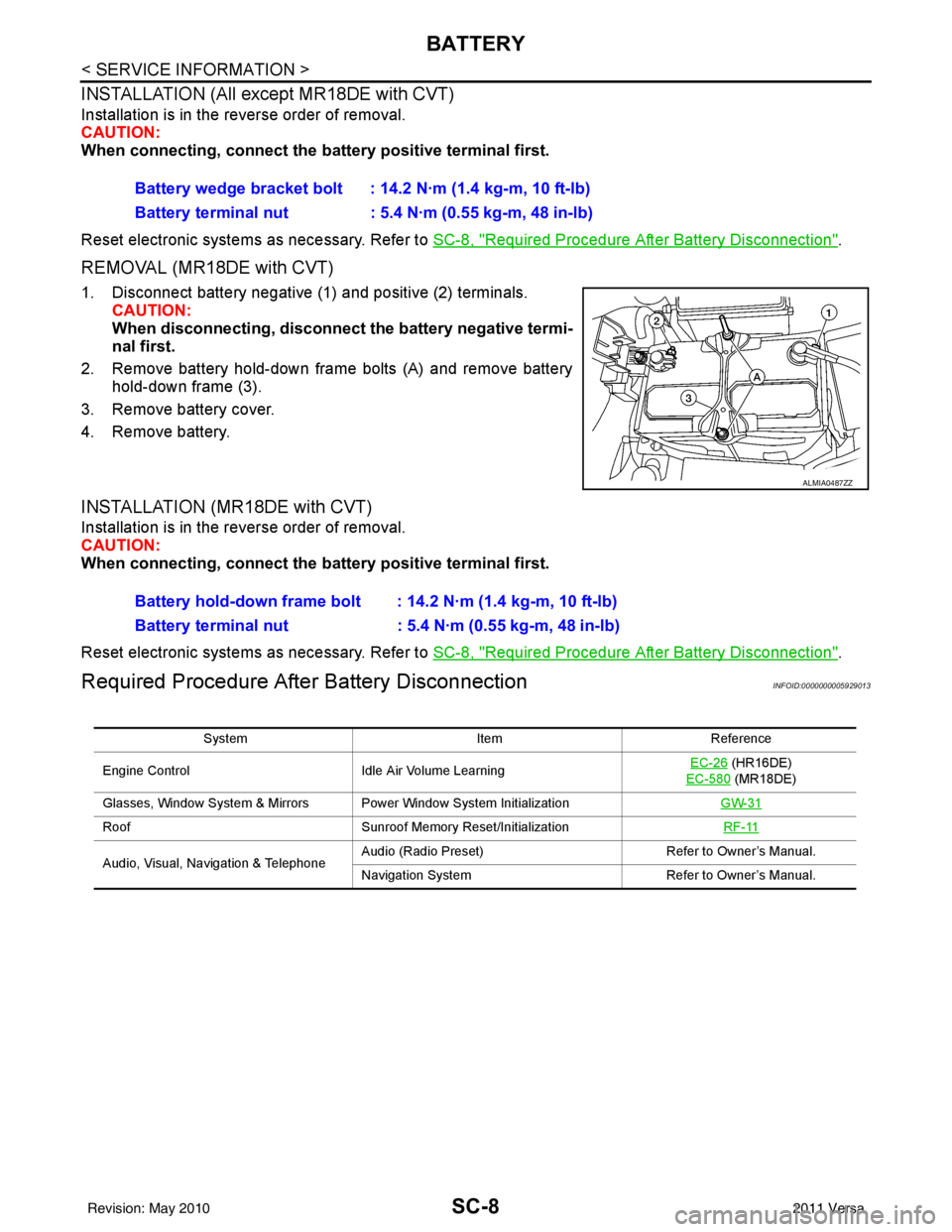
REMOVAL (MR18DE with CVT)
1. Disconnect battery negative (1) and positive (2) terminals.
CAUTION:
When disconnecting, disconnect the battery negative termi-
nal first.
2. Remove battery hold-down frame bolts (A) and remove battery hold-down frame (3).
3. Remove battery cover.
4. Remove battery.
INSTALLATION (MR18DE with CVT)
Installation is in the reverse order of removal.
CAUTION:
When connecting, connect the battery positive terminal first.
Reset electronic systems as necessary. Refer to SC-8, "
Required Procedure After Battery Disconnection".
Required Procedure After Battery DisconnectionINFOID:0000000005929013
Battery wedge bracket bolt : 14.2 N·m (1.4 kg-m, 10 ft-lb)
Battery terminal nut : 5.4 N·m (0.55 kg-m, 48 in-lb)
ALMIA0487ZZ
Battery hold-down frame bolt : 14.2 N·m (1.4 kg-m, 10 ft-lb)
Battery terminal nut : 5.4 N·m (0.55 kg-m, 48 in-lb)
System ItemReference
Engine Control Idle Air Volume Learning EC-26
(HR16DE)
EC-580
(MR18DE)
Glasses, Window System & Mirrors Power Window System Initialization GW-31
RoofSunroof Memory Reset/Initialization RF-11
Audio, Visual, Navigation & TelephoneAudio (Radio Preset)
Refer to Owner’s Manual.
Navigation System Refer to Owner’s Manual.
Revision: May 2010 2011 Versa