2011 NISSAN TIIDA heater
[x] Cancel search: heaterPage 2593 of 3787
![NISSAN TIIDA 2011 Service Repair Manual CYLINDER BLOCKEM-203
< SERVICE INFORMATION > [MR18DE]
C
D
E
F
G H
I
J
K L
M A
EM
NP
O
Disassembly and AssemblyINFOID:0000000005931033
DISASSEMBLY
1. Remove engine and transaxle assembly from vehicle, NISSAN TIIDA 2011 Service Repair Manual CYLINDER BLOCKEM-203
< SERVICE INFORMATION > [MR18DE]
C
D
E
F
G H
I
J
K L
M A
EM
NP
O
Disassembly and AssemblyINFOID:0000000005931033
DISASSEMBLY
1. Remove engine and transaxle assembly from vehicle,](/manual-img/5/57396/w960_57396-2592.png)
CYLINDER BLOCKEM-203
< SERVICE INFORMATION > [MR18DE]
C
D
E
F
G H
I
J
K L
M A
EM
NP
O
Disassembly and AssemblyINFOID:0000000005931033
DISASSEMBLY
1. Remove engine and transaxle assembly from vehicle, separate transaxle from engine. Refer to
EM-197.
2. Install engine to engine stand as follows;
a. Remove flywheel (M/T models) or drive plate (1) (A/T or CVT models).
• Secure flywheel (M/T models) or drive plate (A/T or CVT mod-els) using Tool (A), and remove bolts.
CAUTION:
Be careful not to damage or scratch drive plate (A/T or CVT
models) and contact surface for clutch disc of flywheel (M/T
models).
NOTE:
Figure shows drive plate (1) (A/T or CVT models)
b. Lift the engine with a hoist to install it onto widely use engine stand. CAUTION:
• Use the engine stand that has a load capacity [approximately 135 kg (298 lb) or more] large
enough for supporting the engine weight.
• If the load capacity of stand is not adequate, remove the following parts beforehand to reduce the poten-
tial risk of overturning stand.
- Exhaust manifold; Refer to EM-141
.
- Rocker cover; Refer to EM-151
.
NOTE:
The figure shows an example of widely used engine stand (A)
that can support mating surface of transaxle with flywheel (M/T
models) or drive plate (A/T or CVT models) removed.
CAUTION:
Before removing the hanging chains, make sure the engine
stand is stable and there is no risk of overturning.
3. Remove oil pan (upper and lower). Refer to EM-144
.
4. Remove cylinder head. Refer to EM-186
.
5. Remove thermostat housing. Refer to CO-47
.
6. Remove knock sensor. CAUTION:
Carefully handle knock sensor avoiding shocks.
7. Remove crankshaft position sensor (POS) cover and crankshaft position sensor (POS).
7. Oil pressure switch 8. Top ring 9. Second ring
10. Oil ring 11. Snap ring 12. Piston
13. Piston pin 14. Connecting rod 15. Thrust bearing
16. Connecting rod bearing upper 17. Main bearing upper 18. Crankshaft key
19. Main bearing lower 20. Connecting rod bearing lower 21. Connecting rod bearing cap
22. Connecting rod bolt 23. Main bearing cap 24. Main bearing cap bolt
25. Crankshaft 26. Pilot converter (A/T or CVT models) 27. Signal plate
28. Rear oil seal 29. Drive plate (A/T or CVT models) 30. Reinforcement plate (A/T or CVT
models)
31. Flywheel (M/T models) 32. Block heater (Canada only) A. Refer to EM-203
Tool number : KV 11105210 (J-44716)
PBIC3226J
PBIC3227J
Revision: May 2010 2011 Versa
Page 2751 of 3787

TERMINOLOGYGI-47
< SERVICE INFORMATION >
C
DE
F
G H
I
J
K L
M B
GI
N
O PTERMINOLOGY
SAE J1930 Terminology ListINFOID:0000000005929743
All emission related terms used in this publication in accordance with SAE J1930 are listed. Accordingly, new
terms, new acronyms/abbreviations and old terms are listed in the following chart.
NEW TERM NEW ACRONYM /
ABBREVIATION OLD TERM
Air cleaner ACL Air cleaner
Barometric pressure BARO ***
Barometric pressure sensor-BCDD BAROS-BCDD BCDD
Camshaft position CMP***
Camshaft position sensor CMPSCrank angle sensor
Canister ***Canister
Carburetor CARB Carburetor
Charge air cooler CACIntercooler
Closed loop CLClosed loop
Closed throttle position switch CTP switchIdle switch
Clutch pedal position switch CPP switchClutch switch
Continuous fuel injection system CFI system ***
Continuous trap oxidizer system CTOX system***
Crankshaft position CKP ***
Crankshaft position sensor CKPS ***
Data link connector DLC***
Data link connector fo r CONSULT-III DLC for CONSULT-III Diagnostic connector for CONSULT-III
Diagnostic test mode DTMDiagnostic mode
Diagnostic test mode selector DTM selectorDiagnostic mode selector
Diagnostic test mode I DTM IMode I
Diagnostic test mode II DTM IIMode II
Diagnostic trouble code DTCMalfunction code
Direct fuel injection system DFI system ***
Distributor ignition system DI system Ignition timing control
Early fuel evaporation-mixture heater EFE-mixture heater Mixture heater
Early fuel evaporation system EFE systemMixture heater control
Electrically erasable programmable read
only memory EEPROM
***
Electronic ignition system EI systemIgnition timing control
Engine control EC ***
Engine control module ECMECCS control unit
Engine coolant temperature ECTEngine temperature
Engine coolant temperature sensor ECTS Engine temperature sensor
Engine modification EM ***
Engine speed RPMEngine speed
Erasable programmable read only memory EPROM ***
Evaporative emission canister EVAP canisterCanister
Evaporative emission system EVAP systemCanister control solenoid valve
Exhaust gas recirculation valve EGR valve EGR valve
Revision: May 2010 2011 Versa
Page 3178 of 3787
GENERAL MAINTENANCEMA-7
< SERVICE INFORMATION >
C
DE
F
G H
I
J
K
M A
B
MA
N
O P
GENERAL MAINTENANCE
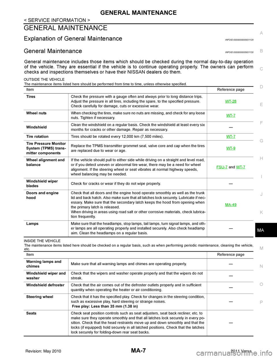
Explanation of Gene ral MaintenanceINFOID:0000000005931129
General MaintenanceINFOID:0000000005931130
General maintenance includes those items which shoul d be checked during the normal day-to-day operation
of the vehicle. They are essential if the vehicle is to continue operating properly. The owners can perform
checks and inspections themselves or have their NISSAN dealers do them.
OUTSIDE THE VEHICLE
The maintenance items listed here should be performed from time to time, unless otherwise specified.
INSIDE THE VEHICLE The maintenance items listed here should be checked on a regular basis, such as when performing periodic maintenance, cleaning the vehicle,
etc.
Item Reference page
Tires Check the pressure with a gauge often and always prior to long distance trips.
Adjust the pressure in all tires, including the spare, to the specified pressure.
Check carefully for damage, cuts or excessive wear. WT-28
Wheel nuts
When checking the tires, make sure no nuts are missing, and check for any loose
nuts. Tighten if necessary. WT-7
WindshieldClean the windshield on a regular basis. Check the windshield at least every six
months for cracks or other damage. Repair as necessary.
—
Tire rotation Tires should be rotated every 12,000 km (7,500 miles). WT-7
Tire Pressure Monitor
System (TPMS) trans-
mitter componentsReplace the TPMS transmitter grommet seal, valve core and cap when the tires
are replaced due to wear or age.
WT-9
Wheel alignment and
balanceIf the vehicle should pull to either side while driving on a straight and level road,
or if you detect uneven or abnormal tire wear, there may be a need for wheel
alignment. If the steering wheel or seat vibrates at normal highway speeds,
wheel balancing may be needed. FSU-7
and
WT-7
Windshield wiper
blades Check for cracks or wear if they do not wipe properly.
—
Doors and engine
hood Check that all doors and the engine hood operate smoothly as well as the trunk
lid and back hatch. Also make sure that all latches lock securely. Lubricate if nec-
essary. Make sure that the secondary latch keeps the hood from opening when
the primary latch is released.
When driving in areas using road salt or other corrosive materials, check lubrica-
tion frequently. MA-49
Lamps
Make sure that the headlamps, stop lamps, tail lamps, turn signal lamps, and oth-
er lamps are all operating properly and installed securely. Also check headlamp
aim. Clean the headlamps on a regular basis. —
Item
Reference page
Warning lamps and
chimes Make sure that all warning lamps and chimes are operating properly.
—
Windshield wiper and
washer Check that the wipers and washer operate properly and that the wipers do not
streak.
—
Windshield defroster Check that the air comes out of the defroster outlets properly and in sufficient
quantity when operating the heater or air conditioning. —
Steering wheel Check that it has the specified play. Check for changes in the steering condition,
such as excessive play, hard steering or strange noises.
Free play: Less than 35 mm (1.38 in) —
Seats Check seat position controls such as seat adjusters, seat back recliner, etc. to
make sure they operate smoothly and that all latches lock securely in every po-
sition. Check that the head restraints move up and down smoothly and that the
locks (if equipped) hold securely in all latched positions. Check that the latches
lock securely for folding-down rear seat backs. —
Revision: May 2010
2011 Versa
Page 3189 of 3787
MA-18
< SERVICE INFORMATION >
ENGINE MAINTENANCE (HR16DE)
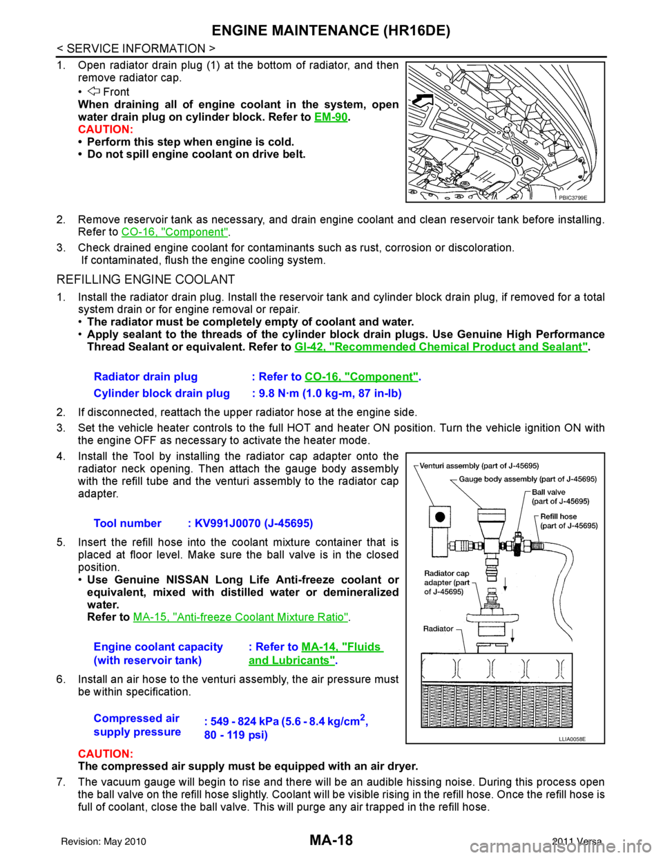
1. Open radiator drain plug (1) at the bottom of radiator, and thenremove radiator cap.
• Front
When draining all of engine coolant in the system, open
water drain plug on cylinder block. Refer to EM-90
.
CAUTION:
• Perform this step when engine is cold.
• Do not spill engine coolant on drive belt.
2. Remove reservoir tank as necessary, and drain engine coolant and clean reservoir tank before installing. Refer to CO-16, "
Component".
3. Check drained engine coolant for contaminants such as rust, corrosion or discoloration. If contaminated, flush the engine cooling system.
REFILLING ENGINE COOLANT
1. Install the radiator drain plug. Install the reservoir tank and cylinder block drain plug, if removed for a total
system drain or for engine removal or repair.
• The radiator must be complete ly empty of coolant and water.
• Apply sealant to the threads of the cylinder bl ock drain plugs. Use Genuine High Performance
Thread Sealant or equivalent. Refer to GI-42, "
Recommended Chemical Product and Sealant".
2. If disconnected, reattach the upper radiator hose at the engine side.
3. Set the vehicle heater controls to the full HOT and heat er ON position. Turn the vehicle ignition ON with
the engine OFF as necessary to activate the heater mode.
4. Install the Tool by installing the radiator cap adapter onto the radiator neck opening. Then attach the gauge body assembly
with the refill tube and the venturi assembly to the radiator cap
adapter.
5. Insert the refill hose into the coolant mixture container that is placed at floor level. Make sure the ball valve is in the closed
position.
•Use Genuine NISSAN Long Life Anti-freeze coolant or
equivalent, mixed with distil led water or demineralized
water.
Refer to MA-15, "
Anti-freeze Coolant Mixture Ratio".
6. Install an air hose to the venturi assembly, the air pressure must be within specification.
CAUTION:
The compressed air supply must be equipped with an air dryer.
7. The vacuum gauge will begin to rise and there will be an audible hissing noise. During this process open the ball valve on the refill hose slightly. Coolant will be vi sible rising in the refill hose. Once the refill hose is
full of coolant, close the ball valve. This will purge any air trapped in the refill hose.
PBIC3799E
Radiator drain plug : Refer to CO-16, "Component".
Cylinder block drain plug : 9.8 N·m (1.0 kg-m, 87 in-lb)
Tool number : KV991J0070 (J-45695)
Engine coolant capacity
(with reservoir tank) : Refer to
MA-14, "
Fluids
and Lubricants".
Compressed air
supply pressure : 549 - 824 kPa (5.6 - 8.4 kg/cm
2,
80 - 119 psi)
LLIA0058E
Revision: May 2010 2011 Versa
Page 3198 of 3787
ENGINE MAINTENANCE (MR18DE)MA-27
< SERVICE INFORMATION >
C
DE
F
G H
I
J
K
M A
B
MA
N
O P
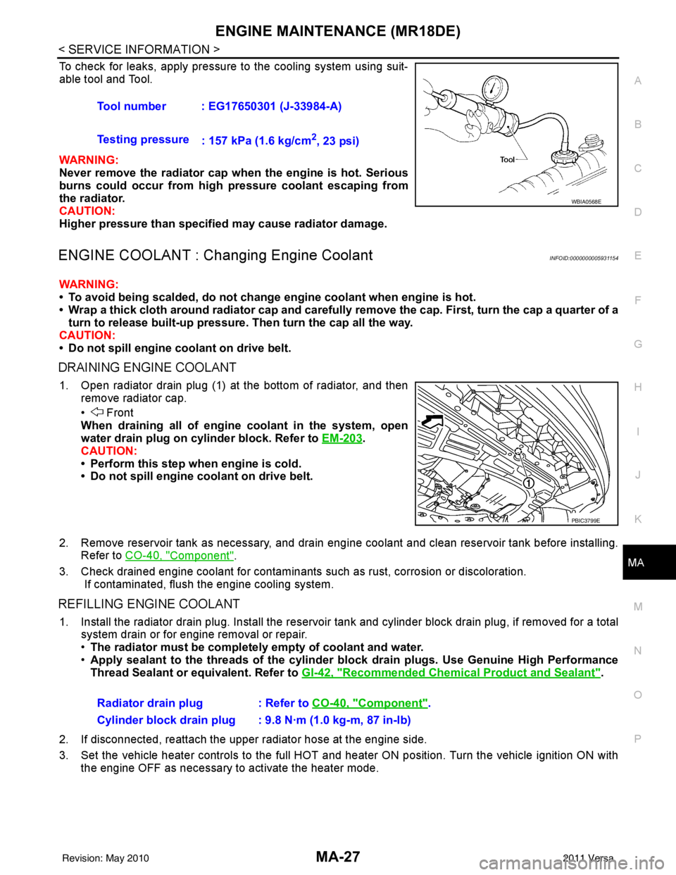
To check for leaks, apply pressure to the cooling system using suit-
able tool and Tool.
WARNING:
Never remove the radiator cap wh en the engine is hot. Serious
burns could occur from high pressure coolant escaping from
the radiator.
CAUTION:
Higher pressure than specified may cause radiator damage.
ENGINE COOLANT : Chang ing Engine CoolantINFOID:0000000005931154
WARNING:
• To avoid being scalded, do not change engine coolant when engine is hot.
• Wrap a thick cloth around radiator cap and carefully remove the cap. First, turn the cap a quarter of a
turn to release built-up pressure. Then turn the cap all the way.
CAUTION:
• Do not spill engine coolant on drive belt.
DRAINING ENGINE COOLANT
1. Open radiator drain plug (1) at the bottom of radiator, and then remove radiator cap.
• Front
When draining all of engine coolant in the system, open
water drain plug on cylinder block. Refer to EM-203
.
CAUTION:
• Perform this step when engine is cold.
• Do not spill engine coolant on drive belt.
2. Remove reservoir tank as necessary, and drain engi ne coolant and clean reservoir tank before installing.
Refer to CO-40, "
Component".
3. Check drained engine coolant for contaminants such as rust, corrosion or discoloration. If contaminated, flush the engine cooling system.
REFILLING ENGINE COOLANT
1. Install the radiator drain plug. Install the reservoir tank and cylinder block drain plug, if removed for a total
system drain or for engine removal or repair.
• The radiator must be completely empty of coolant and water.
• Apply sealant to the threads of the cylinder blo ck drain plugs. Use Genuine High Performance
Thread Sealant or equivalent. Refer to GI-42, "
Recommended Chemical Product and Sealant".
2. If disconnected, reattach the upper radiator hose at the engine side.
3. Set the vehicle heater controls to the full HOT and heat er ON position. Turn the vehicle ignition ON with
the engine OFF as necessary to activate the heater mode. Tool number : EG17650301 (J-33984-A)
Testing pressure
: 157 kPa (1.6 kg/cm
2, 23 psi)
WBIA0568E
PBIC3799E
Radiator drain plug : Refer to CO-40, "Component".
Cylinder block drain plug : 9.8 N·m (1.0 kg-m, 87 in-lb)
Revision: May 2010 2011 Versa
Page 3317 of 3787

MTC-1
AIR CONDITIONER
C
DE
F
G H
I
K L
M
SECTION MTC
A
B
MTC
N
O P
CONTENTS
MANUAL AIR CONDITIONER
SERVICE INFORMATION .. ..........................3
PRECAUTIONS .............................................. .....3
Precaution for Supplemental Restraint System
(SRS) "AIR BAG" and "SEAT BELT PRE-TEN-
SIONER" ............................................................. ......
3
Precaution Necessary for Steering Wheel Rota-
tion After Battery Disconnect ............................... ......
3
Precaution for Procedure without Cowl Top Cover ......4
Precaution for Working with HFC-134a (R-134a) ......4
General Refrigerant Precaution ................................4
Oil Precaution ............................................................5
Precaution for Refrigerant Connection ......................5
Precaution for Service of Compressor ................ ......8
Precaution for Service Equipment ....................... ......8
Precaution for Leak Detection Dye ...........................9
PREPARATION ..................................................11
HFC-134a (R-134a) Service Tool and Equipment ....11
Commercial Service Tool ........................................14
REFRIGERATION SYSTEM ..............................15
Refrigerant Cycle ................................................ ....15
Refrigerant System Protection ................................15
Component Part Location ................................... ....16
OIL ......................................................................17
Maintenance of Oil Quantity in Compressor ....... ....17
AIR CONDITIONER CONTROL .........................19
Control Operation ................................................ ....19
Discharge Air Flow ..................................................20
System Description .................................................20
TROUBLE DIAGNOSIS .....................................22
CONSULT-III Function (BCM) ............................. ....22
How to Perform Trouble Diagnosis for Quick and
Accurate Repair ......................................................
23
Component Parts and Harness Connector Loca-
tion ...................................................................... ....
23
Schematic ...............................................................26
Wiring Diagram - Heater - .......................................27
Wiring Diagram - A/C,M - .................................... ....28
Operational Check ...................................................31
Mode Door ...............................................................32
Air Mix Door .............................................................33
Intake Door ..............................................................34
Front Blower Motor Circuit .......................................34
Magnet Clutch Circuit (If Equipped) ..................... ....38
Insufficient Cooling ..................................................46
Insufficient Heating ..................................................53
Noise .......................................................................54
CONTROLLER ..................................................56
Removal and Installation .........................................56
Disassembly and Assembly .....................................57
THERMO CONTROL AMPLIFIER ....................58
Removal and Installation .........................................58
A/C UNIT ASSEMBLY ......................................59
Removal and Installation .........................................59
Disassembly and Assembly .....................................61
BLOWER MOTOR ............................................63
Removal and Installation .........................................63
INTAKE DOOR ..................................................64
Intake Door Cable Adjustment .................................64
AIR MIX DOOR .................................................65
Air Mix Door Cable Adjustment ...............................65
MODE DOOR ....................................................66
Mode Door Cable Adjustment .................................66
BLOWER FAN RESISTOR ...............................67
Removal and Installation .........................................67
HEATER CORE .................................................68
Removal and Installation .........................................68
DUCTS AND GRILLES .....................................69
Removal and Installation .........................................69
Revision: May 2010 2011 Versa
Page 3343 of 3787
TROUBLE DIAGNOSISMTC-27
< SERVICE INFORMATION >
C
DE
F
G H
I
K L
M A
B
MTC
N
O P
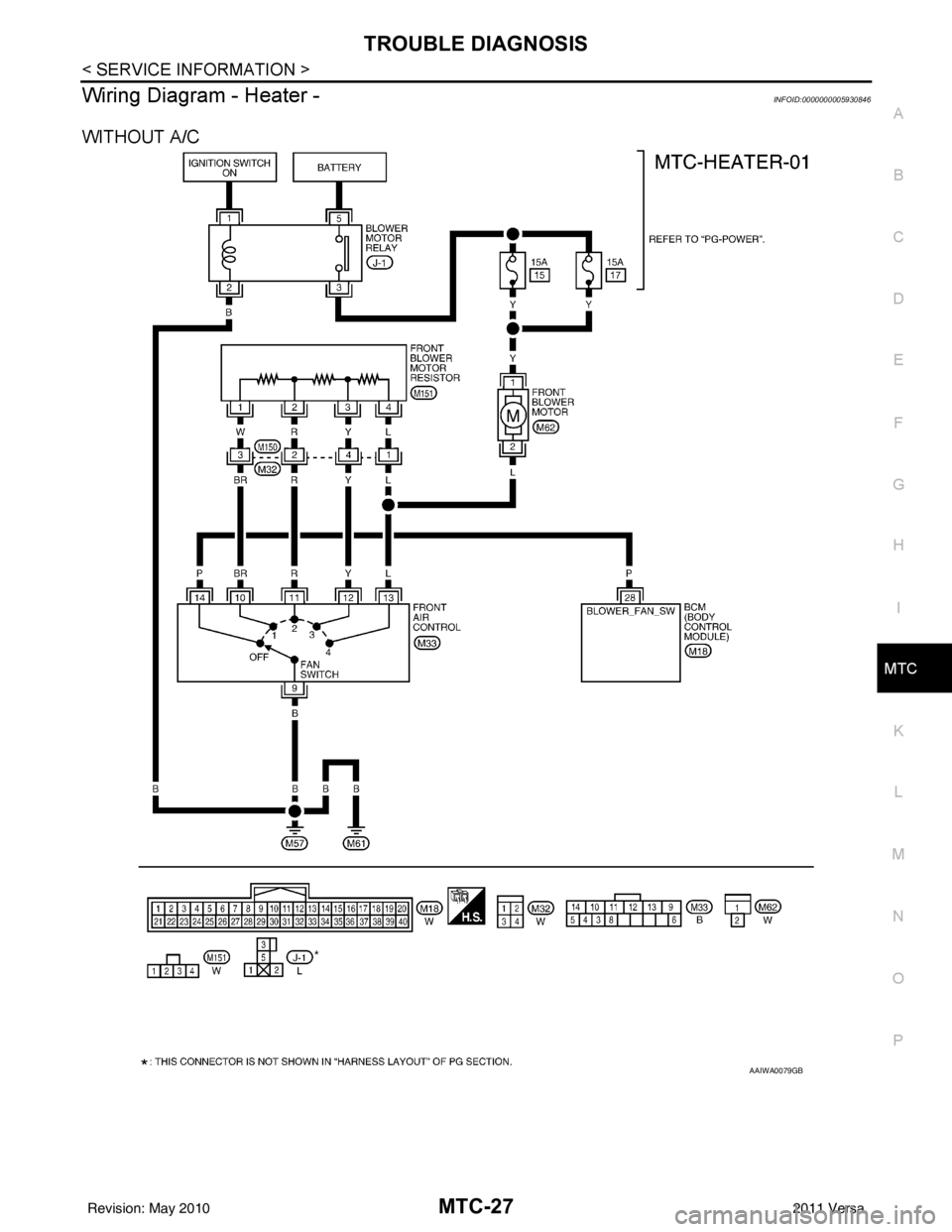
Wiring Diagram - Heater -INFOID:0000000005930846
WITHOUT A/C
AAIWA0079GB
Revision: May 2010 2011 Versa
Page 3370 of 3787
MTC-54
< SERVICE INFORMATION >
TROUBLE DIAGNOSIS
YES >> GO TO 6.
NO >> Adjust or replace air mix door cable. Refer to MTC-65, "
Air Mix Door Cable Adjustment" .
6.CHECK AIR DUCTS
Check ducts for air leaks.
OK or NG
OK >> GO TO 7.
NG >> Repair air leaks.
7.CHECK HEATER HOSE TEMPERATURES
1. Start engine and warm it up to normal operating temperature.
2. Touch both the inlet and outlet heater hoses. The inlet hose should be hot and the outlet hose should be
warm.
Is the inlet hose hot and the outlet hose warm?
YES >> GO TO 8.
NO >> Both hoses warm: GO TO 9.
8.CHECK ENGINE COOLANT TEMPERATURE SENSOR
Check engine control temperature sensor. Refer to EC-172, "
Component Inspection" (MR18DE) or EC-690,
"Component Inspection" (HR16DE).
OK or NG
OK >> System OK.
NG >> Repair or replace as necessary. Retest.
9.CHECK HEATER HOSES
Check heater hoses for proper installation.
OK or NG
OK >> GO TO 10.
NG >> Repair /replace as necessary. Retest GO TO 7.
10.BACK FLUSH HEATER CORE
1. Back flush heater core.
2. Drain the water from the system.
3. Refill system with new engine coolant. Refer to CO-11, "
Changing Engine Coolant" (HR16DE) or CO-36,
"Changing Engine Coolant" (MR18DE) .
4. Start engine and warm it up to normal operating temperature.
5. Touch both the inlet and outlet heater hoses. The inlet hose should be hot and the outlet hose should be
warm.
Is the inlet hose hot and the outlet hose warm?
YES >> System OK.
NO >> Replace heater core and refill engine coolant. Refer to MTC-68, "
Removal and Installation" .
NoiseINFOID:0000000005930856
SYMPTOM: Noise
INSPECTION FLOW
Revision: May 2010 2011 Versa