2011 NISSAN TIIDA body control
[x] Cancel search: body controlPage 2267 of 3787
![NISSAN TIIDA 2011 Service Repair Manual DTC P2127, P2128 APP SENSOREC-973
< SERVICE INFORMATION > [MR18DE]
C
D
E
F
G H
I
J
K L
M A
EC
NP
O
Diagnosis ProcedureINFOID:0000000006342193
1.CHECK GROUND CONNECTIONS
1. Turn ignition switch OFF.
2. NISSAN TIIDA 2011 Service Repair Manual DTC P2127, P2128 APP SENSOREC-973
< SERVICE INFORMATION > [MR18DE]
C
D
E
F
G H
I
J
K L
M A
EC
NP
O
Diagnosis ProcedureINFOID:0000000006342193
1.CHECK GROUND CONNECTIONS
1. Turn ignition switch OFF.
2.](/manual-img/5/57396/w960_57396-2266.png)
DTC P2127, P2128 APP SENSOREC-973
< SERVICE INFORMATION > [MR18DE]
C
D
E
F
G H
I
J
K L
M A
EC
NP
O
Diagnosis ProcedureINFOID:0000000006342193
1.CHECK GROUND CONNECTIONS
1. Turn ignition switch OFF.
2. Loosen and retighten ground screws on the body. Refer to EC-638, "
Ground Inspection".
TER-
MI-
NAL
NO. WIRE
COLOR ITEM
CONDITION DATA (DC Voltage)
74 W Sensor power supply
(Refrigerant pressure sen-
sor)
[Ignition switch: ON]
Approximately 5 V
75 BR Sensor power supply
[Crankshaft position sensor
(POS)] [Ignition switch: ON]
Approximately 5 V
76 W EVAP control system pres-
sure sensor power supply [Ignition switch: ON]
Approximately 5 V
102 SB Sensor power supply
(APP sensor 2)
[Ignition switch: ON]
Approximately 5 V
103 GR Accelerator pe
dal position
sensor 2 [Ignition switch: ON]
• Engine stopped
• Accelerator pedal: Fully released
0.3 - 0.6 V
[Ignition switch: ON]
• Engine stopped
• Accelerator pedal: Fully depressed 1.95 - 2.4 V
104 Y Sensor ground
(APP sensor 2) [Engine is running]
•
Warm-up condition
• Idle speed Approximately 0 V
106 P Sensor power supply
(APP sensor 1) [Ignition switch: ON]
Approximately 5 V
11 0 G Accelerator pe
dal position
sensor 1 [Ignition switch: ON]
• Engine stopped
• Accelerator pedal: Fully released
0.6 - 0.9 V
[Ignition switch: ON]
• Engine stopped
• Accelerator pedal: Fully depressed 3.9 - 4.7 V
111 R Sensor ground
(APP sensor 1) [Engine is running]
•
Warm-up condition
• Idle speed Approximately 0 V
:
Vehicle front
1. Body ground E24 2. Engine ground F93. Engine ground F16
4. Body ground E15
BBIA0698E
Revision: May 2010 2011 Versa
Page 2279 of 3787
![NISSAN TIIDA 2011 Service Repair Manual DTC P2138 APP SENSOREC-985
< SERVICE INFORMATION > [MR18DE]
C
D
E
F
G H
I
J
K L
M A
EC
NP
O
Diagnosis ProcedureINFOID:0000000006342209
1.CHECK GROUND CONNECTIONS
1. Turn ignition switch OFF.
2. Loosen NISSAN TIIDA 2011 Service Repair Manual DTC P2138 APP SENSOREC-985
< SERVICE INFORMATION > [MR18DE]
C
D
E
F
G H
I
J
K L
M A
EC
NP
O
Diagnosis ProcedureINFOID:0000000006342209
1.CHECK GROUND CONNECTIONS
1. Turn ignition switch OFF.
2. Loosen](/manual-img/5/57396/w960_57396-2278.png)
DTC P2138 APP SENSOREC-985
< SERVICE INFORMATION > [MR18DE]
C
D
E
F
G H
I
J
K L
M A
EC
NP
O
Diagnosis ProcedureINFOID:0000000006342209
1.CHECK GROUND CONNECTIONS
1. Turn ignition switch OFF.
2. Loosen and retighten ground screws on the body. Refer to EC-638, "
Ground Inspection".
TER-
MI-
NAL
NO. WIRE
COLOR ITEM
CONDITION DATA (DC Voltage)
74 W Sensor power supply
(Refrigerant pressure sen-
sor)
[Ignition switch: ON]
Approximately 5 V
75 BR Sensor power supply
[Crankshaft position sensor
(POS)] [Ignition switch: ON]
Approximately 5 V
76 W EVAP control system pres-
sure sensor power supply [Ignition switch: ON]
Approximately 5 V
102 SB Sensor power supply
(APP sensor 2)
[Ignition switch: ON]
Approximately 5 V
103 GR Accelerator pe
dal position
sensor 2 [Ignition switch: ON]
• Engine stopped
• Accelerator pedal: Fully released
0.3 - 0.6 V
[Ignition switch: ON]
• Engine stopped
• Accelerator pedal: Fully depressed 1.95 - 2.4 V
104 Y Sensor ground
(APP sensor 2) [Engine is running]
•
Warm-up condition
• Idle speed Approximately 0 V
106 P Sensor power supply
(APP sensor 1) [Ignition switch: ON]
Approximately 5 V
11 0 G Accelerator pe
dal position
sensor 1 [Ignition switch: ON]
• Engine stopped
• Accelerator pedal: Fully released
0.6 - 0.9 V
[Ignition switch: ON]
• Engine stopped
• Accelerator pedal: Fully depressed 3.9 - 4.7 V
111 R Sensor ground
(APP sensor 1) [Engine is running]
•
Warm-up condition
• Idle speed Approximately 0 V
:
Vehicle front
1. Body ground E24 2. Engine ground F9 3. Engine ground F16
4. Body ground E15
BBIA0698E
Revision: May 2010 2011 Versa
Page 2473 of 3787
![NISSAN TIIDA 2011 Service Repair Manual ENGINE ASSEMBLYEM-83
< REMOVAL AND INSTALLATION > [HR16DE]
C
D
E
F
G H
I
J
K L
M A
EM
NP
O
• If items or work required are not covered by the engine section, follow the procedures in the applica-
bl NISSAN TIIDA 2011 Service Repair Manual ENGINE ASSEMBLYEM-83
< REMOVAL AND INSTALLATION > [HR16DE]
C
D
E
F
G H
I
J
K L
M A
EM
NP
O
• If items or work required are not covered by the engine section, follow the procedures in the applica-
bl](/manual-img/5/57396/w960_57396-2472.png)
ENGINE ASSEMBLYEM-83
< REMOVAL AND INSTALLATION > [HR16DE]
C
D
E
F
G H
I
J
K L
M A
EM
NP
O
• If items or work required are not covered by the engine section, follow the procedures in the applica-
ble sections.
• Always use the support poin t specified for lifting.
• Use either 2-pole lift type or separate type lift as best you can. If board-on type is used for unavoid-
able reasons, support at the rear axle jacking point with a transmission jack or similar tool before
starting work, in preparation for the backward shif t of center of gravity.
• For supporting points fo r lifting and jacking point at rear axle, refer to GI-38, "
Garage Jack and
Safety Stand and 2-Pole Lift".
REMOVAL
Outline
Remove the engine and the transaxle assembly from t he vehicle downward. Separate the engine and the tran-
saxle.
Preparation
1. Remove the hood assembly. Refer to BL-14, "Removal and Installation".
2. Remove the cowl top cover and cowl top extension assembly. Refer to EI-24, "
Removal and Installation".
3. Release fuel pressure. Refer to EC-499, "
Inspection".
4. Drain engine coolant from radiator. Refer to CO-11, "
Changing Engine Coolant".
CAUTION:
• Perform this step when the engine is cold.
• Never spill engine coolant on drive belt.
5. Remove the following parts. • Engine under cover. Refer to EI-15, "
Removal and Installation".
• Front road wheels and tires. Refer to WT-7, "
Adjustment".
• Front fender protector (RH and LH). Refer to EI-26, "
Removal and Installation".
• Battery and battery tray. Refer to SC-7, "
Removal and Installation".
• Drive belt. Refer to EM-14, "
Removal and Installation".
• Air duct and air cleaner case assembly. Refer to EM-25, "
Exploded View".
• Radiator hose (upper and lower). Refer to CO-16, "
Component".
• Disconnect cooling fan controller wiring harness.
• Remove coolant reservoir tank.
• Remove fan shroud and cooling fan assembly. Refer to CO-18, "
Component (Models with A/C)" or CO-
18, "Component (Models without A/C)".
Engine Room LH
1. Disconnect all connections of engine harness around the engine mounting insulator (LH), and then tem-
porarily secure the engine harness into the engine side.
CAUTION:
Protect connectors using a resin bag against foreign materials.
2. Remove ground cable at transaxle side.
3. Disconnect fuel feed hose at engine side. Refer to EM-33, "
Exploded View".
4. Disconnect EVAP purge hose and brake booster vacuum hose.
5. Disconnect heater hoses, and install plugs them to prevent engine coolant from draining. Refer to CO-16,
"Component".
6. Disconnect control linkage from transaxle. Refer to AT-213, "
A/T Shift Selector Removal and Installation"
(A/T), MT-14, "Exploded View" (M/T).
7. Disconnect the clutch tube at tr ansmission side (if equipped). Refer to CL-15, "
Removal and Installation".
Engine Room RH
1. Remove ground cable between front cover and vehicle.
2. Remove generator and generator br acket (A/C models). Refer to SC-25, "
Removal and Installation".
3. Remove A/C compressor with piping connected from t he engine. Temporarily secure it on the vehicle side
with a rope to avoid putting load on it (if equipped). Refer to MTC-78, "
Removal and Installation of Com-
pressor - HR16DE".
Vehicle Underbody
1. Remove front wheel sensor (LH and RH) for ABS from steering knuckle (if equipped). Refer to BRC-33,
"Removal and Installation" (ABS) or BRC-86, "Removal and Installation" (VDC/TCS/ABS).
Revision: May 2010 2011 Versa
Page 2736 of 3787

GI-32
< SERVICE INFORMATION >
SERVICE INFORMATION FOR ELECTRICAL INCIDENT
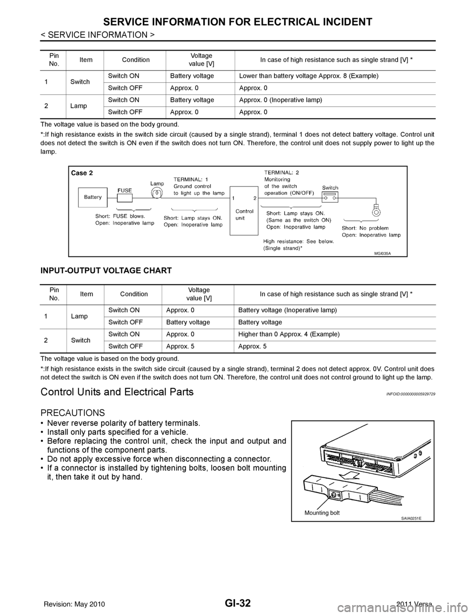
The voltage value is based on the body ground.
*:If high resistance exists in the switch side circuit (caused by a single strand), terminal 1 does not detect battery voltage. Control unit
does not detect the switch is ON even if the switch does not turn ON. Therefore, the control unit does not supply power to ligh t up the
lamp.
INPUT-OUTPUT VOLTAGE CHART
The voltage value is based on the body ground.
*:If high resistance exists in the switch side circuit (caused by a single strand), terminal 2 does not detect approx. 0V. Cont rol unit does
not detect the switch is ON even if the switch does not turn ON. Therefore, the control unit does not control ground to light u p the lamp.
Control Units and Electrical PartsINFOID:0000000005929729
PRECAUTIONS
• Never reverse polarity of battery terminals.
• Install only parts specified for a vehicle.
• Before replacing the control unit, check the input and output and
functions of the component parts.
• Do not apply excessive force when disconnecting a connector.
• If a connector is installed by tightening bolts, loosen bolt mounting
it, then take it out by hand.
Pin
No. Item Condition
Vo l ta g e
value [V] In case of high resistance such as single strand [V] *
1Switch Switch ON Battery voltage Lower than battery voltage Approx. 8 (Example)
Switch OFF Approx. 0
Approx. 0
2Lamp Switch ON Battery voltage App
rox. 0 (Inoperative lamp)
Switch OFF Approx. 0 Approx. 0
MGI035A
Pin
No. Item Condition
Vo l ta g e
value [V] In case of high resistance such as single strand [V] *
1Lamp Switch ON Approx. 0
Battery voltage (Inoperative lamp)
Switch OFF Battery voltage Battery voltage
2Switch Switch ON Approx. 0
Higher than 0 Approx. 4 (Example)
Switch OFF Approx. 5 Approx. 5
SAIA0251E
Revision: May 2010 2011 Versa
Page 2748 of 3787

GI-44
< SERVICE INFORMATION >
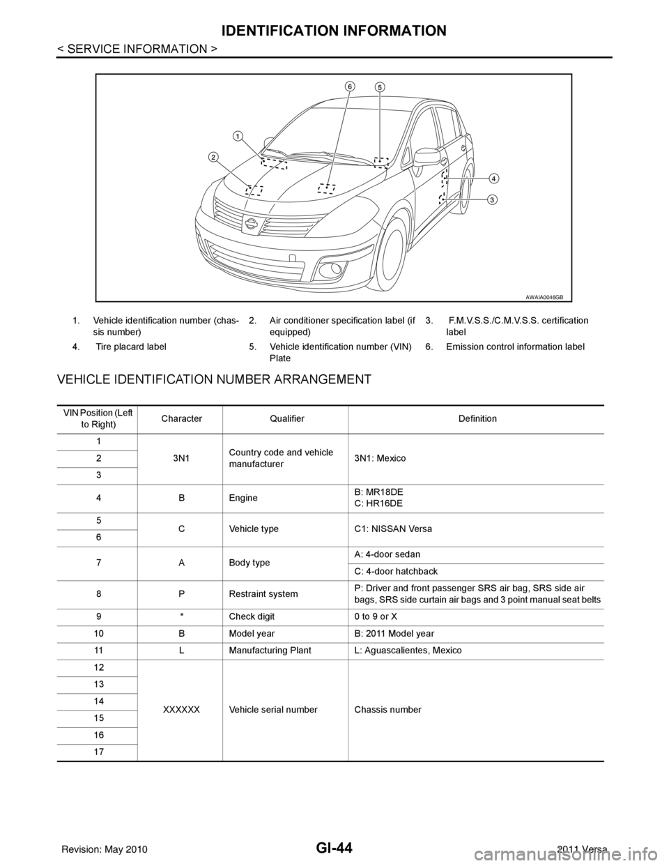
IDENTIFICATION INFORMATION
VEHICLE IDENTIFICATION NUMBER ARRANGEMENT
1. Vehicle identification number (chas-
sis number) 2. Air conditioner specification label (if
equipped) 3. F.M.V.S.S./C.M.V.S.S. certification
label
4. Tire placard label 5. Vehicle identification number (VIN)
Plate 6. Emission control information label
AWAIA0046GB
VIN Position (Left
to Right) Character
Qualifier Definition
1 3N1Country code and vehicle
manufacturer
3N1: Mexico
2
3
4 B Engine B: MR18DE
C: HR16DE
5 C Vehicle type C1: NISSAN Versa
6
7 A Body type A: 4-door sedan
C: 4-door hatchback
8 P Restraint system P: Driver and front passenger SRS air bag, SRS side air
bags, SRS side curtain air bags and 3 point manual seat belts
9 * Check digit 0 to 9 or X
10 B Model year B: 2011 Model year
11 L Manufacturing Plant L: Aguascalientes, Mexico
12
XXXXXX Vehicle serial number Chassis number
13
14
15
16
17
Revision: May 2010
2011 Versa
Page 2753 of 3787

TERMINOLOGYGI-49
< SERVICE INFORMATION >
C
DE
F
G H
I
J
K L
M B
GI
N
O P
Nonvolatile random access memory NVRAM ***
On board diagnostic system OBD system Self-diagnosis
Open loop OLOpen loop
Oxidation catalyst OCCatalyst
Oxidation catalytic converter system OC system ***
Oxygen sensor O2S Exhaust gas sensor
Park position switch ***Park switch
Park/neutral position switch PNP switchPark/neutral switch
Inhibitor switch
Neutral position switch
Periodic trap oxidizer system PTOX system ***
Positive crankcase ventilation PCV Positive crankcase ventilation
Positive crankcase ventilation valve PCV valve PCV valve
Powertrain cont rol module PCM ***
Programmable read only memory PROM***
Pulsed secondary air injection control sole-
noid valve PAIRC solenoid valve
AIV control solenoid valve
Pulsed secondary air injection system PAIR system Air induction valve (AIV) control
Pulsed secondary air injection valve PAIR valve Air induction valve
Random access memory RAM***
Read only memory ROM***
Scan tool ST ***
Secondary air injection pump AIR pump ***
Secondary air injection system AIR system ***
Sequential multiport fuel injection system SFI system Sequential fuel injection
Service reminder indicator SRI***
Simultaneous multiport fuel injection sys-
tem ***
Simultaneous fuel injection
Smoke puff limiter system SPL system***
Supercharger SC ***
Supercharger bypass SCB ***
System readiness test SRT***
Thermal vacuum valve TVV Thermal vacuum valve
Three way catalyst TWC Catalyst
Three way catalytic converter system TWC system ***
Three way + oxidation catalyst TWC + OC Catalyst
Three way + oxidation catalytic converter
system TWC + OC system
***
Throttle body TBThrottle chamber
SPI body
Throttle body fuel injection system TBI system Fuel injection control
Throttle position TP Throttle position
Throttle position sensor TPS Throttle sensor
Throttle position switch TP switchThrottle switch
Torque converter clutch solenoid valve TCC solenoid valve Lock-up cancel solenoid
Lock-up solenoid
NEW TERM
NEW ACRONYM /
ABBREVIATION OLD TERM
Revision: May 2010
2011 Versa
Page 2785 of 3787

POWER WINDOW SYSTEMGW-31
< SERVICE INFORMATION >
C
DE
F
G H
J
K L
M A
B
GW
N
O P
WORK SUPPORT
DATA MONITOR
Power Window Auto Operation InitializationINFOID:0000000005929478
1. Turn the ignition switch ON.
2. Open the window—all the way DOWN.
3. Pull all the way UP on the switch and hold (close the window). • Continue holding the switch all the way UP for 4 seconds after the window is closed.
4. Confirm the window is now operating correctly. NOTE:
• If the window is still not operating correctly, refer to GW-31, "
Trouble Diagnosis Symptom Chart".
• The above initialization procedure must be performed if any of the following occur:
- Battery cable is disconnected
- Power window switch connector is disconnected
- Power window regulator is replaced
- Power window motor is replaced
- Window glass is removed
- Window glass run rubber is replaced
- Power window fuse is blown
- Window is partly opened and/or closed many times without being fully closed.
Trouble Diagnosis Symptom ChartINFOID:0000000005929479
Check that other systems us ing the signal of the following systems operate normally.
Test Item Description
RETAINED PWR This test is able to supply RAP signal (powe
r) from BCM (body control module) to power window
system and power sunroof system (if equipped). Those systems can be operated when turning on
“RETAINED PWR” on CONSULT-III screen even if the ignition switch is turned OFF.
NOTE:
During this test, CONSULT-III can be operated with ignition switch in OFF position. “RETAINED
PWR” should be turned “ON” or “OFF” on CONSULT-III screen when ignition switch is ON. Then
turn ignition switch OFF to check retained power operation. CONSULT-III might be stuck if “RE-
TAINED PWR” is turned “ON” or “OFF” on CONSULT-III screen when ignition switch is OFF.
Work item Description
RETAINED PWR RAP signal’s power supply period can be changed by mode setting. Selects RAP signal’s power
supply period between three steps
• MODE1 (45 sec.)/MODE2 (OFF)/MODE3 (2 min.).
Work item
Description
IGN ON SW Indicates (ON/OFF) condition of ignition switch
DOOR SW-DR Indicates (ON/OFF) condition of front door switch LH
DOOR SW-AS Indicates (ON/OFF) condition of front door switch RH
Symptom Repair orderRefer to page
None of the power windows can be operated using any switch 1. BCM power supply and ground circuit check
BCS-16
2. Main power window and door lock/unlock
power supply and ground circuit check GW-32
3. Replace main power window and door lock/
unlock switch
EI-36
Front power window LH alone does not operate 1. Front power window motor LH circuit check
GW-332. Replace main power window and door lock/
unlock switch EI-36
Revision: May 2010
2011 Versa
Page 2805 of 3787

REAR WINDOW DEFOGGERGW-51
< SERVICE INFORMATION >
C
DE
F
G H
J
K L
M A
B
GW
N
O P
REAR WINDOW DEFOGGER
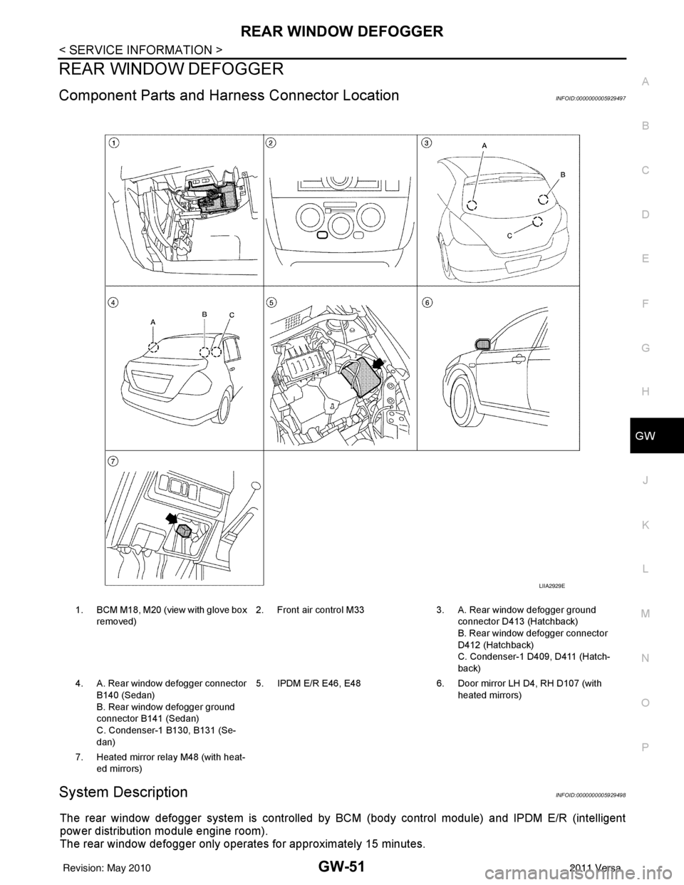
Component Parts and Har ness Connector LocationINFOID:0000000005929497
System DescriptionINFOID:0000000005929498
The rear window defogger system is controlled by BCM (body control module) and IPDM E/R (intelligent
power distribution module engine room).
The rear window defogger only operates for approximately 15 minutes.
1. BCM M18, M20 (view with glove box
removed) 2. Front air control M33 3. A. Rear window defogger ground
connector D413 (Hatchback)
B. Rear window defogger connector
D412 (Hatchback)
C. Condenser-1 D409, D411 (Hatch-
back)
4. A. Rear window defogger connector B140 (Sedan)
B. Rear window defogger ground
connector B141 (Sedan)
C. Condenser-1 B130, B131 (Se-
dan) 5. IPDM E/R E46, E48
6. Door mirror LH D4, RH D107 (with
heated mirrors)
7. Heated mirror relay M48 (with heat- ed mirrors)
LIIA2929E
Revision: May 2010 2011 Versa