2011 NISSAN NOTE tow
[x] Cancel search: towPage 9 of 235

FRONT
1.Bonnet (P. 3-10)
2.Windscreen (Wiper and washer switch
P. 2-13, Wiper replacement P. 8-19, Washer
fluid P. 8-14)
3.Power windows (P. 2-25)
4.Headlights, front side lights, turn signal lights
(Switch P. 2-16, Location and bulb replace-
ment P. 8-23)
5.Towing eye (P. 6-13)
6.Tyres (Tyres and wheels P. 8-29, 9-5, Flat tyre
P. 6-3)
7.Side turn signal light (P. 2-17, Location and
bulb replacement P. 8-23)
8.Outside rear view mirrors (P. 3-12)
9.Doors (Keys P. 3-2, Door locks P. 3-6,
Remote keyless entry system P. 3-3)
REAR
1.Rear window (Defogger switch P. 2-15)
2.High mounted stop light (P. 8-23)
3.Antenna (P. 4-16)
4.Rear combination light (Switch P. 2-16, Loca-
tion and bulb replacement P. 8-23)
5.Back door handle (Door locks P. 3-8, Remote
keyless entry system P. 3-3)
6.Rear wiper (Wiper and washer switch P. 2-13,
Wiper replacement P. 8-19)
7.Ultrasonic parking sensors (P. 3-22)
8.Fuel filler lid (P. 3-11)
NIC1104ZNIC1475
EXTERIOR FRONT AND REAR
Illustrated table of contents0-3
Page 21 of 235

secured in the latched position. If they are not
completely secured, passengers may be in-
jured in an accident or sudden stop.
•Closely supervise children when they are
around the vehicle to prevent them from play-
ing and being locked in the luggage compart-
ment where they could be seriously injured.
Keep the vehicle locked with the rear seat-
back securely latched when not in use, and
prevent children from having access to the
vehicle’s keys.
•Head restraints should be adjusted properly
as they may provide significant protection
against whiplash injury. Always adjust them
properly when returning the seatbacks to the
upright position.
NOTE
The lowest head restraint position is a stowage
position to assist seat folding and rear vision.
The lowest position intended for use is with the
head restraint raised to its first notch position. It
should be further adjusted to suit the passenger
if necessary.
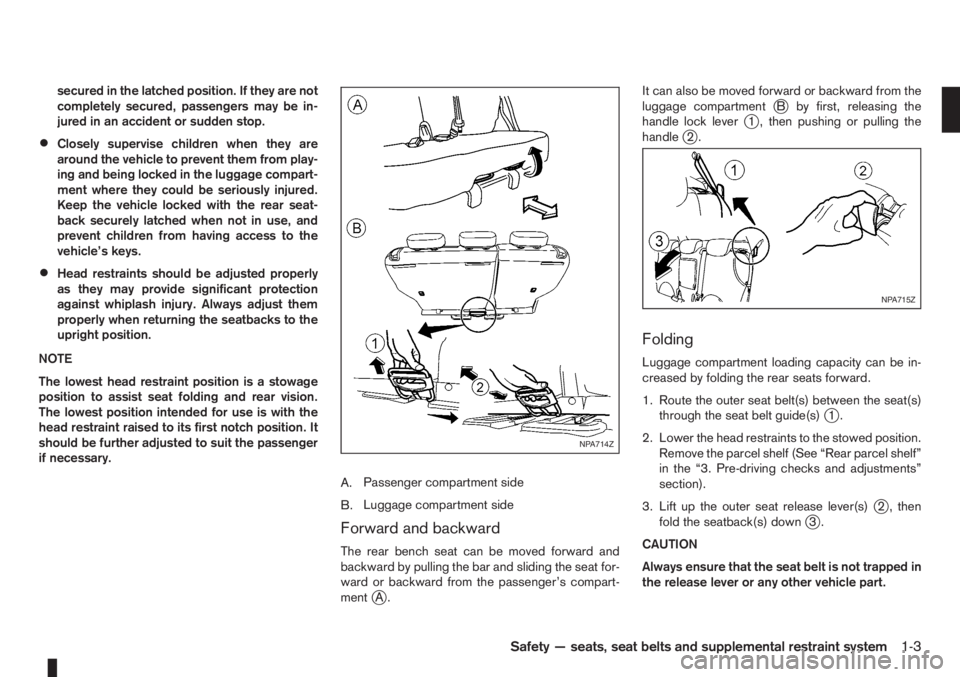
A.Passenger compartment side
B.Luggage compartment side
Forward and backward
The rear bench seat can be moved forward and
backward by pulling the bar and sliding the seat for-
ward or backward from the passenger’s compart-
ment
jA.It can also be moved forward or backward from the
luggage compartment
jB by first, releasing the
handle lock leverj1 , then pushing or pulling the
handlej2.
Folding
Luggage compartment loading capacity can be in-
creased by folding the rear seats forward.
1. Route the outer seat belt(s) between the seat(s)
through the seat belt guide(s)
j1.
2. Lower the head restraints to the stowed position.
Remove the parcel shelf (See “Rear parcel shelf”
in the “3. Pre-driving checks and adjustments”
section).
3. Lift up the outer seat release lever(s)
j2 , then
fold the seatback(s) downj3.
CAUTION
Always ensure that the seat belt is not trapped in
the release lever or any other vehicle part.
NPA714Z
NPA715Z
Safety — seats, seat belts and supplemental restraint system1-3
Page 22 of 235

Armrests (where fitted)
Driver and front passenger seat armrests:
WARNING
Do not adjust the driver’s seat armrest while driv-
ing so that full attention may be given to the ve-
hicle handling.
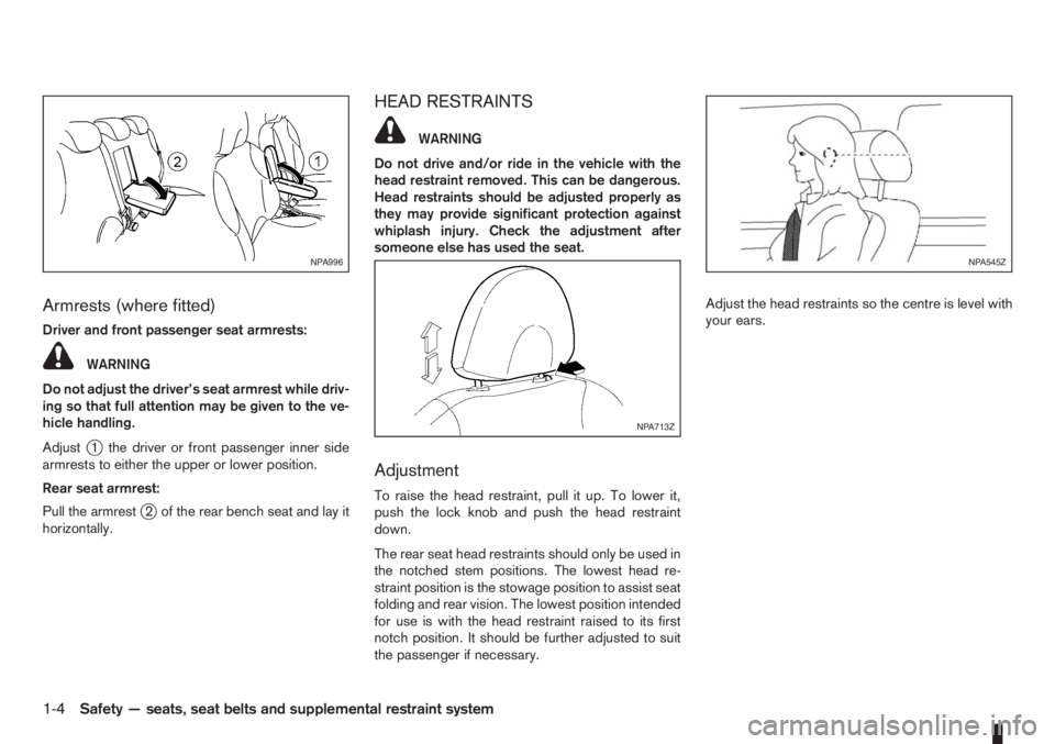
Adjust
j1 the driver or front passenger inner side
armrests to either the upper or lower position.
Rear seat armrest:
Pull the armrest
j2 of the rear bench seat and lay it
horizontally.
HEAD RESTRAINTS
WARNING
Do not drive and/or ride in the vehicle with the
head restraint removed. This can be dangerous.
Head restraints should be adjusted properly as
they may provide significant protection against
whiplash injury. Check the adjustment after
someone else has used the seat.
Adjustment
To raise the head restraint, pull it up. To lower it,
push the lock knob and push the head restraint
down.
The rear seat head restraints should only be used in
the notched stem positions. The lowest head re-
straint position is the stowage position to assist seat
folding and rear vision. The lowest position intended
for use is with the head restraint raised to its first
notch position. It should be further adjusted to suit
the passenger if necessary.Adjust the head restraints so the centre is level with
your ears.
NPA996
NPA713Z
NPA545Z
1-4Safety — seats, seat belts and supplemental restraint system
Page 26 of 235

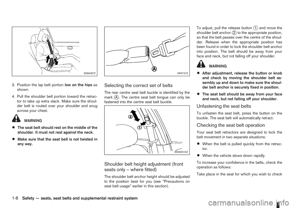
3. Position the lap belt portionlow on the hipsas
shown.
4. Pull the shoulder belt portion toward the retrac-
tor to take up extra slack. Make sure the shoul-
der belt is routed over your shoulder and snug
across your chest.
WARNING
•The seat belt should rest on the middle of the
shoulder. It must not rest against the neck.
•Make sure that the seat belt is not twisted in
any way.
Selecting the correct set of belts
The rear centre seat belt buckle is identified by the
markjA . The centre seat belt tongue can only be
fastened into the centre seat belt buckle.
Shoulder belt height adjustment (front
seats only – where fitted)
The shoulder belt anchor height should be adjusted
to the position best for you (see “Precautions on
seat belt usage” earlier in this section).To adjust, pull the release button
j1 and move the
shoulder belt anchorj2 to the appropriate position,
so that the belt passes over the centre of the shoul-
der. Release when the appropriate position has
been found in order to lock the shoulder belt anchor
into position. The belt should be away from your
face and neck, but not falling off your shoulder.
WARNING
•After adjustment, release the button or knob
and check by moving the shoulder belt as-
sembly up and down to make sure the shoul-
der belt anchor is securely fixed in position.
•The seat belt should be away from your face
and neck, but not falling off your shoulder.
Unfastening the seat belts
To unfasten the seat belt, press the button on the
buckle. The seat belt will automatically retract.
Checking the seat belt operation
Your seat belt retractors are designed to lock the
belt movement in two separate situations:
•When the belt is pulled quickly from the retrac-
tor.
•When the vehicle slows down rapidly.
To increase your confidence in the belts, check the
operation as follows:
Take place in the seat for which you wish to check
SSS0467ZNPA747Z
SSS0351AZ
1-8Safety — seats, seat belts and supplemental restraint system
Page 50 of 235

“Supplemental Restraint System (air bag system)”
in the “1. Safety — seats, seat belts and supple-
mental restraint system” section.
Brake warning light
This light functions for both the handbrake and the
footbrake systems.
Handbrake indicator:
The light comes on when the handbrake is applied.
Low brake fluid warning:
The light warns of a low brake fluid level in the brake
power assist unit. If the light comes on while the
engine is running and the handbrake is not applied,
stop the vehicle and perform the following:
1. Check the brake fluid level. Add brake fluid as
much as necessary. See “Brake and clutch fluid”
in the “8. Maintenance and do-it-yourself” sec-
tion.
WARNING
If the level is below the MIN mark on the brake
fluid reservoir, do not drive until the brake sys-
tem has been checked at a NISSAN dealer or
qualified workshop.
2. If the brake fluid level is correct:
Have the warning system checked by a NISSAN
dealer or qualified workshop.
WARNING
•Driving your vehicle could be dangerous.
Therefore have it towed to the nearest
NISSAN dealer or qualified workshop.
•Pressing the brake pedal with the engine
stopped and/or low brake fluid level could in-
crease your stopping distance and require
greater pedal effort as well as pedal travel.
Charge warning light
If the light comes on while the engine is running, it
may indicate that the charging system is malfunc-
tioning. Turn the engine off and check the alternator
belt. If the belt is loose, broken, missing or if the light
remains on, see a NISSAN dealer or qualified work-
shop immediately.
CAUTION
Do not continue driving if the belt is loose, bro-
ken or missing.
Door open warning light
This light comes on when any of the doors are not
closed securely while the ignition switch is in the
ON position.
Engine coolant temperature
warning light
The engine coolant temperature varies with the out-
side air temperature and driving condition.
When the ignition switch is turned to the ON posi-tion, the engine coolant temperature warning light
illuminates for a few seconds and then goes off.
This means the system is operational.
The engine coolant temperature warning light illumi-
nates when the engine coolant temperature reaches
an excessively high temperature of approximately
105 °C (221 °F).
CAUTION
•If the engine coolant temperature warning
light comes on, stop the vehicle as soon as
safely possible and contact a NISSAN dealer
or qualified workshop.
•When towing a trailer or driving uphill, reduce
the vehicle speed as soon as safely possible
to decrease the engine coolant temperature.
•If the engine overheats, continued operation
of the vehicle may seriously damage the en-
gine. See “Engine overheat” in the “6. In case
of emergency” section for immediate action
required.
WARNING
Do not remove the radiator cap while the engine
is hot. Otherwise, there is a danger of being
scalded by the coolant that is likely to erupt from
the filler.
Engine oil pressure warning light
This light warns of low engine oil pressure. If the
light flickers, comes on during normal driving, or
stays on once the engine is started, pull off the road
2-8Instruments and controls
Page 51 of 235

in a safe area, stop the engineimmediatelyand call
a NISSAN dealer or qualified workshop.
CAUTION
•Running the engine with the engine oil pres-
sure warning light on could cause serious
damage to the engine.
•The engine oil pressure warning light is not
designed to indicate a low oil level. Use the
dipstick to check the oil level.
See “Engine oil level information (where fitted)” ear-
lier in this section and “Engine oil” in the “8. Mainte-
nance and do-it-yourself” section for further details
on engine oil level.
Malfunction indicator/warning
(light)
Malfunction indicator (MI) (light) (orange):
When the ignition switch is turned to the ON posi-
tion, the MI light illuminates. This means the system
is operational.
If the Malfunction Indicator comes on steady or
blinks (where fitted) while the engine is running, it
may indicate an engine control system malfunction.
Malfunction indicator on steady:
An engine control system malfunction has been de-
tected. Have the vehicle inspected by a NISSAN
dealer or qualified workshop. You do not need to
have your vehicle towed to the dealer.
Malfunction indicator blinking (where fitted):An engine misfire has been detected which may
damage the engine control system.
To reduce or avoid engine control system damage:
•Do not drive at speeds above 70 km/h (43
MPH).
•Avoid hard acceleration or deceleration.
•Avoid steep uphill grades.
•If possible, reduce the load being carried or
towed.
The MI may stop blinking and come on steady.
Have the vehicle inspected by a NISSAN dealer
or qualified workshop. You do not need to have
your vehicle towed to the dealer.
CAUTION
Continued vehicle operation without having the
engine control system checked and repaired as
necessary could lead to poor driveability,
reduced fuel economy, and possible damage to
the engine control system, which may affect your
warranty coverage.
Incorrect setting of the engine control system may
lead to non-compliance of local and national emis-
sion laws and regulations.
Malfunction warning (light) (red) (where fitted):
When the ignition switch is turned to the ON posi-
tion, the malfunction warning light illuminates. This
means the system is operational.If the Malfunction warning comes on steady while
the engine is running, it may indicate an engine con-
trol system malfunction.
Have the vehicle inspected by a NISSAN dealer or
qualified workshop. You do not need to have your
vehicle towed to the dealer.
CAUTION
Continued vehicle operation without having the
engine control system checked and repaired as
necessary could lead to poor driveability,
reduced fuel economy, and possible damage to
the engine control system, which may affect your
warranty coverage.
Water in fuel filter warning light (Diesel engine)
(red) (where fitted):
If the warning light remains on or flashes irregularly
while the engine is running, there may be water in
the fuel filter. Should this happen, have the system
inspected by a NISSAN dealer or qualified work-
shop as soon as possible.
CAUTION
Failure to drain the water from the fuel filter can
cause serious damage to the engine. Contact a
NISSAN dealer or qualified workshop as soon as
possible.
Electrically Power Assisted
Steering (EPAS) warning light
When the ignition switch is turned to the ON posi-
tion, the EPAS warning light illuminates. This means
the system is operational.
Instruments and controls2-9
Page 55 of 235

when you leave the vehicle. See “Headlight and turn
signal switch” later in this section for further details
on the lighting operation.
Key reminder chime
The chime will sound if the driver’s side door is
opened while the key is left in the ignition switch and
an attempt is made to set the power door lock switch
to the LOCK position.
The chime will sound if the driver’s door is opened
while the Intelligent Key (where fitted) is left inside
the vehicle and the ignition knob is not in the LOCK
position.
Remove the key or Intelligent Key and take it with
you when leaving the vehicle.
Handbrake reminder buzzer
(where fitted)
The buzzer will sound if the vehicle is driven and the
handbrake has not previously been released.
First release the handbrake, then start driving.
See “Handbrake lever” in the “3. Pre-driving checks
and adjustments” section for further operating infor-
mation.
Trailer direction indicator buzzer
The electrical system of the vehicle will detect an
additional electrical load of the trailer lighting when
towing a trailer and the turn signal switch is used.
As a result, the direction indicator tone will be differ-
entFor additional information, see “Trailer towing” in
the “5. Starting and driving” section.
WINDSCREEN WIPER AND WASHER
SWITCH
WARNING
In freezing temperatures the washer fluid may
freeze on the windscreen and obscure your vi-
sion. Warm the windscreen with the defroster
before you wash it.
CAUTION
•Do not open/release the bonnet when the
front wiper arms are raised from their original
position.
•Do not operate the washer continuously for
more than 15 seconds.
•Do not operate the washer if the reservoir
tank is empty or frozen.
NIC1054Z
WIPER AND WASHER SWITCH
Instruments and controls2-13
Page 56 of 235

Wiper operation
The windscreen wiper and washer can be operated
when the ignition switch is in the ON position.
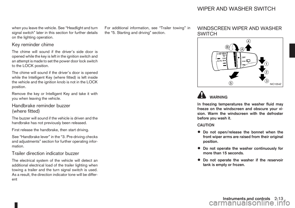
Push the lever down to operate the wiper at the fol-
lowing speeds:
j1Intermittent()
— the intermittent operation speed can be
adjusted by rotating the ring towards
jA
(slower) orjB (faster).
j2Low() – continuous low speed opera-
tion
j3High() – continuous high speed
operation
To stop the wiper operation, move the lever
up to the “OFF” position.
j4Single sweep() — push the lever up for
a single sweep operation of the wiper.
Washer operation
j
5 To operate the washer, pull the lever
towards you
j5 until the desired amount of
washer fluid is spread on the windscreen.
The wiper will automatically operate several
times.
The headlight cleaner (where fitted) will also
operate with operation of the windscreen
washer.
Headlight cleaner (where fitted)
The headlight washing system is only activated
when:
– the ignition switch is in the ON position.
– the headlight switch is in the
position.
– pulling the lever once towards you
j5.
NOTE
After the first operation, the headlight cleaner
operates once every fifth operation of the
windscreen washer.
CAUTION
Do not operate the headlight cleaner if the win-
dow washer fluid reservoir is empty.
Rain sensor (where fitted)
The rain sensor is activated when the intermittent
positionj1 (AUTO) of the wiper switch is selected.
The wiper will start to operate automatically at a suit-
able speed when rain is detected on the windscreen.
NOTE
The rain sensor is only intended for use during
rain or precipitation. During other weather condi-
tions no harm will come to the rain sensor sys-
tem if left active (wiper switch set to intermit-
tent), although occasional unexpected activation
of the wipers may occur.
REAR WINDOW
The rear window wiper and washer can be oper-
ated when the ignition switch is in the ON position.
Turn the switch clockwise to the intermittent (
,j1 ) position or continuous (,j2 ) position to
operate the wiper.
To operate the rear window washer, push the switch
towards the front of the vehicle
j3 . The rear win-
dow wiper will also operate.
CAUTION
•Do not operate the washer continuously for
more than 15 seconds.
•Do not operate the washer if the reservoir
tank is empty or frozen.
NIC1055Z
2-14Instruments and controls