2011 NISSAN MURANO seat adjustment
[x] Cancel search: seat adjustmentPage 55 of 433
Black plate (53,1)
Model "Z51-D" EDITED: 2010/ 7/ 23
through 8.
SSS0823
Forward-facing — step 10
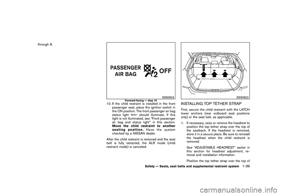
10. If the child restraint is installed in the frontpassenger seat, place the ignition switch in
the ON position. The front passenger air bag
status light
should illuminate. If this
light is not illuminated, see “Front passenger
air bag and status light” in this section.
Move the child restraint to another
seating position. Have the system
checked by a NISSAN dealer.
After the child restraint is removed and the seat
belt is fully retracted, the ALR mode (child
restraint mode) is canceled.
SSS0822
INSTALLING TOP TETHER STRAPFirst, secure the child restraint with the LATCH
lower anchors (rear outboard seat positions
only) or the seat belt, as applicable.
1. If necessary, raise or remove the headrest to position the top tether strap over the top of
the seatback. If the headrest is removed,
store it in a secure place. Be sure to reinstall
the headrest when the child restraint is
removed.
See “ADJUSTABLE HEADREST” earlier in
this section for headrest adjustment, re-
moval and installation information.
Position the top tether strap over the top of
Safety — Seats, seat belts and supplemental restraint system
1-39
Page 57 of 433
Black plate (55,1)
Model "Z51-D" EDITED: 2010/ 7/ 23
LRS0453
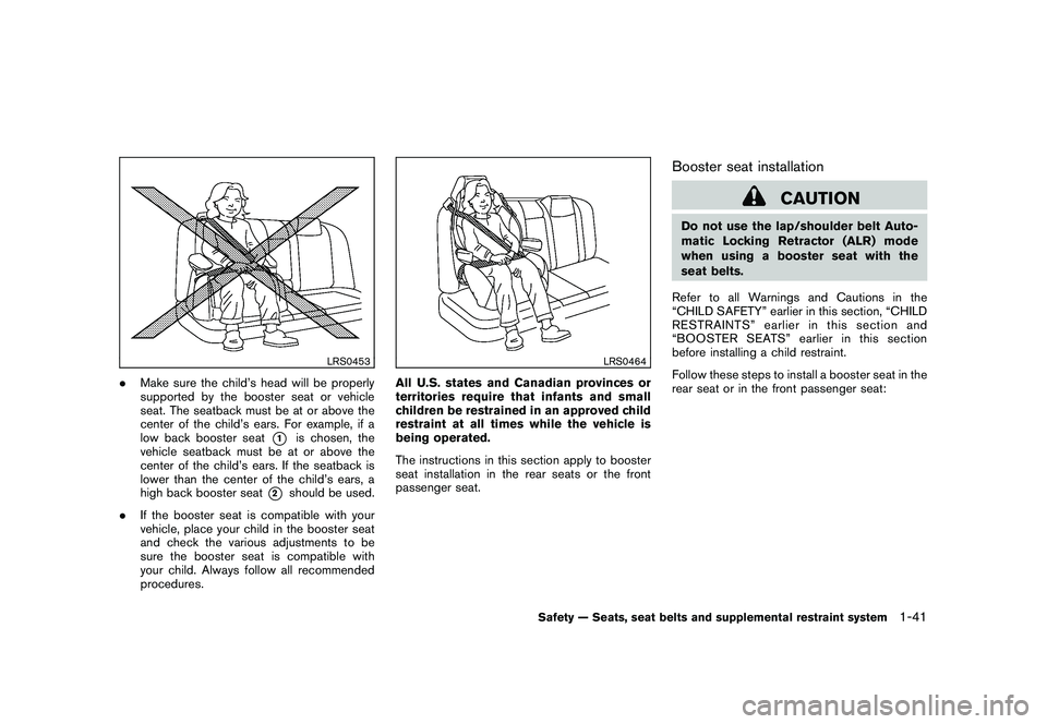
.Make sure the child’s head will be properly
supported by the booster seat or vehicle
seat. The seatback must be at or above the
center of the child’s ears. For example, if a
low back booster seat
*1
is chosen, the
vehicle seatback must be at or above the
center of the child’s ears. If the seatback is
lower than the center of the child’s ears, a
high back booster seat
*2
should be used.
. If the booster seat is compatible with your
vehicle, place your child in the booster seat
and check the various adjustments to be
sure the booster seat is compatible with
your child. Always follow all recommended
procedures.
LRS0464
All U.S. states and Canadian provinces or
territories require that infants and small
children be restrained in an approved child
restraint at all times while the vehicle is
being operated.
The instructions in this section apply to booster
seat installation in the rear seats or the front
passenger seat.
Booster seat installation
CAUTION
Do not use the lap/shoulder belt Auto-
matic Locking Retractor (ALR) mode
when using a booster seat with the
seat belts.
Refer to all Warnings and Cautions in the
“CHILD SAFETY” earlier in this section, “CHILD
RESTRAINTS” earlier in this section and
“BOOSTER SEATS” earlier in this section
before installing a child restraint.
Follow these steps to install a booster seat in the
rear seat or in the front passenger seat:
Safety — Seats, seat belts and supplemental restraint system
1-41
Page 58 of 433
Black plate (56,1)
Model "Z51-D" EDITED: 2010/ 7/ 23
SSS0640
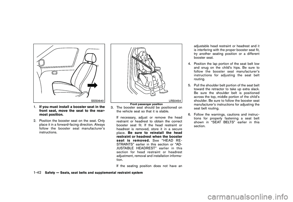
1.If you must install a booster seat in the
front seat, move the seat to the rear-
most position.
2. Position the booster seat on the seat. Only place it in a forward-facing direction. Always
follow the booster seat manufacturer’s
instructions.
LRS0454
Front passenger position
3. The booster seat should be positioned onthe vehicle seat so that it is stable.
If necessary, adjust or remove the head
restraint or headrest to obtain the correct
booster seat fit. If the head restraint or
headrest is removed, store it in a secure
place. Be sure to reinstall the head
restraint or headrest when the booster
seat is removed. See “HEAD RE-
STRAINTS” earlier in this section or “AD-
JUSTABLE HEADREST” earlier in this
section for head restraint or headrest
adjustment, removal and installation informa-
tion.
If the seating position does not have an adjustable head restraint or headrest and it
is interfering with the proper booster seat fit,
try another seating position or a different
booster seat.
4. Position the lap portion of the seat belt low and snug on the child’s hips. Be sure to
follow the booster seat manufacturer’s
instructions for adjusting the seat belt
routing.
5. Pull the shoulder belt portion of the seat belt toward the retractor to take up extra slack.
Be sure the shoulder belt is positioned
across the top, middle portion of the child’s
shoulder. Be sure to follow the booster seat
manufacturer’s instructions for adjusting the
seat belt routing.
6. Follow the warnings, cautions and instruc- tions for properly fastening a seat belt
shownin“SEATBELTS”earlierinthis
section.
1-42
Safety — Seats, seat belts and supplemental restraint system
Page 91 of 433
Black plate (89,1)
Model "Z51-D" EDITED: 2010/ 7/ 23
AUDIBLE REMINDERS
Key reminder chimeA chime will sound if the driver side door is
opened while the ignition switch is pushed to
the ACC position or pushed to the OFF or
LOCK position with the Intelligent Key left in the
Intelligent Key port. Make sure the ignition
switch is pushed to the OFF position, and take
the Intelligent Key with you when leaving the
vehicle.Light reminder chimeA chime will sound when the driver side door is
opened with the light switch in the
or
position and the ignition switch in the ACC
or OFF position.
Turn the light switch off when you leave the
vehicle.
Parking brake reminder chimeThe chime will sound if the vehicle is driven at
more than 4 MPH (7 km/h) with the parking
brake applied. Stop the vehicle and release the
parking brake.Seat belt warning chimeThe chime will sound for about 6 seconds
unless the driver’s seat belt is securely fastened.
Brake pad wear warningThe disc brake pads have audible wear warn-
ings. When a brake pad requires replacement, it
will make a high pitched scraping sound when
the vehicle is in motion. This scraping sound will
first occur only when the brake pedal is
depressed. After more wear of the brake pad,
the sound will always be heard even if the brake
pedal is not depresse d. Have the brakes
checked as soon as possible if the warning
sound is heard.
SIC3576
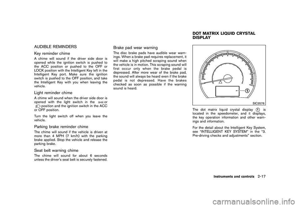
The dot matrix liquid crystal display
*1
is
located in the speedometer, and it displays,
the key operation information and other warn-
ings and information.
For the detail about the Intelligent Key System,
see “INTELLIGENT KEY SYSTEM” in the “3.
Pre-driving checks and adjustments” section.
DOT MATRIX LIQUID CRYSTAL
DISPLAY
Instruments and controls
2-17
Page 119 of 433
Black plate (117,1)
Model "Z51-D" EDITED: 2010/ 7/ 23
SIC3590
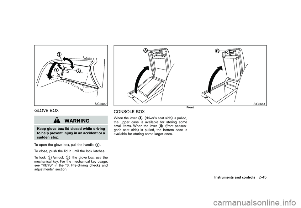
GLOVE BOX
WARNING
Keep glove box lid closed while driving
to help prevent injury in an accident or a
sudden stop.
To open the glove box, pull the handle
*1.
To close, push the lid in until the lock latches.
To lock
*2/unlock
*3
the glove box, use the
mechanical key. For the mechanical key usage,
see “KEYS” in the “3. Pre-driving checks and
adjustments” section.
SIC3654
Front
CONSOLE BOXWhen the lever
*A
(driver’s seat side) is pulled,
the upper case is available for storing some
small items. When the lever
*B
(front passen-
ger’s seat side) is pulled, the bottom case is
available for storing some larger ones.
Instruments and controls
2-45
Page 140 of 433
Black plate (138,1)
Model "Z51-D" EDITED: 2010/ 7/ 23
SPA2033
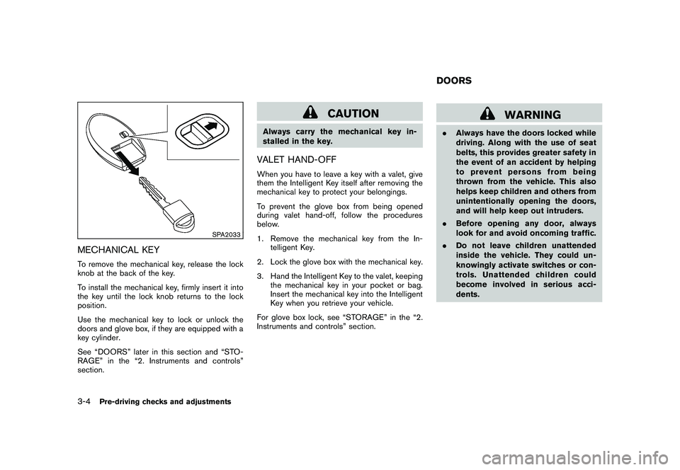
MECHANICAL KEYTo remove the mechanical key, release the lock
knob at the back of the key.
To install the mechanical key, firmly insert it into
the key until the lock knob returns to the lock
position.
Use the mechanical key to lock or unlock the
doors and glove box, if they are equipped with a
key cylinder.
See “DOORS” later in this section and “STO-
RAGE” in the “2. Instruments and controls”
section.
CAUTION
Always carry the mechanical key in-
stalled in the key.VALET HAND-OFFWhen you have to leave a key with a valet, give
them the Intelligent Key itself after removing the
mechanical key to protect your belongings.
To prevent the glove box from being opened
during valet hand-off, follow the procedures
below.
1. Remove the mechanical key from the In-telligent Key.
2. Lock the glove box with the mechanical key.
3. Hand the Intelligent Key to the valet, keeping the mechanical key in your pocket or bag.
Insert the mechanical key into the Intelligent
Key when you retrieve your vehicle.
For glove box lock, see “STORAGE” in the “2.
Instruments and controls” section.
WARNING
. Always have the doors locked while
driving. Along with the use of seat
belts, this provides greater safety in
the event of an accident by helping
to prevent persons from being
thrown from the vehicle. This also
helps keep children and others from
unintentionally opening the doors,
and will help keep out intruders.
. Before opening any door, always
look for and avoid oncoming traffic.
. Do not leave children unattended
inside the vehicle. They could un-
knowingly activate switches or con-
trols. Unattended children could
become involved in serious acci-
dents.DOORS
3-4
Pre-driving checks and adjustments
Page 162 of 433
Black plate (160,1)
Model "Z51-D" EDITED: 2010/ 7/ 23
SPA2833
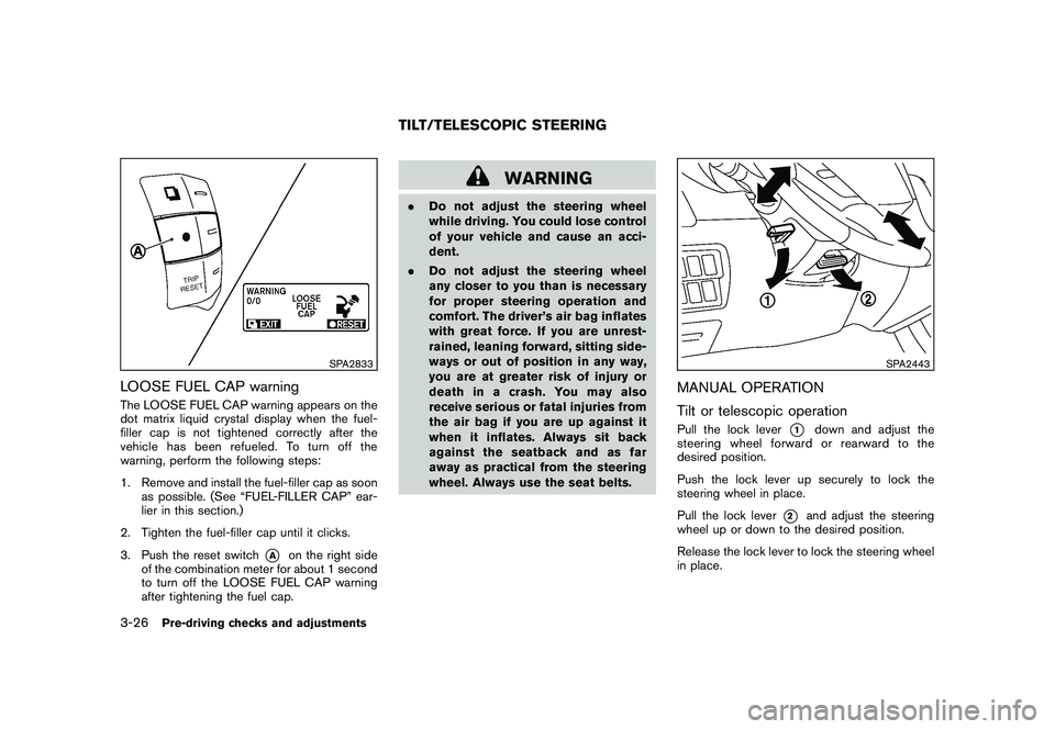
LOOSE FUEL CAP warningThe LOOSE FUEL CAP warning appears on the
dot matrix liquid crystal display when the fuel-
filler cap is not tightened correctly after the
vehicle has been refueled. To turn off the
warning, perform the following steps:
1. Remove and install the fuel-filler cap as soonas possible. (See “FUEL-FILLER CAP” ear-
lier in this section.)
2. Tighten the fuel-filler cap until it clicks.
3. Push the reset switch
*A
on the right side
of the combination meter for about 1 second
to turn off the LOOSE FUEL CAP warning
after tightening the fuel cap.
WARNING
. Do not adjust the steering wheel
while driving. You could lose control
of your vehicle and cause an acci-
dent.
. Do not adjust the steering wheel
any closer to you than is necessary
for proper steering operation and
comfort. The driver’s air bag inflates
with great force. If you are unrest-
rained, leaning forward, sitting side-
ways or out of position in any way,
you are at greater risk of injury or
death in a crash. You may also
receive serious or fatal injuries from
the air bag if you are up against it
when it inflates. Always sit back
against the seatback and as far
away as practical from the steering
wheel. Always use the seat belts.
SPA2443
MANUAL OPERATION
Tilt or telescopic operationPull the lock lever
*1
down and adjust the
steering wheel forward or rearward to the
desired position.
Push the lock lever up securely to lock the
steering wheel in place.
Pull the lock lever
*2
and adjust the steering
wheel up or down to the desired position.
Release the lock lever to lock the steering wheel
in place.
TILT/TELESCOPIC STEERING
3-26
Pre-driving checks and adjustments
Page 163 of 433
Black plate (161,1)
Model "Z51-D" EDITED: 2010/ 7/ 23
SPA2444A
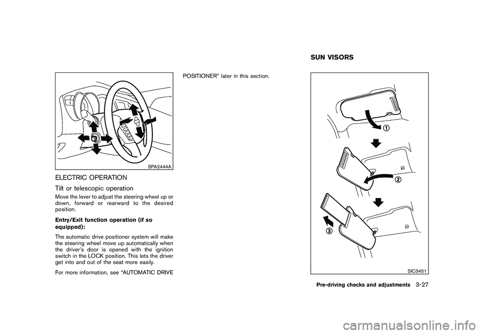
ELECTRIC OPERATION
Tilt or telescopic operationMove the lever to adjust the steering wheel up or
down, forward or rearward to the desired
position.
Entry/Exit function operation (if so
equipped):
The automatic drive positioner system will make
the steering wheel move up automatically when
the driver’s door is opened with the ignition
switch in the LOCK position. This lets the driver
get into and out of the seat more easily.
For more information, see “AUTOMATIC DRIVEPOSITIONER” later in this section.
SIC3451
SUN VISORSPre-driving checks and adjustments
3-27