2011 NISSAN MURANO steering wheel
[x] Cancel search: steering wheelPage 76 of 433

Black plate (74,1)
Model "Z51-D" EDITED: 2010/ 7/ 23
SSI0805
1. Heated steering wheel switch*
2. Side ventilator
3. Power lift gate switch*
4. Headlight, fog light* and turn signal switch
5. Fuel-filler door opener switch6. Steering-wheel-mounted controls (left side)*
— Audio control*
— Bluetooth
®Hands-Free Phone System control*
7. Meters and gauges 8. Steering wheel
— Horn
— Driver supplemental air bag
— Power steering system
9. Steering-wheel-mounted controls (right side) — Cruise control switches
10. Wiper and washer switch
11. Push-button ignition switch
12. Center ventilator
13. Center display — Center color display*
— Navigation system**
14. Heater/air conditioner control or Center multi-function control panel*
— Navigation system**
— Vehicle information and setting buttons*
15. Hazard warning flasher switch
16. Front passenger supplemental air bag
17. Vehicle Dynamic Control (VDC) OFF switch
18. Hood release handle
19. Power lift gate main switch*
20. Power seatback switch*
21. Fuse box cover
22. Parking brake
23. Tilting telescopic steering wheel lever or switch
24. Intelligent Key port
25. Audio system — Clock*
26. Heated seat switch*
27. Selector lever
28. Front passenger air bag status light
INSTRUMENT PANEL2-2
Instruments and controls
Page 87 of 433

Black plate (85,1)
Model "Z51-D" EDITED: 2010/ 7/ 23
Low tire pressure warning:
If the vehicle is being driven with low tire
pressure, the warning light will illuminate. A
CHECK TIRE PRESSURE warning also appears
on the dot matrix liquid crystal display.
When the low tire pressure warning light
illuminates, you should stop and adjust the tire
pressure to the recommended COLD tire
pressure shown on the Tire and Loading
Information label. The low tire pressure warning
light does not automatically turn off when the tire
pressure is adjusted. After the tire is inflated to
the recommended pressure, the vehicle must be
driven at speeds above 16 MPH (25 km/h) to
activate the TPMS and turn off the low tire
pressure warning light. Use a tire pressure
gauge to check the tire pressure.
The CHECK TIRE PRESSURE warning is active
as long as the low tire pressure warning light
remains illuminated.
For additional information, see “TIRE PRES-
SURE MONITORING SYSTEM (TPMS)” in the
“5. Starting and driving” section and “TIRE
PRESSURE MONITORING SYSTEM (TPMS)”
in the “6. In case of emergency” section.
TPMS malfunction:
If the TPMS is not functioning properly, the low
tire pressure warning light will flash for approxi-
mately 1 minute when the ignition switch ispushed ON. The light will remain on after the 1
minute. Have the system checked by a NISSAN
dealer. The CHECK TIRE PRESSURE warning
does not appear if the low tire pressure warning
light illuminates to indicate a TPMS malfunction.
For additional information, see “TIRE PRES-
SURE MONITORING SYSTEM (TPMS)” in the
“5. Starting and driving” section. For the
CHECK TIRE PRESSURE warning, see “DOT
MATRIX LIQUID CRYSTAL DISPLAY” later in
this section.
WARNING
.
If the light does not illuminate with
the ignition switch pushed ON, have
the vehicle checked by a NISSAN
dealer as soon as possible.
. If the light illuminates while driving,
avoid sudden steering maneuvers or
abrupt braking, reduce vehicle
speed, pull off the road to a safe
location and stop the vehicle as
soon as possible. Driving with un-
der-inflated tires may permanently
damage the tires and increase the
likelihood of tire failure. Serious
vehicle damage could occur and
may lead to an accident and could
result in serious personal injury. Check the tire pressure for all four
tires. Adjust the tire pressure to the
recommended COLD tire pressure
shownontheTireandLoading
Information label to turn the low
tire pressure warning light OFF. If
the light stays on after adjusting the
tire pressure and driving over 16
MPH (25 km/h) , have the system
checked by a NISSAN dealer. If you
have a flat tire, replace it with a
spare tire as soon as possible.
. When a spare tire is mounted or a
wheel is replaced, the TPMS will not
function and the low tire pressure
warning light will flash for approxi-
mately 1 minute. The light will
remain on after 1 minute. Contact
your NISSAN dealer as soon as
possible for tire replacement and/
or system resetting.
. Replacing tires with those not ori-
ginally specified by NISSAN could
affect the proper operation of the
TPMS.
Instruments and controls
2-13
Page 92 of 433

Black plate (90,1)
Model "Z51-D" EDITED: 2010/ 7/ 23
SIC4680
INDICATORS FOR OPERATION
1. Engine start operation indicatorThis indicator appears when the selector lever is
in the P (Park) position.
This indicator means that the engine will start bypushing the ignition switch with the brake pedal
depressed.
You can start the engine directly in any position.
2. Steering lock release malfunction
indicator (if so equipped)This indicator appears when the steering wheel
cannot be released from the LOCK position.
If this indicator appears, push the push-button
ignition switch while lightly turning the steering
2-18
Instruments and controls
Page 111 of 433

Black plate (109,1)
Model "Z51-D" EDITED: 2010/ 7/ 23
SIC2574
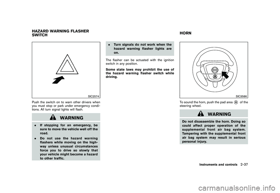
Push the switch on to warn other drivers when
you must stop or park under emergency condi-
tions. All turn signal lights will flash.
WARNING
.If stopping for an emergency, be
sure to move the vehicle well off the
road.
. Do not use the hazard warning
flashers while moving on the high-
way unless unusual circumstances
force you to drive so slowly that
your vehicle might become a hazard
to other traffic. .
Turn signals do not work when the
hazard warning flasher lights are
on.
The flasher can be actuated with the ignition
switch in any position.
Some state laws may prohibit the use of
the hazard warning flasher switch while
driving.
SIC3586
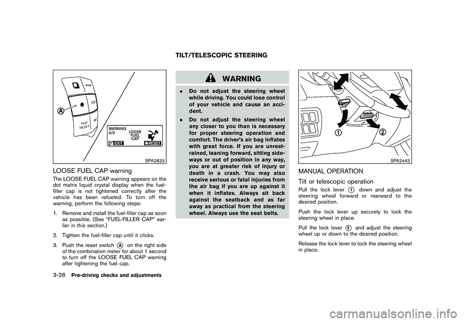
To sound the horn, push the pad area
*A
of the
steering wheel.
WARNING
Do not disassemble the horn. Doing so
could affect proper operation of the
supplemental front air bag system.
Tampering with the supplemental front
air bag system may result in serious
personal injury.
HAZARD WARNING FLASHER
SWITCH HORN
Instruments and controls
2-37
Page 112 of 433

Black plate (110,1)
Model "Z51-D" EDITED: 2010/ 7/ 23
SIC4401
The heated steering wheel system is designed
to operate only when the surface temperature of
the steering wheel is below 688F (20 8C) .
Push the heated steering wheel switch to warm
the steering wheel after the engine starts. The
indicator light
*1
on the switch will illuminate.
If the surface temperature of the steering wheel
is below 68 8F (20 8C) , the system will heat the
steering wheel and cycle off and on to maintain a
temperature above 68 8F (20 8C) . The indicator
light will remain on as long as the system is on.
Push the switch again to turn the heated
steering wheel system off manually. The indica-
tor light will turn off. NOTE:
If the surface temperature of the steering
wheel is above 68
8F (20 8C) when the switch
is turned on, the system will not heat the
steering wheel. This is not a malfunction.
WARNING
Do not use or allow occupants to use
the seat heater if you or the occupants
cannot monitor elevated seat tempera-
tures or have an inability to feel pain in
body parts that contact the seat. Use of
the seat heater by such people could
result in serious injury.
CAUTION
. The battery could run down if the
seat heater is operated while the
engine is not running.
. Do not use the seat heater for
extended periods or when no one
is using the seat.
. Do not put anything on the seat
which insulates heat, such as a
blanket, cushion, seat cover, etc.
Otherwise, the seat may become
overheated.
. Do not place anything hard or heavy
on the seat or pierce it with a pin or
similar object. This may result in
damage to the heater.
HEATED STEERING WHEEL (if so
equipped) HEATED SEATS (if so equipped)2-38
Instruments and controls
Page 162 of 433

Black plate (160,1)
Model "Z51-D" EDITED: 2010/ 7/ 23
SPA2833
LOOSE FUEL CAP warningThe LOOSE FUEL CAP warning appears on the
dot matrix liquid crystal display when the fuel-
filler cap is not tightened correctly after the
vehicle has been refueled. To turn off the
warning, perform the following steps:
1. Remove and install the fuel-filler cap as soonas possible. (See “FUEL-FILLER CAP” ear-
lier in this section.)
2. Tighten the fuel-filler cap until it clicks.
3. Push the reset switch
*A
on the right side
of the combination meter for about 1 second
to turn off the LOOSE FUEL CAP warning
after tightening the fuel cap.
WARNING
. Do not adjust the steering wheel
while driving. You could lose control
of your vehicle and cause an acci-
dent.
. Do not adjust the steering wheel
any closer to you than is necessary
for proper steering operation and
comfort. The driver’s air bag inflates
with great force. If you are unrest-
rained, leaning forward, sitting side-
ways or out of position in any way,
you are at greater risk of injury or
death in a crash. You may also
receive serious or fatal injuries from
the air bag if you are up against it
when it inflates. Always sit back
against the seatback and as far
away as practical from the steering
wheel. Always use the seat belts.
SPA2443
MANUAL OPERATION
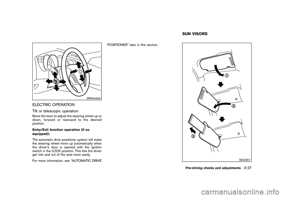
Tilt or telescopic operationPull the lock lever
*1
down and adjust the
steering wheel forward or rearward to the
desired position.
Push the lock lever up securely to lock the
steering wheel in place.
Pull the lock lever
*2
and adjust the steering
wheel up or down to the desired position.
Release the lock lever to lock the steering wheel
in place.
TILT/TELESCOPIC STEERING
3-26
Pre-driving checks and adjustments
Page 163 of 433

Black plate (161,1)
Model "Z51-D" EDITED: 2010/ 7/ 23
SPA2444A
ELECTRIC OPERATION
Tilt or telescopic operationMove the lever to adjust the steering wheel up or
down, forward or rearward to the desired
position.
Entry/Exit function operation (if so
equipped):
The automatic drive positioner system will make
the steering wheel move up automatically when
the driver’s door is opened with the ignition
switch in the LOCK position. This lets the driver
get into and out of the seat more easily.
For more information, see “AUTOMATIC DRIVEPOSITIONER” later in this section.
SIC3451
SUN VISORSPre-driving checks and adjustments
3-27
Page 167 of 433

Black plate (165,1)
Model "Z51-D" EDITED: 2010/ 7/ 23
SIC2064
VANITY MIRRORTo use the front vanity mirror, pull down the sun
visor and pull up the cover.The automatic drive positioner system has two
features:
.
Entry/exit function
. Memory storage
ENTRY/EXIT FUNCTIONThis system is designed so that the driver’s seat
and steering column will automatically move
when the selector lever is in the P (Park)
position. This allows the driver to get into and
out of the driver’s seat more easily.
The driver’s seat will slide backward and the
steering wheel will move up when the driver’s
door is opened with the ignition switch in the
LOCK position and the Intelligent Key not
inserted in the Intelligent Key port.
The driver’s seat and steering wheel will return
to the previous positions when the ignition
switch is pushed to the ACC position.
The driver’s seat will not return to the previous
positions if the seat or steering adjusting switch
is operated when the seat is at the exit position.Cancel or activate entry/exit functionThe selector lever must be in the P (Park)
position with the ignition switch in the OFF
position.
The entry/exit function can be activated or canceled by pressing and holding the SET
switch for more than 10 seconds.
The indicator lights on the memory switches (1
and 2) will blink once when the function is
canceled, and the indicator lights will blink twice
when the function is activated. Note that the
indicator lights may illuminate after 5 seconds
while holding the SET switch. This indicates
readiness for linking the Intelligent Key to a
stored memory position. Keep the SET switch
pressed for more than 10 seconds to turn on or
off the entry/exit function.
The entry/exit function can also be activated or
canceled if the “Lift Steering Wheel on Exit” key
or “Slide Driver Seat Back on Exit” key is turned
to ON or OFF in the “Comfort & Conv.” settings.
(See “VEHICLE INFORMATION AND SET-
TINGS” in the “4. Center display, heater, air
conditioner, audio, phone and voice recognition
systems” section.)
Initialize entry/exit functionIf the battery cable is disconnected, or if the fuse
opens, the entry/exit function will not work
though this function was set on before. In such
a case, after connecting the battery or replacing
with a new fuse, open and close the driver’s
door more than two times after the ignition
switch is placed in the LOCK position from the
ON position. The entry/exit function will be
activated.
AUTOMATIC DRIVE POSITIONER (if
so equipped)
Pre-driving checks and adjustments
3-31