Page 850 of 3787
PRECAUTIONSBR-3
< SERVICE INFORMATION >
C
DE
G H
I
J
K L
M A
B
BR
N
O P
5. When the repair work is completed, return the ignition switch to the ″LOCK ″ position before connecting
the battery cables. (At this time, the steering lock mechanism will engage.)
6. Perform a self-diagnosis check of al l control units using CONSULT-III.
Precaution for Brake SystemINFOID:0000000005928387
• Refill using recommended brake fluid. Refer to MA-14.
• Never reuse drained brake fluid.
• Be careful not to splash brake fluid on painted surface of body. If brake fluid is splashed on painted surfaces of body immediately wipe it off with cloth and then wash it away with water.
• To clean or wash all parts of master cylinder, disc brake caliper and wheel cylinder, use new brake fluid.
• Never use mineral oils such as gasoline or kerosene. They will ruin rubber parts of the hydraulic system.
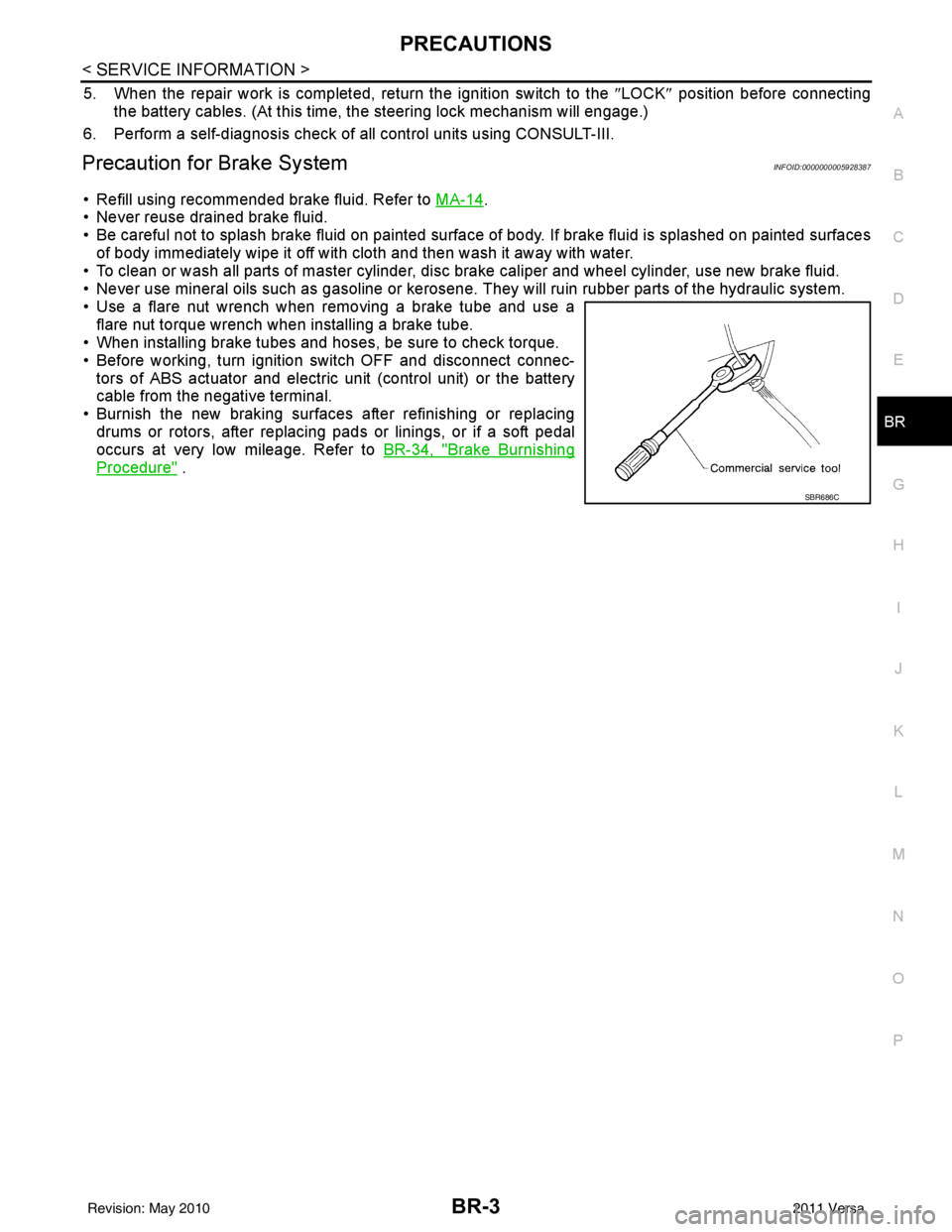
• Use a flare nut wrench when removing a brake tube and use a flare nut torque wrench when installing a brake tube.
• When installing brake tubes and hoses, be sure to check torque.
• Before working, turn igniti on switch OFF and disconnect connec-
tors of ABS actuator and electric unit (control unit) or the battery
cable from the negative terminal.
• Burnish the new braking surfaces after refinishing or replacing drums or rotors, after replacing p ads or linings, or if a soft pedal
occurs at very low mileage. Refer to BR-34, "
Brake Burnishing
Procedure" .
SBR686C
Revision: May 2010 2011 Versa
Page 852 of 3787
NOISE, VIBRATION AND HARSHNESS (NVH) TROUBLESHOOTINGBR-5
< SERVICE INFORMATION >
C
DE
G H
I
J
K L
M A
B
BR
N
O P
NOISE, VIBRATION AND HARSHN ESS (NVH) TROUBLESHOOTING
NVH Troubleshooting ChartINFOID:0000000005928390
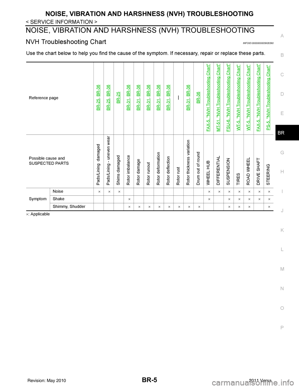
Use the chart below to help you find t he cause of the symptom. If necessary, repair or replace these parts.
×: ApplicableReference page
BR-25
,
BR-36
BR-25
, BR-36BR-25
BR-31
, BR-36
BR-31
, BR-36
BR-31
, BR-36
BR-31
, BR-36
BR-31
, BR-36—
BR-31, BR-36BR-36
FAX-5, "
NVH Troubleshooting Chart
"
MT-51, "
NVH Troubleshooting Chart
"
FSU-6, "
NVH Troubleshooting Chart
"
WT-5, "
NVH Troubleshooting Chart
"
WT-5, "
NVH Troubleshooting Chart
"
FAX-5, "
NVH Troubleshooting Chart
"
PS-5, "
NVH Troubleshooting Chart
"
Possible cause and
SUSPECTED PARTS
Pads/Lining damaged
Pads/Lining - uneven wear
Shims damaged
Rotor imbalance
Rotor damage
Rotor runout
Rotor deformation
Rotor deflection
Rotor rust
Rotor thickness variation
Drum out of round
WHEEL HUB
DIFFERENTIAL
SUSPENSION
TIRES
ROAD WHEEL
DRIVE SHAFT
STEERING
Symptom Noise
××× ×××××××
Shake × × ×××××
Shimmy, Shudder ×××××××× ××× ×
Revision: May 2010 2011 Versa
Page 856 of 3787
BRAKE FLUIDBR-9
< SERVICE INFORMATION >
C
DE
G H
I
J
K L
M A
B
BR
N
O P
BRAKE FLUID
On Board InspectionINFOID:0000000005928393
CHECKING BRAKE FLUID LEVEL
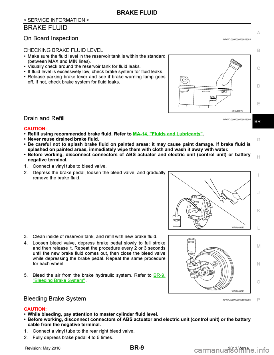
• Make sure the fluid level in the reservoir tank is within the standard (between MAX and MIN lines).
• Visually check around the reservoir tank for fluid leaks.
• If fluid level is excessively low, check brake system for fluid leaks.
• Release parking brake lever and see if brake warning lamp goes off. If not, check brake system for fluid leaks.
Drain and RefillINFOID:0000000005928394
CAUTION:
• Refill using recommended brake fluid. Refer to MA-14, "
Fluids and Lubricants".
• Never reuse drained brake fluid.
• Be careful not to splash brake fluid on painted areas; it may cause paint damage. If brake fluid is
splashed on painted areas, immediately wipe th em with cloth and wash it away with water.
• Before working, disconnect connect ors of ABS actuator and electric unit (control unit) or battery
negative terminal.
1. Connect a vinyl tube to bleed valve.
2. Depress the brake pedal, loosen the bleed valve, and gradually remove the brake fluid.
3. Clean inside of reservoir tank, and refill with new brake fluid.
4. Loosen bleed valve, depress brake pedal slowly to full stroke and then release it. Repeat the procedure every 2 or 3 seconds
until the new brake fluid comes out, then close the bleed valve
while depressing the brake pedal . Repeat the same procedure
for each wheel.
5. Bleed the air from the brake hydraulic system. Refer to BR-9,
"Bleeding Brake System" .
Bleeding Brake SystemINFOID:0000000005928395
CAUTION:
• While bleeding, pay attention to master cylinder fluid level.
• Before working, disconnect connectors of ABS actuator and electri c unit (control unit) or the battery
cable from the negative terminal.
1. Connect a vinyl tube to the rear right bleed valve.
2. Fully depress brake pedal 4 to 5 times.
SFIA3067E
WFIA0512E
WFIA0513E
Revision: May 2010 2011 Versa
Page 873 of 3787
BR-26
< SERVICE INFORMATION >
FRONT DISC BRAKE
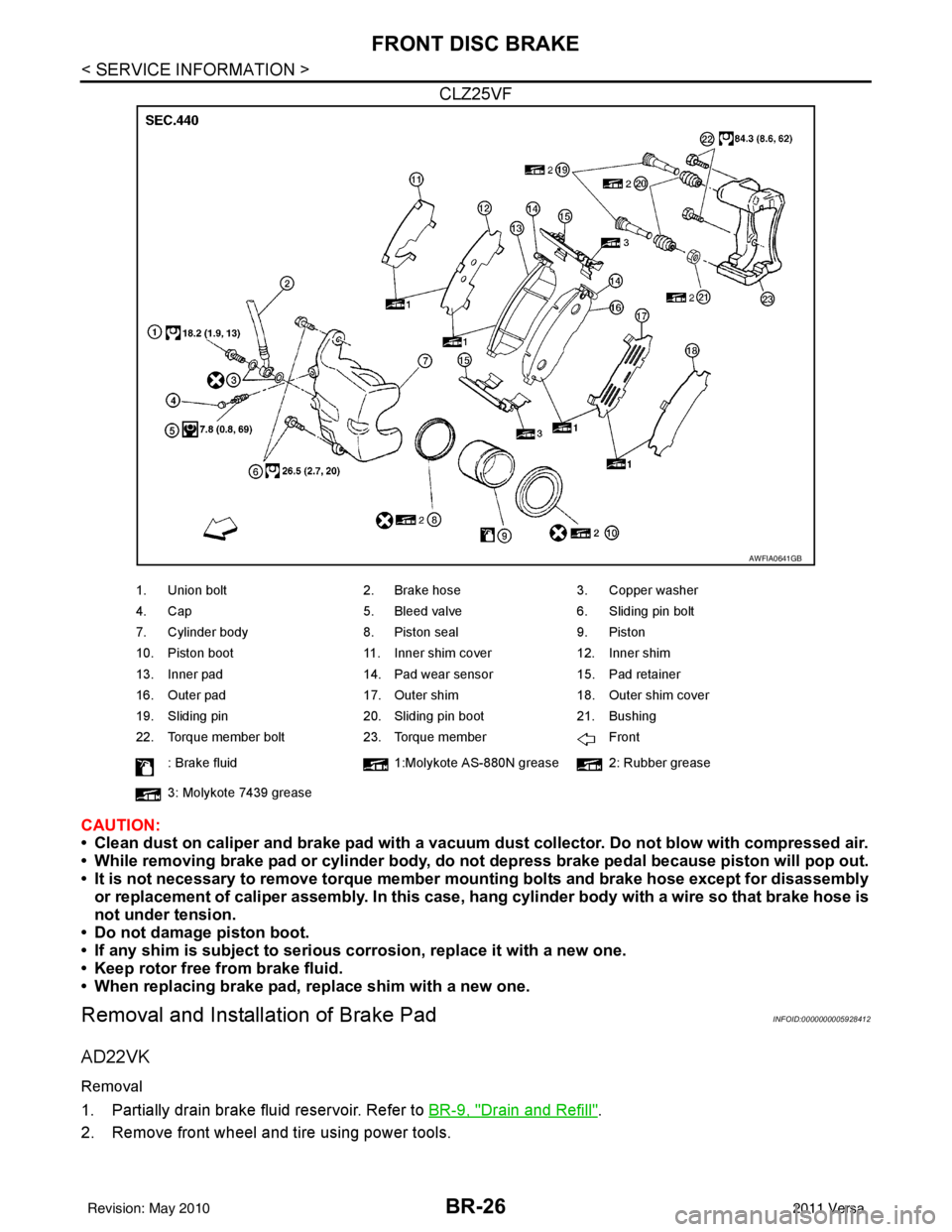
CLZ25VF
CAUTION:
• Clean dust on caliper and brake pad with a vacuum dust collector. Do not blow with compressed air.
• While removing brake pad or cylinder body, do not depress brake pedal because piston will pop out.
• It is not necessary to remove torque member mounting bolts and brake hose except for disassembly
or replacement of caliper assembly. In this case, hang cylinder body with a wire so that brake hose is
not under tension.
• Do not damage piston boot.
• If any shim is subject to serious corrosion, replace it with a new one.
• Keep rotor free from brake fluid.
• When replacing brake pad, replace shim with a new one.
Removal and Installation of Brake PadINFOID:0000000005928412
AD22VK
Removal
1. Partially drain brake fluid reservoir. Refer to BR-9, "Drain and Refill".
2. Remove front wheel and tire using power tools.
AWFIA0641GB
1. Union bolt 2. Brake hose3. Copper washer
4. Cap 5. Bleed valve6. Sliding pin bolt
7. Cylinder body 8. Piston seal9. Piston
10. Piston boot 11. Inner shim cover12. Inner shim
13. Inner pad 14. Pad wear sensor15. Pad retainer
16. Outer pad 17. Outer shim18. Outer shim cover
19. Sliding pin 20. Sliding pin boot21. Bushing
22. Torque member bolt 23. Torque member Front
: Brake fluid 1:Molykote AS-880N grease 2: Rubber grease
3: Molykote 7439 grease
Revision: May 2010 2011 Versa
Page 875 of 3787
BR-28
< SERVICE INFORMATION >
FRONT DISC BRAKE
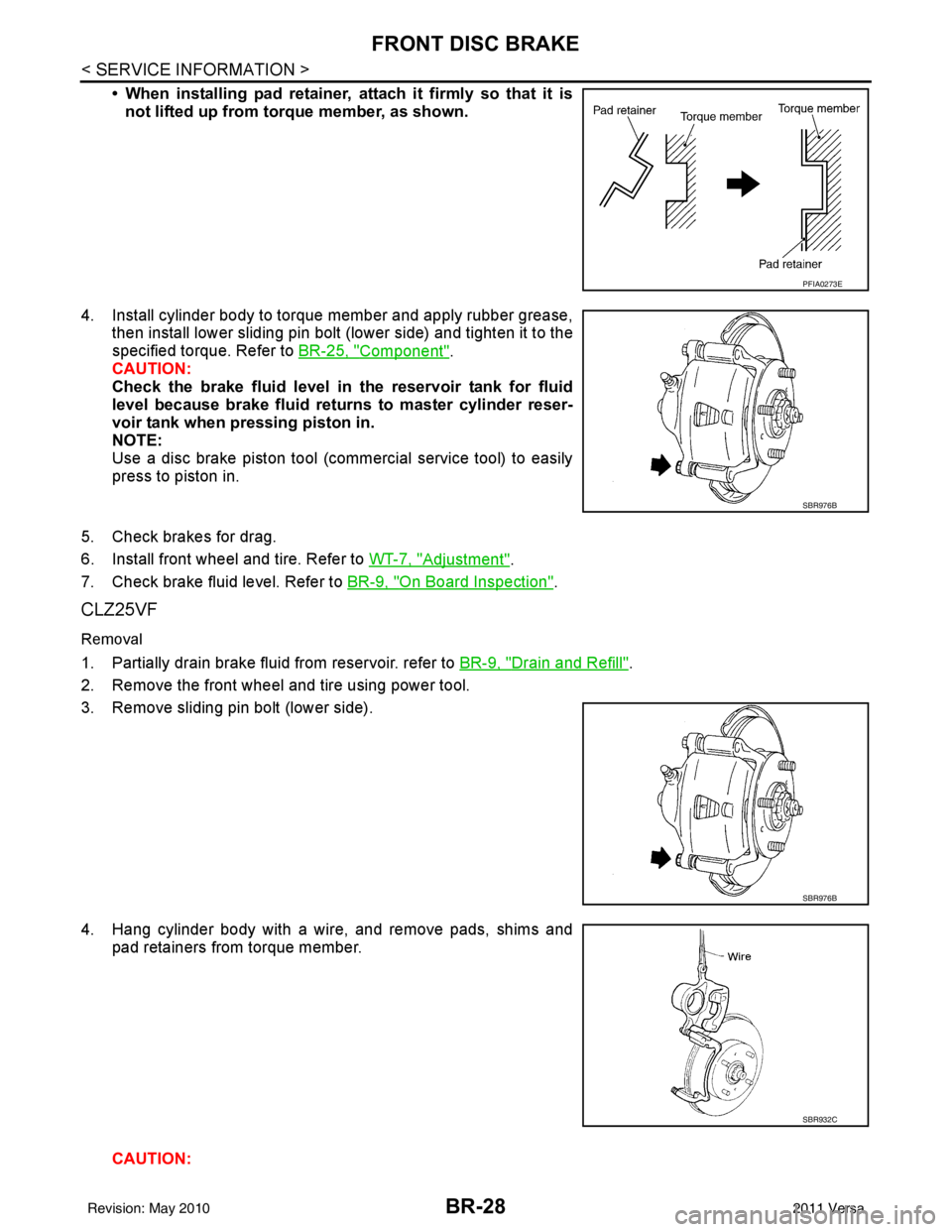
• When installing pad retainer, attach it firmly so that it isnot lifted up from torque member, as shown.
4. Install cylinder body to torque member and apply rubber grease, then install lower sliding pin bolt (lower side) and tighten it to the
specified torque. Refer to BR-25, "
Component".
CAUTION:
Check the brake fluid level in the reservoir tank for fluid
level because brake fluid returns to master cylinder reser-
voir tank when pressing piston in.
NOTE:
Use a disc brake piston tool (commercial service tool) to easily
press to piston in.
5. Check brakes for drag.
6. Install front wheel and tire. Refer to WT-7, "
Adjustment".
7. Check brake fluid level. Refer to BR-9, "
On Board Inspection".
CLZ25VF
Removal
1. Partially drain brake fluid from reservoir. refer to BR-9, "Drain and Refill".
2. Remove the front wheel and tire using power tool.
3. Remove sliding pin bolt (lower side).
4. Hang cylinder body with a wire, and remove pads, shims and pad retainers from torque member.
CAUTION:
PFIA0273E
SBR976B
SBR976B
SBR932C
Revision: May 2010 2011 Versa
Page 876 of 3787
FRONT DISC BRAKEBR-29
< SERVICE INFORMATION >
C
DE
G H
I
J
K L
M A
B
BR
N
O P
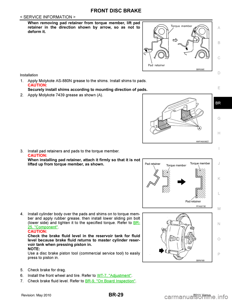
When removing pad retainer from torque member, lift pad
retainer in the direction shown by arrow, so as not to
deform it.
Installation
1. Apply Molykote AS-880N grease to the shims. Install shims to pads. CAUTION:
Securely install shims according to mounting direction of pads.
2. Apply Molykote 7439 grease as shown (A).
3. Install pad retainers and pads to the torque member. CAUTION:
When installing pad retainer, att ach it firmly so that it is not
lifted up from torque member, as shown.
4. Install cylinder body over the pads and shims on to torque mem- ber and apply rubber grease, then install lower sliding pin bolt
(lower side) and tighten it to the specified torque. Refer to BR-
25, "Component".
CAUTION:
Check the brake fluid level in th e reservoir tank for fluid
level because brake fluid returns to master cylinder reser-
voir tank when pressing piston in.
NOTE:
Use a disc brake piston tool (commercial service tool) to easily
press to piston in.
5. Check brake for drag.
6. Install the front wheel and tire. Refer to WT-7, "
Adjustment".
7. Check brake fluid level. Refer to BR-9, "
On Board Inspection".
SBR556E
AWFIA0039ZZ
PFIA0273E
SBR976B
Revision: May 2010 2011 Versa
Page 877 of 3787
BR-30
< SERVICE INFORMATION >
FRONT DISC BRAKE
Removal and Installation of Brake Caliper Assembly
INFOID:0000000005928413
REMOVAL
1. Remove front wheel and tire.
2. Secure the disc rotor using wheel nuts.
CAUTION:
Put matching marks on wheel hub assembly and disc rotor,
if it is necessary to remove the disc rotor.
3. Drain brake fluid. Refer to BR-9, "
Drain and Refill".
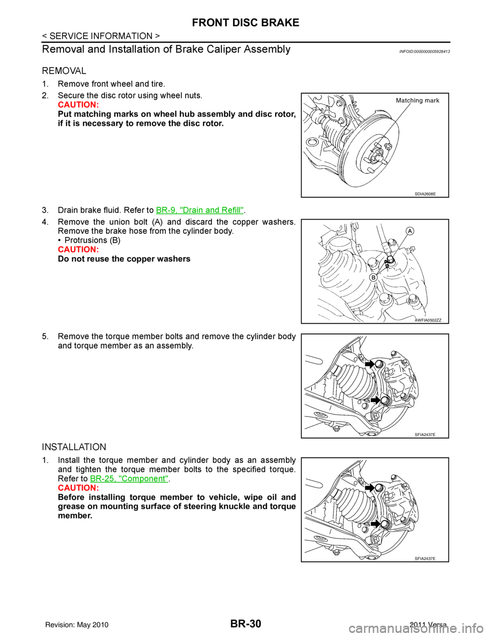
4. Remove the union bolt (A) and discard the copper washers. Remove the brake hose from the cylinder body.
• Protrusions (B)
CAUTION:
Do not reuse the copper washers
5. Remove the torque member bolts and remove the cylinder body and torque member as an assembly.
INSTALLATION
1. Install the torque member and cylinder body as an assemblyand tighten the torque member bolts to the specified torque.
Refer to BR-25, "
Component".
CAUTION:
Before installing torque member to vehicle, wipe oil and
grease on mounting surface of steering knuckle and torque
member.
SDIA2608E
AWFIA0502ZZ
SFIA2437E
SFIA2437E
Revision: May 2010 2011 Versa
Page 878 of 3787
FRONT DISC BRAKEBR-31
< SERVICE INFORMATION >
C
DE
G H
I
J
K L
M A
B
BR
N
O P
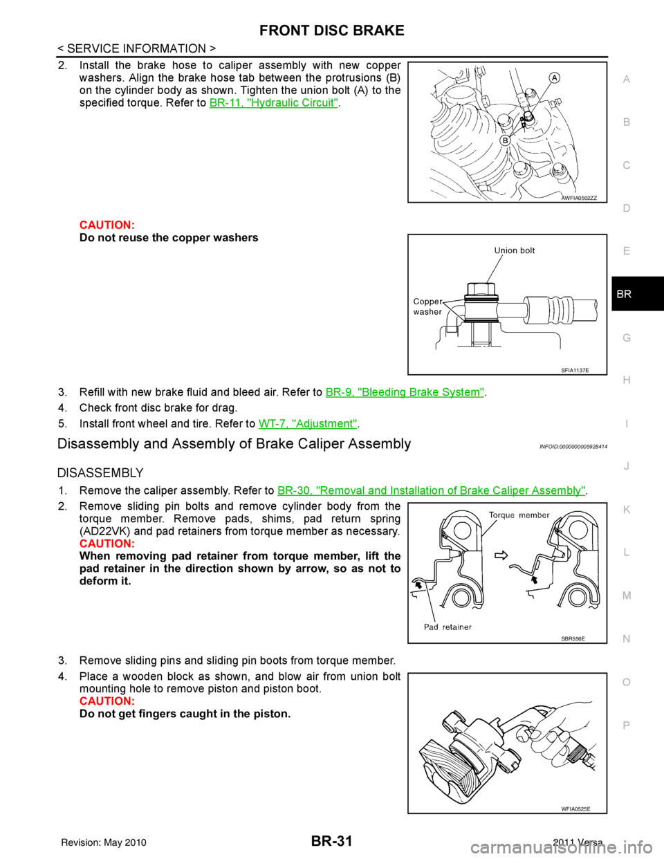
2. Install the brake hose to caliper assembly with new copper washers. Align the brake hose tab between the protrusions (B)
on the cylinder body as shown. Tighten the union bolt (A) to the
specified torque. Refer to BR-11, "
Hydraulic Circuit".
CAUTION:
Do not reuse the copper washers
3. Refill with new brake fluid and bleed air. Refer to BR-9, "
Bleeding Brake System".
4. Check front disc brake for drag.
5. Install front wheel and tire. Refer to WT-7, "
Adjustment".
Disassembly and Assembly of Brake Caliper AssemblyINFOID:0000000005928414
DISASSEMBLY
1. Remove the caliper assembly. Refer to BR-30, "Removal and Installation of Brake Caliper Assembly".
2. Remove sliding pin bolts and remove cylinder body from the torque member. Remove pads, shims, pad return spring
(AD22VK) and pad retainers from torque member as necessary.
CAUTION:
When removing pad retainer from torque member, lift the
pad retainer in the direction shown by arrow, so as not to
deform it.
3. Remove sliding pins and sliding pin boots from torque member.
4. Place a wooden block as shown, and blow air from union bolt mounting hole to remove piston and piston boot.
CAUTION:
Do not get fingers caught in the piston.
AWFIA0502ZZ
SFIA1137E
SBR556E
WFIA0525E
Revision: May 2010 2011 Versa