Page 66 of 3787
TROUBLE DIAGNOSISAT-49
< SERVICE INFORMATION >
DE
F
G H
I
J
K L
M A
B
AT
N
O P
A/T Electrical Parts LocationINFOID:0000000005928092
1. OD OFF indicator lamp 2. Shift position indicator3. Accelerator pedal position (APP)
sensor
4. Input speed sensor 5. Transmission range switch6. Terminal body (Terminal cord as-
sembly connector)
BCIA0037E
Revision: May 2010 2011 Versa
Page 67 of 3787
AT-50
< SERVICE INFORMATION >
TROUBLE DIAGNOSIS
Circuit Diagram
INFOID:0000000005928093
7. Output speed sensor 8. Dropping resistor 9. TCM
10. Overdrive control switch
ABDWA0413GB
Revision: May 2010 2011 Versa
Page 68 of 3787
TROUBLE DIAGNOSISAT-51
< SERVICE INFORMATION >
DE
F
G H
I
J
K L
M A
B
AT
N
O P
Inspections Before Trouble DiagnosisINFOID:0000000005928094
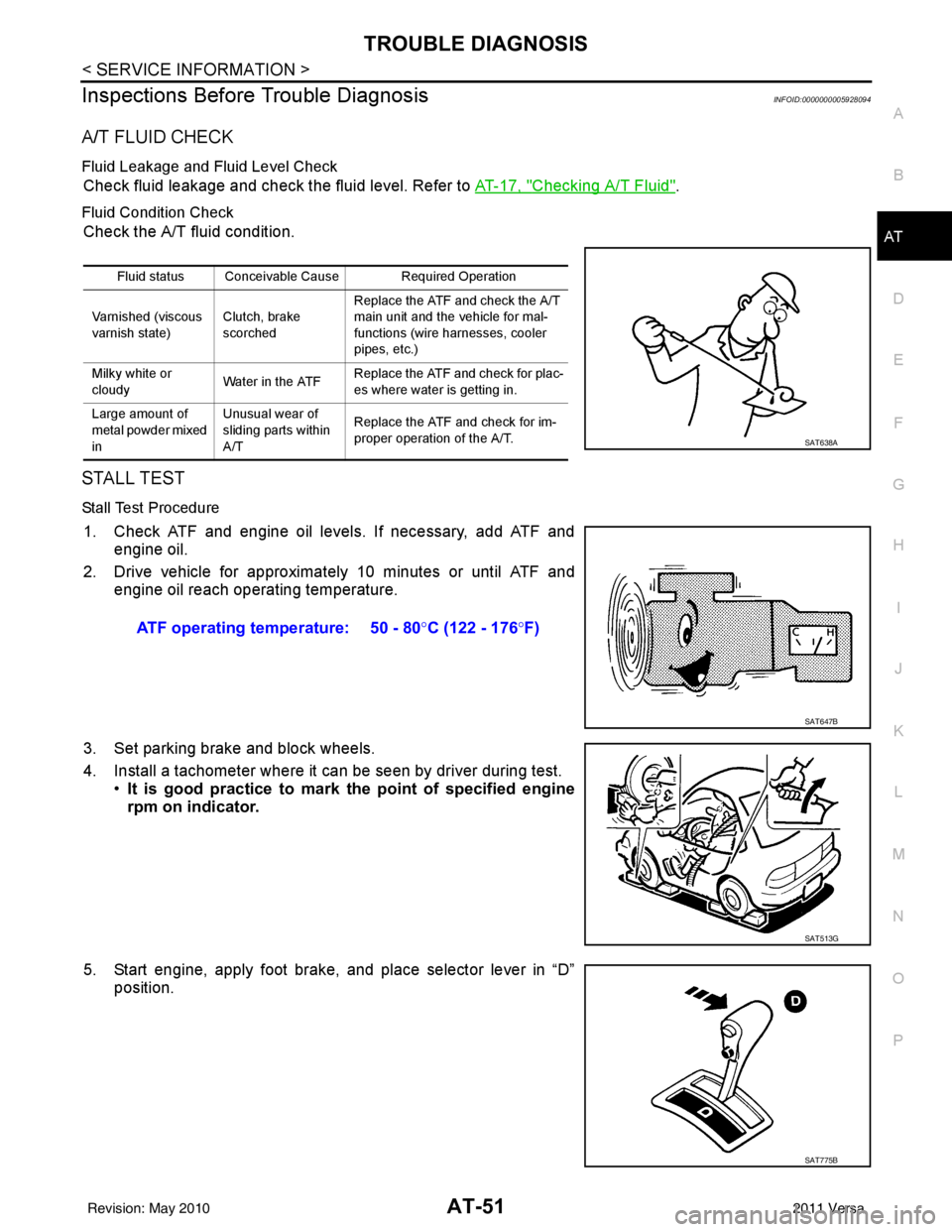
A/T FLUID CHECK
Fluid Leakage and Fluid Level Check
Check fluid leakage and check the fluid level. Refer to AT-17, "Checking A/T Fluid".
Fluid Condition Check
Check the A/T fluid condition.
STALL TEST
Stall Test Procedure
1. Check ATF and engine oil levels. If necessary, add ATF and engine oil.
2. Drive vehicle for approximately 10 minutes or until ATF and engine oil reach operating temperature.
3. Set parking brake and block wheels.
4. Install a tachometer where it can be seen by driver during test. •It is good practice to mark the point of specified engine
rpm on indicator.
5. Start engine, apply foot brake, and place selector lever in “D” position.
Fluid status Conceivable Cause Required Operation
Varnished (viscous
varnish state) Clutch, brake
scorchedReplace the ATF and check the A/T
main unit and the vehicle for mal-
functions (wire harnesses, cooler
pipes, etc.)
Milky white or
cloudy Water in the ATFReplace the ATF and check for plac-
es where water is getting in.
Large amount of
metal powder mixed
in Unusual wear of
sliding parts within
A/T
Replace the ATF and check for im-
proper operation of the A/T.
SAT638A
ATF operating temperature: 50 - 80
°C (122 - 176 °F)
SAT647B
SAT513G
SAT775B
Revision: May 2010 2011 Versa
Page 69 of 3787

AT-52
< SERVICE INFORMATION >
TROUBLE DIAGNOSIS
6. Accelerate to wide open throttle gradually while applying footbrake.
7. Quickly note the engine stall revolution and immediately release throttle.
CAUTION:
Do not hold down the accelerator pedal for more than 5 sec-
onds during this test.
8. Move selector lever to “N” position.
9. Cool off ATF. CAUTION:
Run the engine at idle for at least 1 minute.
10. Repeat steps 6 through 9 with selector lever in “2”, “1” and “R” positions.
Judgement of Stall Test
The test result and possible damaged components relating to each result are shown in the illustrations on next
page.
In order to pinpoint the possible damaged components, refer to AT-43, "
How to Perform Trouble Diagnosis for
Quick and Accurate Repair".
NOTE:
Stall revolution is too high in “D”, “2”, or “1” position:
• Slippage occurs in 1GR but not in 2GR and 3GR. ..... Low one-way clutch slippage
• Slippage occurs in the following gears:
1GR through 3GR in “D” position and engine brake functions with OD OFF. (OD OFF indicator lamp is on.)
1GR and 2GR in “2” position and engine brake functions with accelerator pedal released (fully closed throt-
tle)...... Forward clutch or forward one-way clutch slippage
Stall revolution is too high in “R” position:
• Engine brake does not function in “1” posit ion. ..... Low & reverse brake slippage
• Engine brake functions in “1” position. ..... Reverse clutch slippage
Stall revolution within specifications:
• Vehicle does not achieve speed of more than 80 km/h ( 50 MPH). ..... One-way clutch seizure in torque con-
verter housing
CAUTION:
Be careful because automatic flui d temperature increases abnormally:
• Slippage occurs in 3GR and 4GR in “D” position. ..... High clutch slippage
• Slippage occurs in 2GR and 4GR in “D” position. ..... Brake band slippage
• Engine brake does not function in 2GR and 3GR in “D” pos ition, 2GR in “2” position, and 1GR in “1” position
with OD OFF. (OD OFF indicator lamp is on.) ..... Overrun clutch slippage
Stall revolution less than specifications:
• Poor acceleration during starts. ..... One-way clutch seizure in torque converter Stall revolution:
AT-374, "
Stall Speed"
SAT514G
SAT771B
Revision: May 2010 2011 Versa
Page 70 of 3787
TROUBLE DIAGNOSISAT-53
< SERVICE INFORMATION >
DE
F
G H
I
J
K L
M A
B
AT
N
O P
LINE PRESSURE TEST
Line Pressure Test Ports
SCIA7987E
Revision: May 2010 2011 Versa
Page 71 of 3787
AT-54
< SERVICE INFORMATION >
TROUBLE DIAGNOSIS
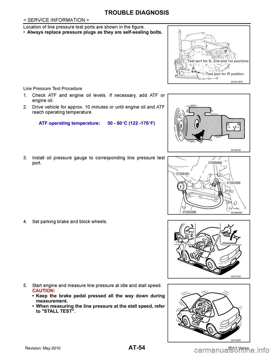
Location of line pressure test ports are shown in the figure.
•Always replace pressure plugs as they are self-sealing bolts.
Line Pressure Test Procedure
1. Check ATF and engine oil levels. If necessary, add ATF or
engine oil.
2. Drive vehicle for approx. 10 minutes or until engine oil and ATF reach operating temperature.
3. Install oil pressure gauge to corresponding line pressure test port.
4. Set parking brake and block wheels.
5. Start engine and measure line pressure at idle and stall speed. CAUTION:
• Keep the brake pedal pressed all the way down duringmeasurement.
• When measuring the line pressure at the stall speed, refer to "STALL TEST".
SCIA7187E
ATF operating temperature: 50 - 80° C (122 -176°F)
SAT647B
SCIA6528J
SAT513G
SAT493G
Revision: May 2010 2011 Versa
Page 72 of 3787

TROUBLE DIAGNOSISAT-55
< SERVICE INFORMATION >
DE
F
G H
I
J
K L
M A
B
AT
N
O P
Line Pressure
Judgement of Line Pressure Test
Road TestINFOID:0000000005928095
DESCRIPTION
• The purpose of the test is to det
ermine overall performance of A/T
and analyze causes of malfunctions.
• The road test consists of the following three parts:
1. Check before engine is started. Refer to AT- 5 6
.
2. Check at idle. Refer to AT- 5 6
.
3. Cruise test • Inspection all the item from Part 1 to Part 3. Refer to AT- 5 8
,
AT- 6 1
and AT- 6 2 .
Engine speed Line pressure [kPa (kg/cm
2 , psi)]
D, 2nd and 1st positions R position
Idle speed AT- 3 7 4 , "
Line Pressure"Sta ll sp ee d
JudgementSuspected parts
At idle Line pressure is low in all positions. • Oil pump wear
• Control piston damage
• Pressure regulator valve or plug sticking
• Spring for pressure regulator valve damaged
• Fluid pressure leakage between oil strainer and pressure regulator valve
• Clogged strainer
Line pressure is low in particular posi-
tion. • Fluid pressure leakage between manual valve and particular clutch
• For example, line pressure is:
− Low in “R” and “1 ” positions, but
− Normal in “D”, and “2” positions.
Therefore, fluid leakage exists at or around low and reverse brake circuit.
Refer to AT- 2 2 , "
Shift Mechanism".
Line pressure is high. • Accelerator pedal position signal malfunction
• A/T fluid temperature sensor damaged
• Line pressure solenoid valve sticking
• Short circuit of line pressure solenoid valve circuit
• Pressure modifier valve sticking
• Pressure regulator valve or plug sticking
• Open in dropping resistor circuit
At stall
speed Line pressure is low.
• Accelerator pedal position signal malfunction
• Line pressure solenoid valve sticking
• Short circuit of line pressure solenoid valve circuit
• Pressure regulator valve or plug sticking
• Pressure modifier valve sticking
• Pilot valve sticking
SAT786A
Revision: May 2010 2011 Versa
Page 73 of 3787

AT-56
< SERVICE INFORMATION >
TROUBLE DIAGNOSIS
• Before road test, familiarize yourself with all test procedures anditems to check.
• Test all inspection items until the symptom is uncovered. Include
NG items in “Diagnostic Wo rksheet Chart”(Refer to AT- 4 3
). Per-
form a diagnosis of the NG items after the completion of all the
road tests.
Check Before Engine Is StartedINFOID:0000000005928096
1.CHECK OD OFF INDICATOR LAMP
1. Park vehicle on flat surface.
2. Move selector lever to “P” position.
3. Turn ignition switch OFF. Wait at least 5 seconds.
4. Turn ignition switch ON. (Do not start engine.)
Does OD OFF indicator lamp come on for about 2 seconds?
YES >> 1. Turn ignition switch OFF. 2. Perform self-diagnosis and note NG items.Refer to AT-77, "
CONSULT-III Function (TRANS-
MISSION)" , AT-82, "Diagnosis Procedure without
CONSULT-III" .
3. Go to AT-56, "
Check at Idle" .
NO >> Stop “Road Test”. Go to AT-180, "
OD OFF Indicator
Lamp Does Not Come On" .
Check at IdleINFOID:0000000005928097
1.CHECK ENGINE START
1. Park vehicle on flat surface.
2. Turn ignition switch ON. (Do not start engine.)
3. Move selector lever to “P” or “N” position.
4. Turn ignition switch to “START” position.
Is engine started?
YES >> GO TO 2.
NO >> • Stop “Road Test”. Mark the box on the “Diagnostic Worksheet Chart”.
•Go to AT-182, "
Engine Cannot Be Started in "P" and
"N" Position" .
2.CHECK ENGINE START
1. Turn ignition switch ON. (Do not start engine.)
SAT496G
SAT772B
SCIA7140E
SAT769B
Revision: May 2010 2011 Versa