Page 3739 of 3787
TROUBLE DIAGNOSIS FOR SELF-DIAGNOSTIC ITEMS
WT-21
< SERVICE INFORMATION >
C
D F
G H
I
J
K L
M A
B
WT
N
O P
Can ID registration of all transmitters be completed?
YES >> GO TO 3.
NO >> GO TO WT-20, "
Data from Transmitter Not Being Received".
3.DRIVE VEHICLE
1. Drive at a speed of 40 km/h (25 MPH) or more fo r 3 minutes, and then drive the vehicle at any speed for
10 minutes.
2. Check all tire pressures with CONSULT-III within 5 minutes.
Does
“DATA MONITOR ITEM” display tire pressure as normal without any warning lamp?
YES >> Inspection End.
NO >> Replace malfunctioning transmitter, and perform Step 3 again. Refer to WT-26, "
Transmitter
(Pressure Sensor)".
Transmitter Pressure MalfunctionINFOID:0000000005931114
MALFUNCTION CODE NO. 35, 36, 37 OR 38 (DTC C1716, C1717, C1718 OR C1719)
1.CHECK ALL TIRE PRESSURES
Check all tire pressures. Refer to WT-28, "
Tire".
Are there any tires with pressure of 64 psi or more?
YES >> Adjust tire pressure to specified value.
NO >> GO TO 2.
2.ID REGISTRATION AND VEHICLE DRIVING
1. Carry out ID registration of all transmitters. Refer to WT-13, "
ID Registration Procedure".
2. Drive at a speed of 40 km/h (25 MPH) or more for several minutes without stopping.
3. Check all tire pressures with CONSULT-III within 15 minutes after vehicle speed becomes 17 km/h (11 MPH).
Does
“DATA MONITOR ITEM” display 64 psi or more?
YES >> Replace transmitter. Refer to WT-26, "Transmitter (Pressure Sensor)". GO TO 3.
NO >> GO TO 3.
3.ID REGISTRATION AND VEHICLE DRIVING
1. Carry out ID registration of all transmitters. Refer to WT-13, "
ID Registration Procedure".
2. Drive at a speed of 40 km/h (25 MPH) or more fo r 3 minutes, and then drive the vehicle at any speed for
10 minutes.
3. Check all tire pressures with CONSULT-III within 5 minutes.
Does
“DATA MONITOR ITEM” display tire pressure as normal without any warning lamp?
YES >> Inspection End.
NO >> GO TO the inspection applicable to DTC.
Vehicle Speed SignalINFOID:0000000005931115
MALFUNCTION CODE NO. 52 (DTC C1729)
1.SELF-DIAGNOSTIC RESULT CHECK
Using CONSULT-III, check display contents in self-diagnostic results.
Is " CAN COMM CIRCUIT" displayed in the self-diagnosis display items?
YES >> Malfunction in CAN communication system. GO TO LAN-13, "CAN Diagnosis with CONSULT-III".
NO >> GO TO 2.
2.CHECK BCM
Perform BCM diagnosis. Refer to BCS-17, "
CONSULT-III Function (BCM)".
Inspection results OK?
OK >> Perform Vehicle Speed Sensor Inspection. Refer to EC-352, "Diagnosis Procedure" (HR16DE) or
EC-888, "
Diagnosis Procedure" (MR18DE).
NG >> Replace BCM. Refer to BCS-19, "
Removal and Installation of BCM".
Revision: May 2010 2011 Versa
Page 3740 of 3787
WT-22
< SERVICE INFORMATION >
TROUBLE DIAGNOSIS FOR SELF-DIAGNOSTIC ITEMS
Vehicle Ignition Signal
INFOID:0000000005931116
MALFUNCTION CODE NO. 54 (DTC C1735)
1.CAN IGNITION SIGNAL
Check BCM IGN RLY signal with CONSULT-III. Refer to BCS-12, "
Terminal and Reference Value for BCM".
Are the inspection results normal with the ignition switch ON?
YES >> GO TO 2.
NO >> Check CAN system. Refer to LAN-17, "
Trouble Diagnosis Flow Chart".
2.BCM POWER SUPPLY
Check BCM power supply (ignition ON). Refer to BCS-16, "
BCM Power Supply and Ground Circuit Inspec-
tion".
Is the power supply with the ignition switch ON normal?
YES >> GO TO 3.
NO >> Repair power supply as necessary.
3.DRIVE VEHICLE
Clear DTC and then test drive the vehicle and check the low tire pressure warning lamp.
Does the vehicle operate without any low tire pressure warning lamp?
YES >> Inspection End.
NO >> Replace BCM. Refer to BCS-19, "
Removal and Installation of BCM".
Revision: May 2010 2011 Versa
Page 3741 of 3787
TROUBLE DIAGNOSIS FOR SYMPTOMSWT-23
< SERVICE INFORMATION >
C
DF
G H
I
J
K L
M A
B
WT
N
O P
TROUBLE DIAGNOSIS FOR SYMPTOMS
Low Tire Pressure Warning Lamp Does Not Come On When Ignition Switch Is Turned
On
INFOID:0000000005931117
DIAGNOSTIC PROCEDURE
1.SELF-DIAGNOSTIC RESULT CHECK
Using CONSULT-III, check display contents in self-diagnostic results.
Is "CAN COMM CIRCUIT" displayed in the self-diagnosis display items?
YES >> Malfunction in CAN communication system. GO TO LAN-13, "CAN Diagnosis with CONSULT-
III".
NO >> GO TO 2.
2.CHECK COMBINATION METER
Check combination meter operation. Refer to DI-11, "
Self-Diagnosis Mode of Combination Meter".
Inspection results OK?
OK >> GO TO 3.
NG >> Replace combination meter. Refer to IP-12, "
Removal and Installation".
3.CHECK LOW TIRE PRE SSURE WARNING LAMP
Disconnect BCM harness connector.
Does the low tire pressure warning lamp activate?
YES >> Replace BCM. Refer to BCS-19, "Removal and Installation of BCM".
NO >> Check combination meter operation. Refer to DI-11, "
Self-Diagnosis Mode of Combination
Meter".
Low Tire Pressure Warning Lamp Stays On When Ignition Switch Is Turned On
INFOID:0000000005931118
DIAGNOSTIC PROCEDURE
1.CHECK BCM CONNECTORS
1. Turn ignition switch OFF.
2. Disconnect BCM harness connectors M18 and M20.
3. Check terminals for damage or loose connections.
Inspection results OK?
OK >> GO TO 2.
NG >> Repair or replace damaged parts.
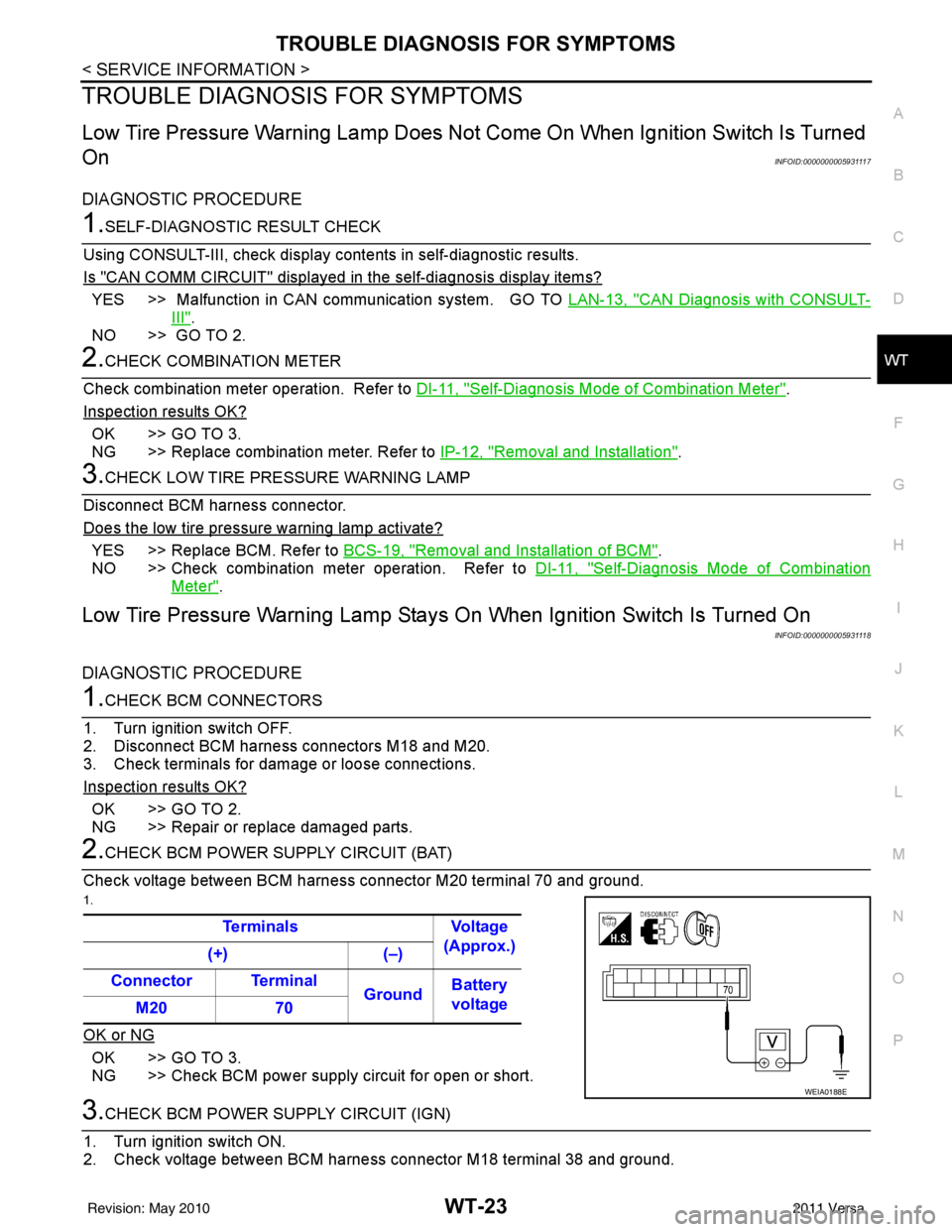
2.CHECK BCM POWER SUPPLY CIRCUIT (BAT)
Check voltage between BCM harness connector M20 terminal 70 and ground.
1.
OK or NG
OK >> GO TO 3.
NG >> Check BCM power supply circuit for open or short.
3.CHECK BCM POWER SUPPLY CIRCUIT (IGN)
1. Turn ignition switch ON.
2. Check voltage between BCM harness connector M18 terminal 38 and ground. Terminals Voltage
(Approx.)
(+) (–)
Connector Terminal GroundBattery
voltage
M20 70
WEIA0188E
Revision: May 2010 2011 Versa
Page 3742 of 3787
WT-24
< SERVICE INFORMATION >
TROUBLE DIAGNOSIS FOR SYMPTOMS
OK or NG
OK >> GO TO 4.
NG >> Check BCM power supply circuit for open or short.
4.CHECK BCM GROUND CIRCUIT
1. Turn ignition switch OFF.
2. Check continuity between BCM harnes s connector M20 terminal 67 and ground.
OK or NG
OK >> Replace BCM. Refer to BCS-19, "Removal and Installa-
tion of BCM".
NG >> Repair BCM ground circuit.
Low Tire Pressure Warning Lamp Flashes When Ignition Switch Is Turned On
INFOID:0000000005931119
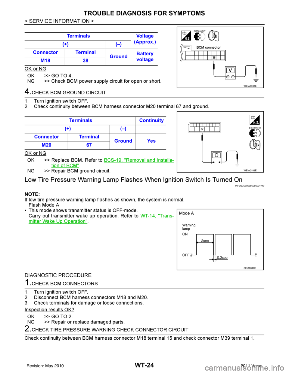
NOTE:
If low tire pressure warning lamp flashes as shown, the system is normal. Flash Mode A
• This mode shows transmitter status is OFF-mode. Carry out transmitter wake up operation. Refer to WT-14, "
Trans-
mitter Wake Up Operation".
DIAGNOSTIC PROCEDURE
1.CHECK BCM CONNECTORS
1. Turn ignition switch OFF.
2. Disconnect BCM harness connectors M18 and M20.
3. Check terminals for damage or loose connections.
Inspection results OK?
OK >> GO TO 2.
NG >> Repair or replace damaged parts.
2.CHECK TIRE PRESSURE WARNING CHECK CONNECTOR CIRCUIT
Check continuity between BCM harness connector M 18 terminal 15 and check connector M39 terminal 1.
Terminals
Voltage
(Approx.)
(+) (–)
Connector Terminal GroundBattery
voltage
M18 38
WEIA0038E
Terminals Continuity
(+) (–)
Connector Terminal Ground Yes
M20 67
WEIA0189E
SEIA0347E
Revision: May 2010 2011 Versa
Page 3744 of 3787
WT-26
< SERVICE INFORMATION >
REMOVAL AND INSTALLATION
REMOVAL AND INSTALLATION
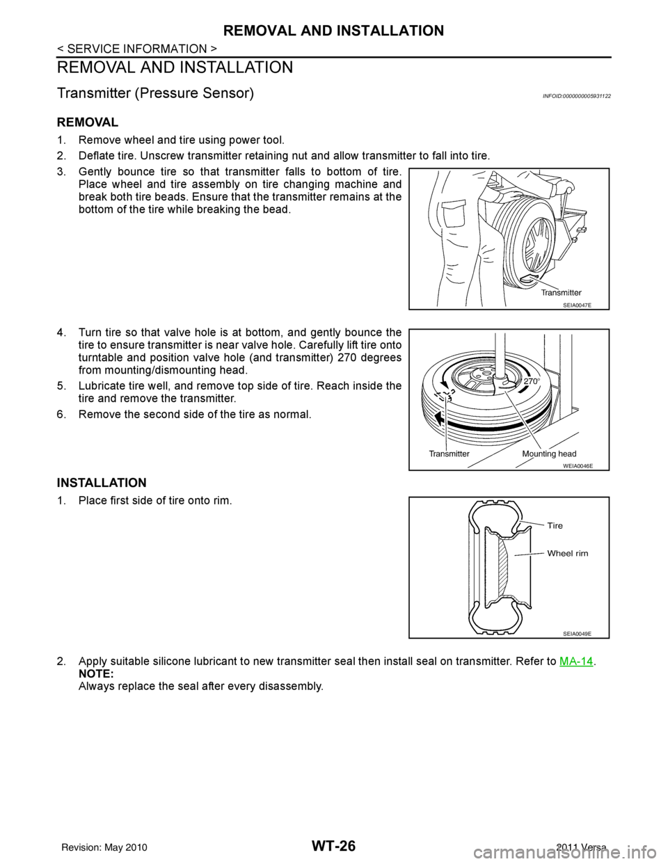
Transmitter (Pressure Sensor)INFOID:0000000005931122
REMOVAL
1. Remove wheel and tire using power tool.
2. Deflate tire. Unscrew transmitter retaining nut and allow transmitter to fall into tire.
3. Gently bounce tire so that trans mitter falls to bottom of tire.
Place wheel and tire assembly on tire changing machine and
break both tire beads. Ensure that the transmitter remains at the
bottom of the tire while breaking the bead.
4. Turn tire so that valve hole is at bottom, and gently bounce the tire to ensure transmitter is near valve hole. Carefully lift tire onto
turntable and position valve hole (and transmitter) 270 degrees
from mounting/dismounting head.
5. Lubricate tire well, and remove top side of tire. Reach inside the tire and remove the transmitter.
6. Remove the second side of the tire as normal.
INSTALLATION
1. Place first side of tire onto rim.
2. Apply suitable silicone lubricant to new transmitter seal then install seal on transmitter. Refer to MA-14
.
NOTE:
Always replace the seal after every disassembly.
SEIA0047E
WEIA0046E
SEIA0049E
Revision: May 2010 2011 Versa
Page 3746 of 3787
WT-28
< SERVICE INFORMATION >
SERVICE DATA AND SPECIFICATIONS (SDS)
SERVICE DATA AND SPECIFICATIONS (SDS)
Road WheelINFOID:0000000005931123
TireINFOID:0000000005931124
Unit: kPa (kg/cm2 , psi)
Standard itemAllowable
Aluminum Steel
Maximum radial runout limit Lateral deflection
Less than 0.3 mm (0.012 in) Less than 0.5 mm (0.020 in)
Radial deflection Less than 0.3 mm (0.012 in) Less than 0.8 mm (0.031 in)
Maximum allowable imbalance Dynamic
(At rim flange)
Less than 5 g (0.18 oz) (one side)
Stati c
(At rim flange) Less than 10 g (0.35 oz)
Tire size Cold tire pressure
Conventional tire Spare ti re
Front wheel Rear wheel
P185/65R14 230 (2.3, 33) 230 (2.3, 33)—
P185/65R15 240 (2.4, 35) 240 (2.4, 35)—
P195/55R16 240 (2.4, 35) 240 (2.4, 35)—
T125/70D15 ——420 (4.2, 60)
Revision: May 2010 2011 Versa