Page 3735 of 3787
TROUBLE DIAGNOSESWT-17
< SERVICE INFORMATION >
C
DF
G H
I
J
K L
M A
B
WT
N
O P
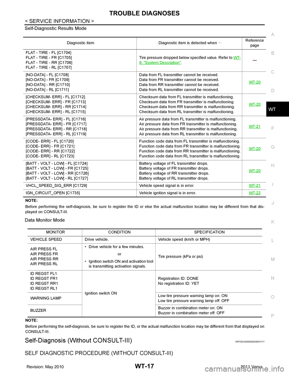
Self-Diagnostic Results Mode
NOTE:
Before performing the self-diagnosis, be sure to register the ID or else the actual malfunction location may be different from
that dis-
played on CONSULT-III.
Data Monitor Mode
NOTE:
Before performing the self-diagnosis, be sure to register the ID, or the actual malfunction location may be different from that displayed on
CONSULT-III.
Self-Diagnosis (Without CONSULT-III)INFOID:0000000005931111
SELF DIAGNOSTIC PROCE DURE (WITHOUT CONSULT-III)
Diagnostic item Diagnostic item is detected when ···Reference
page
FLAT - TIRE - FL [C1704]
FLAT - TIRE - FR [C1705]
FLAT - TIRE - RR [C1706]
FLAT - TIRE - RL [C1707] Tire pressure dropped below specified value. Refer to WT-
9, "System Description".
—
[NO-DATA] - FL [C1708]
[NO-DATA] - FR [C1709]
[NO-DATA] - RR [C1710]
[NO-DATA] - RL [C1711] Data from FL transmitter cannot be received.
Data from FR transmitter cannot be received.
Data from RR transmitter cannot be received.
Data from RL transmitter cannot be received.
WT-20
[CHECKSUM- ERR] - FL [C1712]
[CHECKSUM- ERR] - FR [C1713]
[CHECKSUM- ERR] - RR [C1714]
[CHECKSUM- ERR] - RL [C1715] Checksum data from FL transmitter is malfunctioning.
Checksum data from FR transmitter is malfunctioning.
Checksum data from RR transmitter is malfunctioning.
Checksum data from RL transmitter is malfunctioning.
WT-20
[PRESSDATA- ERR] - FL [C1716]
[PRESSDATA- ERR] - FR [C1717]
[PRESSDATA- ERR] - RR [C1718]
[PRESSDATA- ERR] - RL [C1719] Air pressure data from FL transmitter is malfunctioning.
Air pressure data from FR transmitter is malfunctioning.
Air pressure data from RR transmitter is malfunctioning.
Air pressure data from RL transmitter is malfunctioning.
WT-21
[CODE- ERR] - FL [C1720]
[CODE- ERR] - FR [C1721]
[CODE- ERR] - RR [C1722]
[CODE- ERR] - RL [C1723] Function code data from FL transmitter is malfunctioning.
Function code data from FR transmitter is malfunctioning.
Function code data from RR transmitter is malfunctioning.
Function code data from RL transmitter is malfunctioning.
WT-20
[BATT - VOLT - LOW] - FL [C1724]
[BATT - VOLT - LOW] - FR [C1725]
[BATT - VOLT - LOW] - RR [C1726]
[BATT - VOLT - LOW] - RL [C1727] Battery voltage of FL transmitter drops.
Battery voltage of FR transmitter drops.
Battery voltage of RR transmitter drops.
Battery voltage of RL transmitter drops.
WT-20
VHCL_SPEED_SIG_ERR [C1729]
Vehicle speed signal is in error. WT-21
IGN_CIRCUIT_OPEN [C1735] Vehicle ignition signal is in error. WT-22
MONITORCONDITION SPECIFICATION
VEHICLE SPEED Drive vehicle. Vehicle speed (km/h or MPH)
AIR PRESS FL
AIR PRESS FR
AIR PRESS RR
AIR PRESS RL • Drive vehicle for a few minutes.
Tire pressure (kPa or psi)
or
• Ignition switch ON and activation tool is transmitting activation signals.
ID REGST FL1
ID REGST FR1
ID REGST RR1
ID REGST RL1 Ignition switch ON Registration ID: DONE
No registration ID: YET
WARNING LAMP Low tire pressure
warning lamp on: ON
Low tire pressure warning lamp off: OFF
BUZZER Buzzer in combination meter on: ON
Buzzer in combination meter off: OFF
Revision: May 2010
2011 Versa
Page 3761 of 3787
FRONT WIPER AND WASHER SYSTEMWW-15
< SERVICE INFORMATION >
C
DE
F
G H
I
J
L
M A
B
WW
N
O P
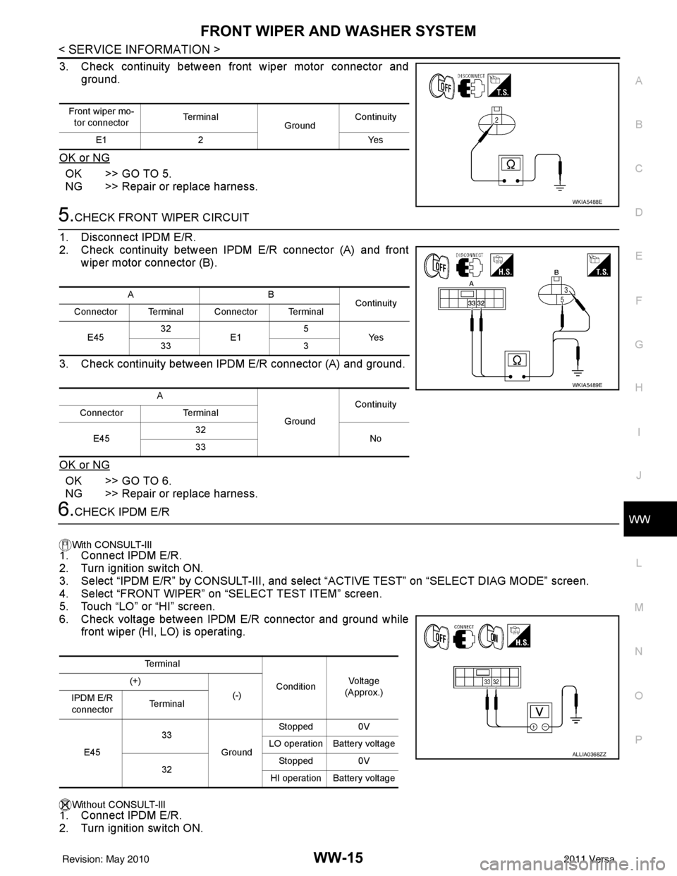
3. Check continuity between front wiper motor connector and ground.
OK or NG
OK >> GO TO 5.
NG >> Repair or replace harness.
5.CHECK FRONT WIPER CIRCUIT
1. Disconnect IPDM E/R.
2. Check continuity between IPDM E/R connector (A) and front wiper motor connector (B).
3. Check continuity between IPDM E/R connector (A) and ground.
OK or NG
OK >> GO TO 6.
NG >> Repair or replace harness.
6.CHECK IPDM E/R
With CONSULT-lIl
1. Connect IPDM E/R.
2. Turn ignition switch ON.
3. Select “IPDM E/R” by CONSULT-III, and sele ct “ACTIVE TEST” on “SELECT DIAG MODE” screen.
4. Select “FRONT WIPER” on “SELECT TEST ITEM” screen.
5. Touch “LO” or “HI” screen.
6. Check voltage between IPDM E/R connector and ground while front wiper (HI, LO) is operating.
Without CONSULT-llI
1. Connect IPDM E/R.
2. Turn ignition switch ON.
Front wiper mo-
tor connector Te r m i n a l
GroundContinuity
E1 2 Yes
WKIA5488E
AB
Continuity
Connector Terminal Connector Terminal
E45 32
E1 5
Ye s
33 3
A GroundContinuity
Connector Terminal
E45 32
No
33
WKIA5489E
Te r m i n a l
ConditionVo l ta g e
(Approx.)
(+)
(-)
IPDM E/R
connector Te r m i n a l
E45 33
GroundStopped 0V
LO operation Battery voltage
32 Stopped 0V
HI operation Battery voltage
ALLIA0368ZZ
Revision: May 2010 2011 Versa
Page 3778 of 3787
WW-32
< SERVICE INFORMATION >
REAR WIPER AND WASHER SYSTEM
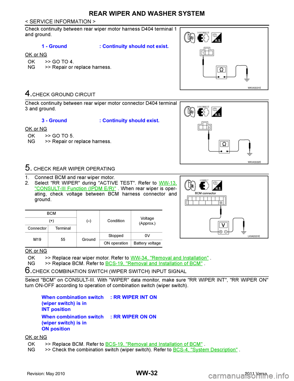
Check continuity between rear wiper motor harness D404 terminal 1
and ground.
OK or NG
OK >> GO TO 4.
NG >> Repair or replace harness.
4.CHECK GROUND CIRCUIT
Check continuity between rear wiper motor connector D404 terminal
3 and ground.
OK or NG
OK >> GO TO 5.
NG >> Repair or replace harness.
5. CHECK REAR WIPER OPERATING
1. Connect BCM and rear wiper motor.
2. Select "RR WIPER" during "ACTIVE TEST". Refer to WW-13,
"CONSULT-III Function (IPDM E/R)" . When rear wiper is oper-
ating, check voltage between BCM harness connector and
ground.
OK or NG
OK >> Replace rear wiper motor. Refer to WW-34, "Removal and Installation" .
NG >> Replace BCM. Refer to BCS-19, "
Removal and Installation of BCM" .
6.CHECK COMBINATION SWITCH (W IPER SWITCH) INPUT SIGNAL
Select "BCM" on CONSULT-III. With "WIPER" data monitor, make sure "RR WIPER INT", "RR WIPER ON"
turn ON-OFF according to operation of combination switch (wiper switch).
OK or NG
OK >> Replace BCM. Refer to BCS-19, "Removal and Installation of BCM" .
NG >> Check the combination switch (wiper switch). Refer to BCS-4, "
System Description" .
1 - Ground
: Continuity should not exist.
WKIA5531E
3 - Ground : Continuity should exist.
WKIA5532E
BCM
(–) Condition Vol tag e
(Approx.)
(+)
Connector Terminal
M19 55 Ground Stopped
0V
ON operation Battery voltage
LKIA0551E
When combination switch
(wiper switch) is in
INT position : RR WIPER INT ON
When combination switch
(wiper switch) is in
ON position : RR WIPER ON ON
Revision: May 2010
2011 Versa