2011 NISSAN LATIO trunk
[x] Cancel search: trunkPage 650 of 3787

BL-140
< SERVICE INFORMATION >
INTELLIGENT KEY SYSTEM
4.CHECK TRUNK OPENER REQUEST SWITCH GROUND CIRCUIT
Check continuity between trunk opener request switch connector B129 terminal 2 and ground.
OK or NG
OK >> GO TO 5
NG >> Repair or replace trunk opener request switch ground circuit.
5.CHECK INTELLIGENT KEY UNIT OUTPUT SIGNAL
1. Connect Intelligent Key unit connector.
2. Check voltage between Intelligent Key unit connector M52 terminal 29 and ground.
OK or NG
OK >> Check the condition of harness and connector.
NG >> Replace Intelligent Key unit. Refer to BL-158, "
Removal
and Installation of Intelligent Key Unit".
Unlock Sensor CheckINFOID:0000000005929351
1.CHECK UNLOCK SENSOR INPUT SIGNAL
Check voltage between Intelligent Key unit connector and ground.
OK or NG
OK >> Unlock sensor circuit is OK.
NG >> GO TO 2
2.CHECK UNLOCK SENSOR CIRCUIT
Trunk opener request switch connector Te r m i n a l
GroundContinuity
B129 2 Yes
PIIB6337E
Te r m i n a l s
Voltage (V)(Approx.)
(+)
(–)
Intelligent Key unit
connector Te r m i n a l
M52 29Ground 5
PIIB6617E
Te r m i n a l s
Front door
lock
(driver side) condition Voltage (V)
(Approx.)
(+)
(–)
Intelligent Key
unit connector Te r m i n a l
M52 28Ground Locked
5
Unlocked 0
PIIB6638E
Revision: May 2010 2011 Versa
Page 652 of 3787
BL-142
< SERVICE INFORMATION >
INTELLIGENT KEY SYSTEM
OK or NG
OK >> Replace front door lock assembly LH (door unlock sen-sor). Refer to BL-167, "
Removal and Installation".
NG >> Replace Intelligent Key unit. Refer to BL-158, "
Removal
and Installation of Intelligent Key Unit".
Intelligent Key Warning Buzzer(s) CheckINFOID:0000000005929352
1.CHECK INTELLIGENT KEY WARNING BUZZER POWER SUPPLY CIRCUIT
1. Disconnect inoperative Intelligent Key warning buzzer connector.
2. Check voltage between Intelligent Key warning buzzer connector and ground.
OK or NG
OK >> GO TO 2
NG >> Repair or replace Intelligent Key warning buzzer power supply circuit.
2.CHECK INTELLIGENT KEY WARNING BUZZER CIRCUIT
1. Disconnect Intelligent Key unit connector.
2. Check continuity between Intelligent Key unit c onnector and inoperative Intelligent Key warning buzzer
connector.
3. Check continuity between Intelligent Key unit connector and ground.
OK or NG
OK >> GO TO 3
NG >> Repair or replace harness between Intelligent Key unit and Intelligent Key warning buzzer.
3.CHECK INTELLIGENT KEY WA RNING BUZZER OPERATION
Connect battery power supply to Intelligent Key warning buzzer terminals 1 and 2, and check the operation.
Te r m i n a l s
Voltage (V)(Approx.)
(+)
(–)
Intelligent Key unit
connector Te r m i n a l
M52 28Ground 5
PIIB6638E
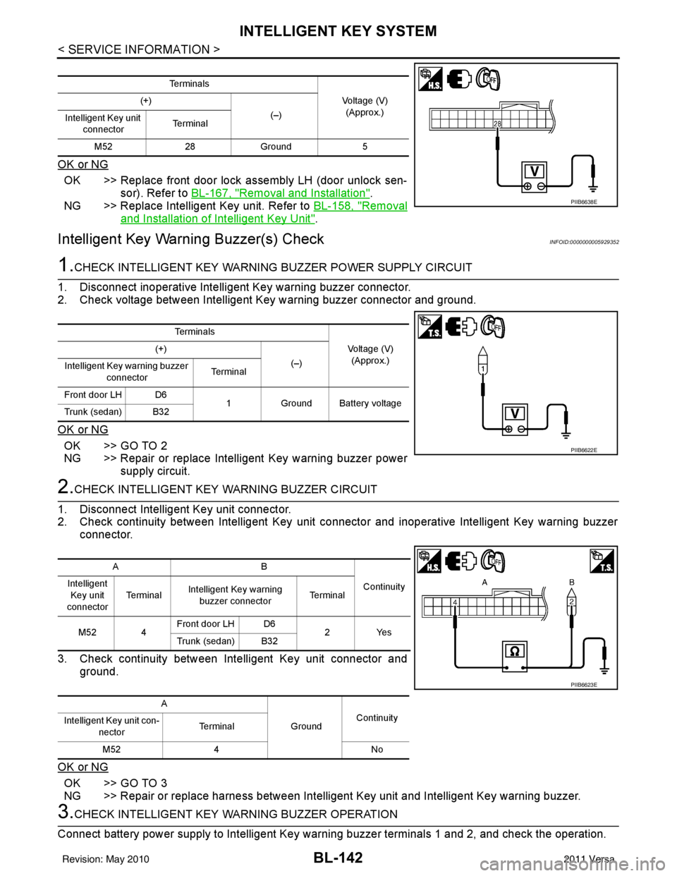
Te r m i n a l s
Voltage (V)(Approx.)
(+)
(–)
Intelligent Key warning buzzer
connector Te r m i n a l
Front door LH D6 1Ground Battery voltage
Trunk (sedan) B32
PIIB6622E
AB
Continuity
Intelligent
Key unit
connector Te r m i n a l
Intelligent Key warning
buzzer connector Te r m i n a l
M52 4 Front door LH D6
2Yes
Trunk (sedan) B32
A GroundContinuity
Intelligent Key unit con-
nector Terminal
M52 4 No
PIIB6623E
Revision: May 2010 2011 Versa
Page 688 of 3787
BL-178
< SERVICE INFORMATION >
BACK DOOR LOCK
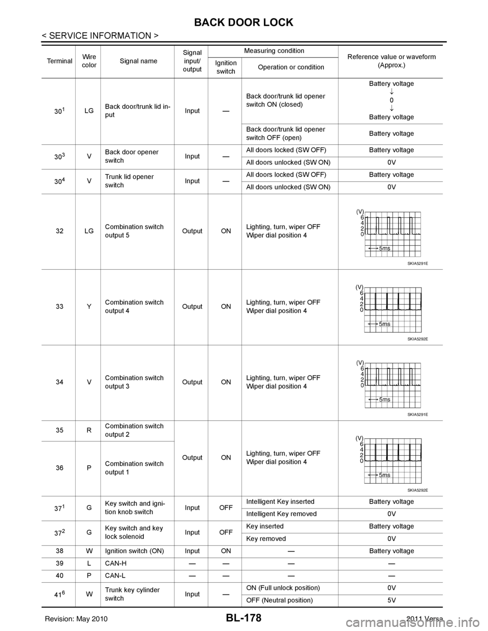
301LGBack door/trunk lid in-
put Input —Back door/trunk lid opener
switch ON (closed) Battery voltage
↓0
↓
Battery voltage
Back door/trunk lid opener
switch OFF (open) Battery voltage
30
3V Back door opener
switch
Input —All doors locked (SW OFF)
Battery voltage
All doors unlocked (SW ON) 0V
30
4V Trunk lid opener
switch
Input —All doors locked (SW OFF)
Battery voltage
All doors unlocked (SW ON) 0V
32 LG Combination switch
output 5 Output ONLighting, turn, wiper OFF
Wiper dial position 4
33 Y Combination switch
output 4 Output ON
Lighting, turn, wiper OFF
Wiper dial position 4
34 V Combination switch
output 3
Output ONLighting, turn, wiper OFF
Wiper dial position 4
35 R Combination switch
output 2
Output ONLighting, turn, wiper OFF
Wiper dial position 4
36 P Combination switch
output 1
37
1G Key switch and igni-
tion knob switch Input OFFIntelligent Key inserted
Battery voltage
Intelligent Key removed 0V
37
2G Key switch and key
lock solenoid Input OFFKey inserted
Battery voltage
Key removed 0V
38 W Ignition switch (ON) Input ON —Battery voltage
39 L CAN-H — —— —
40 P CAN-L — —— —
41
6W Trunk key cylinder
switch
Input —ON (Full unlock position)
0V
OFF (Neutral position) 5V
Te r m i n a l
Wire
color Signal name Signal
input/
output Measuring condition
Reference value or waveform
(Approx.)
Ignition
switch Operation or condition
SKIA5291E
SKIA5292E
SKIA5291E
SKIA5292E
Revision: May 2010
2011 Versa
Page 689 of 3787

BACK DOOR LOCKBL-179
< SERVICE INFORMATION >
C
DE
F
G H
J
K L
M A
B
BL
N
O P
426Y Trunk lamp switch Input OFF ON (trunk open)
0V
OFF (trunk closed) Battery voltage
43
5R Back door switch Input OFF ON (open) 0V
OFF (closed)
Battery voltage
44
5LG Rear wiper auto stop Input ON Rear wiper operating 0
Rear wiper stopped
Battery
45
7GR Lock switch Input OFFON (lock)
0V
OFF Battery voltage
46
7L Unlock switch Input OFFON (unlock)
0V
OFF Battery voltage
47 BR Front door switch LH Input OFF ON (open)
0V
OFF (closed) Battery voltage
48 O Rear door switch LH Input OFF ON (open)
0V
OFF (closed) Battery voltage
49 P Luggage room lamp Output OFF Any door open (ON)
0V
All doors closed (OFF) Battery voltage
50 SB A/C indicator Output ONA/C OFF
0
A/C ON Battery voltage
53
5R Back door lock assem-
bly (actuator)
Output OFF Back door (open)
Battery voltage
53
6R Trunk lamp switch and
trunk release solenoid Output OFF Trunk lid (open)
Battery voltage
55
5V Rear wiper motor out-
put
Output ONOFF
0
ON Battery voltage
56 R Battery saver output Output OFF
15 minutes after ignition
switch is turned OFF 0V
ON — Battery voltage
57 LG Battery power supply Input OFF —Battery voltage
59
7G Front door lock actua-
tor LH (unlock)
Output OFFOFF (neutral)
0V
ON (unlock) Battery voltage
60 V Turn signal (left) Output ON Turn left ON
61 W Turn signal (right) Output ON Turn right ON
Te r m i n a l
Wire
color Signal name Signal
input/
output Measuring condition
Reference value or waveform
(Approx.)
Ignition
switch Operation or condition
SKIA3009J
SKIA3009J
Revision: May 2010
2011 Versa
Page 692 of 3787

BL-182
< SERVICE INFORMATION >
BACK DOOR LOCK
*1: With continuously variable transmission (CVT) or automatic transmission (A/T).
*2: With manual transmission (M/T).
CONSULT-III Function (BCM)INFOID:0000000005929384
CONSULT-III can display each diagnostic item us ing the diagnostic test modes shown following.
28 YUnlock sensor
(driver side) —Door (driver si
de) is locked. 5
Door (driver side ) is unlocked. 0
29 V Back door request
switch (hatchback)
—Press back door request switch.
0
Other than above 5
Trunk opener request
switch (sedan) —Press trunk opener request switch.
0
Other than above 5
31 BR Steering lock solenoid
ground ——
0
32 GR Steering lock solenoid
communication signal LOCKWhen Intelligent Key is inside vehicle,
press ignition knob switch.
Other than above
5
33 R Rear floor antenna (+)
signal
LOCK• Any door open
→ all door close
• Press ignition knob switch: ON (Ignition
knob switch)
34 G Rear floor antenna (-)
signal
37 BR Front outside antenna
RH (+) signal
LOCK Press door request switch RH.
38 Y Front outside antenna
RH (-) signal
Te r m i n a l
Wire
Color Item Condition
Voltage (V)Approx.
Ignition
Switch
Position Operation or Conditions
SIIA1911J
PIIB5502J
SIIA1910J
Diagnostic mode
Description
WORK SUPPORT Supports inspections and adjustments. Commands are transmitted to the BCM for setting the status
suitable for required operation, input/output signals are received from the BCM and received date
is displayed.
DATA MONITOR Displays BCM input/output data in real time. ACTIVE TEST Operation of electrical loads can be checked by sending drive signal to them.
SELF DIAGNOSTIC RESULT Displays BCM self-diagnosis results.
CAN DIAG SUPPORT MNTR The result of transmit/receive diagnosis of CAN communication can be read. ECU IDENTIFICATION BCM part number can be read.CONFIGURATION Performs BCM configuration read/write functions.
Revision: May 2010 2011 Versa
Page 693 of 3787
BACK DOOR LOCKBL-183
< SERVICE INFORMATION >
C
DE
F
G H
J
K L
M A
B
BL
N
O P
CONSULT-III APPLICATION ITEMS
Data Monitor
Active Test
Work FlowINFOID:0000000005929385
1. Check the symptom and customer's requests.
2. Understand the outline of system. Refer to BL-173, "
System Description".
3. Repair or replace any malfunctioning parts. Refer to BL-183, "
Trouble Diagnosis Chart by Symptom".
4. Does back door opener operate normally? If Yes, GO TO 5. If No, GO TO 3.
5. Inspection End.
Trouble Diagnosis Chart by SymptomINFOID:0000000005929386
BCM Power Supply and Gr ound Circuit InspectionINFOID:0000000006215774
1.CHECK FUSES AND FUSIBLE LINK
• Check 40A fusible link (letter g , located in the fuse and fusible link box).
• Check 10A fuses [No. 6, 8 and 20, lo cated in the fuse block (J/B)].
OK or NG
OK >> GO TO 2.
Monitor item Content
IGN ON SW Indicates [ON/OFF] condition of ignition switch.
TRNK OPNR SW Indicates [ON/OFF] condition of back door open signal from back door opener switch.
VEHICLE SPEED Indicates [km/h] condition of vehicle speed.
Test item Content
TRUNK/BACK DOOR This test checks back door lock assembly operation.
Back door opens when “Open” is selected.
Symptom
Diagnoses/service procedureReference
page
Back door opener does not operate.
(Without Intelligent Key or power windows) 1. Check BCM power supply and ground circuit.
BCS-16
2. Check back door opener switch circuit. BL-184
3. Check back door lock assembly (actuator) circuit.BL-191
4. Replace BCM.BCS-19
Back door opener does not operate.
(Without Intelligent Key, with power windows)1. Check BCM power supply and ground circuit.
BCS-162. Check back door opener switch circuit. BL-187
3. Check back door lock assembly (actuator) circuit.BL-191
4. Replace BCM.BCS-19
Back door opener does not operate.
(With Intelligent Key)1. Check BCM power supply and ground circuit.
BCS-16
2.Check Intelligent Key power supply and ground cir-
cuit.
BL-126
3. Check back door opener switch circuit.
BL-189
4. Check back door lock assembly (actuator) circuit.BL-191
5. Replace BCM.BCS-19
Revision: May 2010 2011 Versa
Page 702 of 3787
BL-192
< SERVICE INFORMATION >
BACK DOOR LOCK
Check the operation with (“TRUNK/BACK DOOR”) in the ACTIVE TEST.
YES or NO
YES >> Back door lock assembly (actuator) is OK.
NO >> GO TO 2
2.CHECK BACK DOOR LOCK ASSEMBLY (ACTUATOR) POWER SUPPLY
1. Turn ignition switch OFF.
2. Insure both front door lock knobs are turned to the UNLOCK position.
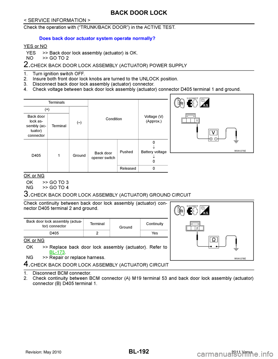
3. Disconnect back door lock assembly (actuator) connector.
4. Check voltage between back door lock assembly (actuator) connector D405 terminal 1 and ground.
OK or NG
OK >> GO TO 3
NG >> GO TO 4
3.CHECK BACK DOOR LOCK ASSEMB LY (ACTUATOR) GROUND CIRCUIT
Check continuity between back door lock assembly (actuator) con-
nector D405 terminal 2 and ground.
OK or NG
OK >> Replace back door lock assembly (actuator). Refer to BL-173
.
NG >> Repair or replace harness.
4.CHECK BACK DOOR LOCK A SSEMBLY (ACTUATOR) CIRCUIT
1. Disconnect BCM connector.
2. Check continuity between BCM connector (A) M19 te rminal 53 and back door lock assembly (actuator)
connector (B) D405 terminal 1. Does back door actuator system operate normally?
Te r m i n a l s
ConditionVoltage (V)
(Approx.)
(+)
(–)
Back door
lock as-
sembly (ac-
tuator)
connector Te r m i n a l
D405 1 Ground Back door
opener switch Pushed 0
↓
Battery voltage ↓0
Released 0
WIIA1275E
Back door lock assembly (actua- tor) connector Te r m i n a l
GroundContinuity
D405 2 Yes
WIIA1276E
Revision: May 2010 2011 Versa
Page 705 of 3787
TRUNK LIDBL-195
< SERVICE INFORMATION >
C
DE
F
G H
J
K L
M A
B
BL
N
O P
TRUNK LID
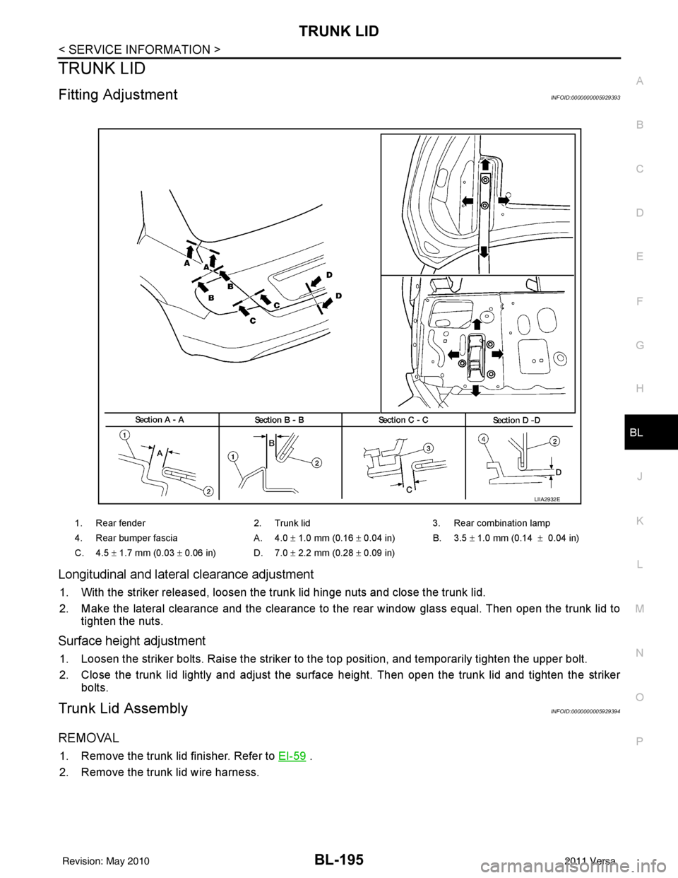
Fitting AdjustmentINFOID:0000000005929393
Longitudinal and latera l clearance adjustment
1. With the striker released, loosen the trunk lid hinge nuts and close the trunk lid.
2. Make the lateral clearance and the clearance to the rear window glass equal. Then open the trunk lid to
tighten the nuts.
Surface height adjustment
1. Loosen the striker bolts. Raise the striker to t he top position, and temporarily tighten the upper bolt.
2. Close the trunk lid lightly and adjust the surface height. Then open the trunk lid and tighten the striker bolts.
Trunk Lid AssemblyINFOID:0000000005929394
REMOVAL
1. Remove the trunk lid finisher. Refer to EI-59 .
2. Remove the trunk lid wire harness.
1. Rear fender 2. Trunk lid3. Rear combination lamp
4. Rear bumper fascia A. 4.0 ± 1.0 mm (0.16 ± 0.04 in) B. 3.5 ± 1.0 mm (0.14 ± 0.04 in)
C. 4.5 ± 1.7 mm (0.03 ± 0.06 in) D. 7.0 ± 2.2 mm (0.28 ± 0.09 in)
LIIA2932E
Revision: May 2010 2011 Versa