2011 NISSAN LATIO oil filter
[x] Cancel search: oil filterPage 1921 of 3787
TROUBLE DIAGNOSIS - SPECIFICATION VALUEEC-627
< SERVICE INFORMATION > [MR18DE]
C
D
E
F
G H
I
J
K L
M A
EC
NP
O
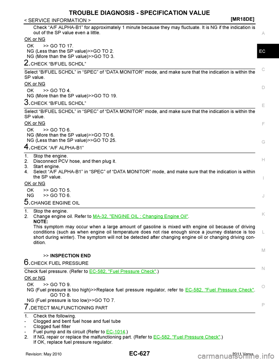
Check “A/F ALPHA-B1” for approximately 1 minute because t
hey may fluctuate. It is NG if the indication is
out of the SP value even a little.
OK or NG
OK >> GO TO 17.
NG (Less than the SP value)>>GO TO 2.
NG (More than the SP value)>>GO TO 3.
2.CHECK “B/FUEL SCHDL”
Select “B/FUEL SCHDL” in “SPEC” of “DATA MONITOR” m ode, and make sure that the indication is within the
SP value.
OK or NG
OK >> GO TO 4.
NG (More than the SP value)>>GO TO 19.
3.CHECK “B/FUEL SCHDL”
Select “B/FUEL SCHDL” in “SPEC” of “DATA MONITOR” m ode, and make sure that the indication is within the
SP value.
OK or NG
OK >> GO TO 6.
NG (More than the SP value)>>GO TO 6.
NG (Less than the SP value)>>GO TO 25.
4.CHECK “A/F ALPHA-B1”
1. Stop the engine.
2. Disconnect PCV hose, and then plug it.
3. Start engine.
4. Select “A/F ALPHA-B1” in “SPEC” of “DATA MONITOR” mode, and make sure that the indication is within
the SP value.
OK or NG
OK >> GO TO 5.
NG >> GO TO 6.
5.CHANGE ENGINE OIL
1. Stop the engine.
2. Change engine oil. Refer to MA-32, "
ENGINE OIL : Changing Engine Oil".
NOTE:
This symptom may occur when a large amount of gas oline is mixed with engine oil because of driving
conditions (such as when engine oil temperature does not rise enough since a journey distance is too
short during winter). The symptom will not be detect ed after changing engine oil or changing driving con-
dition.
>>INSPECTION END
6.CHECK FUEL PRESSURE
Check fuel pressure. (Refer to EC-582, "
Fuel Pressure Check".)
OK or NG
OK >> GO TO 9.
NG (Fuel pressure is too high)>>Replace fuel pressure regulator, refer to EC-582, "
Fuel Pressure Check".
GO TO 8.
NG (Fuel pressure is too low)>>GO TO 7.
7.DETECT MALFUNCTIONING PART
1. Check the following.
- Clogged and bent fuel hose and fuel tube
- Clogged fuel filter
- Fuel pump and its circuit (Refer to EC-1014
.)
2. If NG, repair or replace the malfunctioning part. (Refer to EC-582, "
Fuel Pressure Check".)
If OK, replace fuel pressure regulator.
Revision: May 2010 2011 Versa
Page 2080 of 3787
EC-786
< SERVICE INFORMATION >[MR18DE]
DTC P0300 - P0304 MULTIPLE CYLINDER
MISFIRE, NO. 1 - 4 CYLINDER MIS-
FIRE
3. Crank engine for about 3 seconds, and recheck whether spark is generated between the spark plug and
the grounded metal portion.
OK or NG
OK >> GO TO 7.
NG >> Check ignition coil, power transistor and their circuits. Refer to EC-1019
.
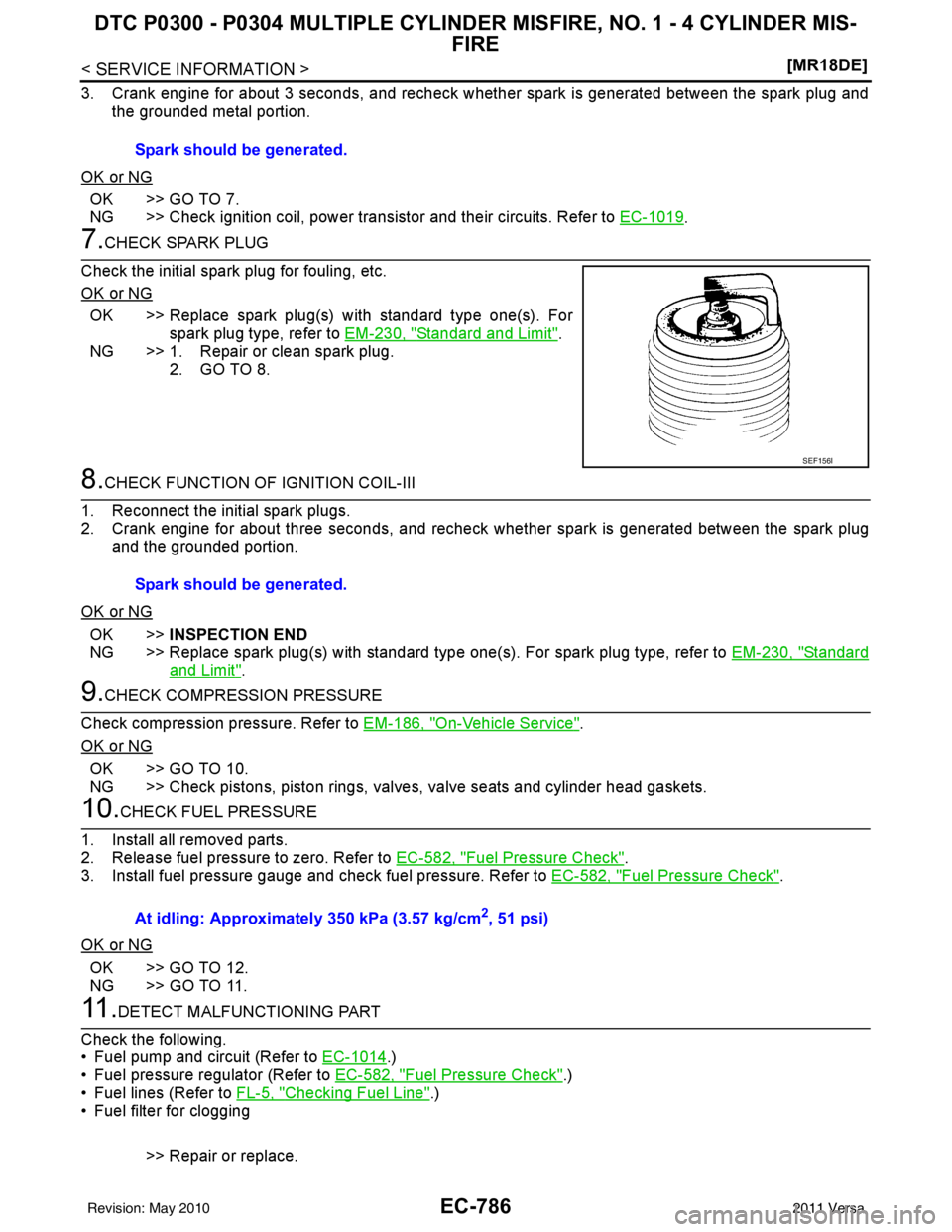
7.CHECK SPARK PLUG
Check the initial spark plug for fouling, etc.
OK or NG
OK >> Replace spark plug(s) with standard type one(s). For spark plug type, refer to EM-230, "
Standard and Limit".
NG >> 1. Repair or clean spark plug. 2. GO TO 8.
8.CHECK FUNCTION OF IGNITION COIL-III
1. Reconnect the initial spark plugs.
2. Crank engine for about three seconds, and recheck whether spark is generated between the spark plug
and the grounded portion.
OK or NG
OK >> INSPECTION END
NG >> Replace spark plug(s) with standard type one(s). For spark plug type, refer to EM-230, "
Standard
and Limit".
9.CHECK COMPRESSION PRESSURE
Check compression pressure. Refer to EM-186, "
On-Vehicle Service".
OK or NG
OK >> GO TO 10.
NG >> Check pistons, piston rings, valves, valve seats and cylinder head gaskets.
10.CHECK FUEL PRESSURE
1. Install all removed parts.
2. Release fuel pressure to zero. Refer to EC-582, "
Fuel Pressure Check".
3. Install fuel pressure gauge and check fuel pressure. Refer to EC-582, "
Fuel Pressure Check".
OK or NG
OK >> GO TO 12.
NG >> GO TO 11.
11 .DETECT MALFUNCTIONING PART
Check the following.
• Fuel pump and circuit (Refer to EC-1014
.)
• Fuel pressure regulator (Refer to EC-582, "
Fuel Pressure Check".)
• Fuel lines (Refer to FL-5, "
Checking Fuel Line".)
• Fuel filter for clogging
>> Repair or replace.
Spark should be generated.
SEF156I
Spark should be generated.
At idling: Approximately 350 kPa (3.57 kg/cm
2, 51 psi)
Revision: May 2010
2011 Versa
Page 2130 of 3787
EC-836
< SERVICE INFORMATION >[MR18DE]
DTC P0447 EVAP CANISTER VENT CONTROL VALVE
DTC P0447 EVAP CANISTER VENT CONTROL VALVE
Component DescriptionINFOID:0000000006342001
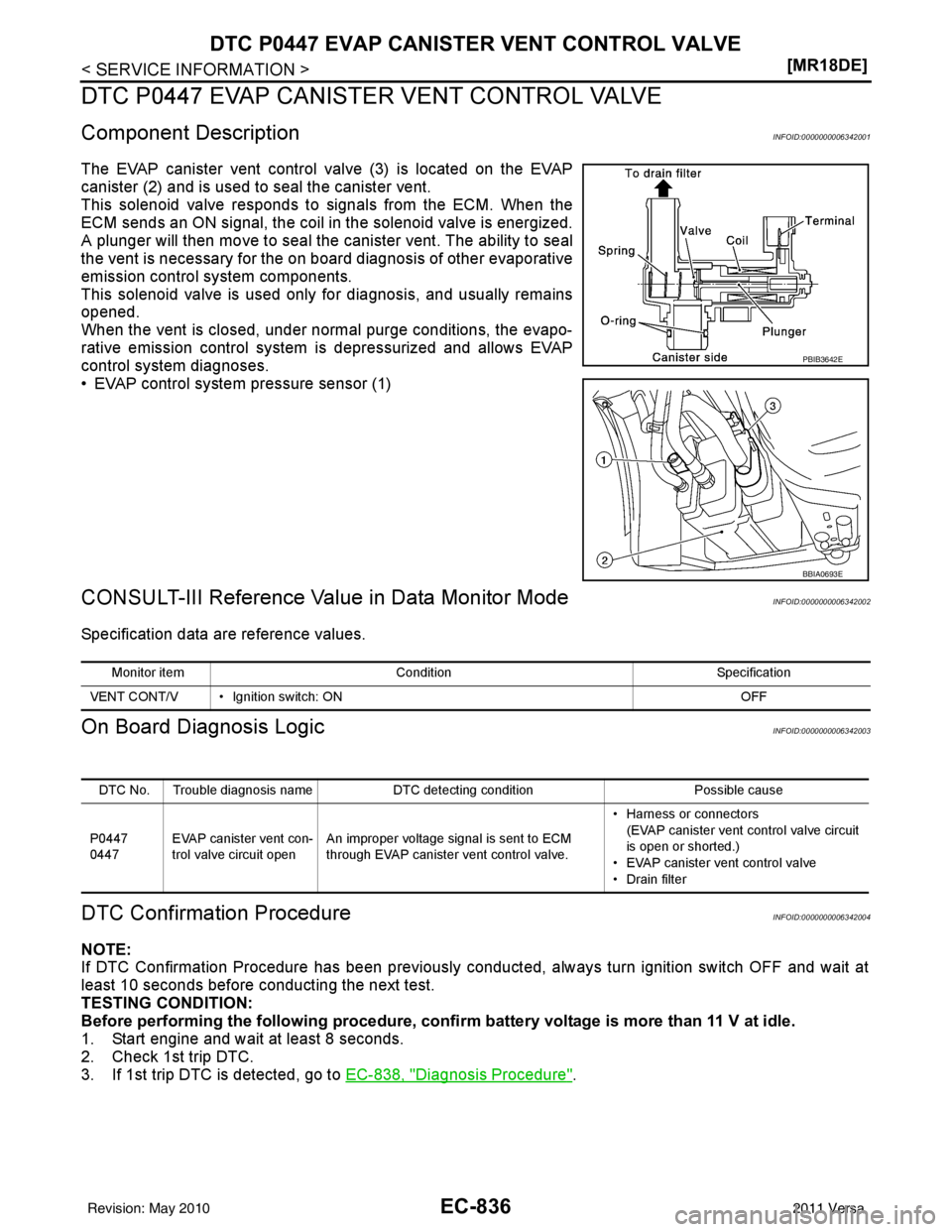
The EVAP canister vent control valve (3) is located on the EVAP
canister (2) and is used to seal the canister vent.
This solenoid valve responds to signals from the ECM. When the
ECM sends an ON signal, the coil in the solenoid valve is energized.
A plunger will then move to seal the canister vent. The ability to seal
the vent is necessary for the on board diagnosis of other evaporative
emission control system components.
This solenoid valve is used only for diagnosis, and usually remains
opened.
When the vent is closed, under normal purge conditions, the evapo-
rative emission control system is depressurized and allows EVAP
control system diagnoses.
• EVAP control system pressure sensor (1)
CONSULT-III Reference Value in Data Monitor ModeINFOID:0000000006342002
Specification data are reference values.
On Board Diagn
osis LogicINFOID:0000000006342003
DTC Confirmation ProcedureINFOID:0000000006342004
NOTE:
If DTC Confirmation Procedure has been previously conducted, always turn ignition switch OFF and wait at
least 10 seconds before conducting the next test.
TESTING CONDITION:
Before performing the following procedure, confi rm battery voltage is more than 11 V at idle.
1. Start engine and wait at least 8 seconds.
2. Check 1st trip DTC.
3. If 1st trip DTC is detected, go to EC-838, "
Diagnosis Procedure".
PBIB3642E
BBIA0693E
Monitor item Condition Specification
VENT CONT/V • Ignition switch: ON OFF
DTC No. Trouble diagnosis nameDTC detecting condition Possible cause
P0447
0447 EVAP canister vent con-
trol valve circuit open An improper voltage signal is sent to ECM
through EVAP canister vent control valve. • Harness or connectors
(EVAP canister vent control valve circuit
is open or shorted.)
• EVAP canister vent control valve
• Drain filter
Revision: May 2010 2011 Versa
Page 2136 of 3787
EC-842
< SERVICE INFORMATION >[MR18DE]
DTC P0448 EVAP CANISTER VENT CONTROL VALVE
DTC P0448 EVAP CANISTER VENT CONTROL VALVE
Component DescriptionINFOID:0000000006342008
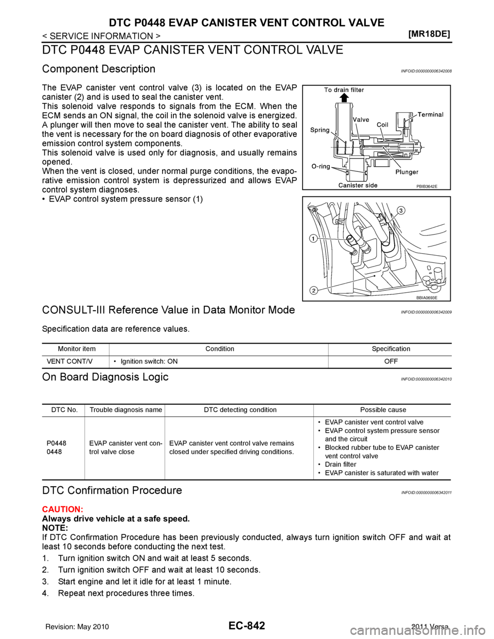
The EVAP canister vent control valve (3) is located on the EVAP
canister (2) and is used to seal the canister vent.
This solenoid valve responds to signals from the ECM. When the
ECM sends an ON signal, the coil in the solenoid valve is energized.
A plunger will then move to seal the canister vent. The ability to seal
the vent is necessary for the on board diagnosis of other evaporative
emission control system components.
This solenoid valve is used only for diagnosis, and usually remains
opened.
When the vent is closed, under normal purge conditions, the evapo-
rative emission control system is depressurized and allows EVAP
control system diagnoses.
• EVAP control system pressure sensor (1)
CONSULT-III Reference Value in Data Monitor ModeINFOID:0000000006342009
Specification data are reference values.
On Board Diagn
osis LogicINFOID:0000000006342010
DTC Confirmation ProcedureINFOID:0000000006342011
CAUTION:
Always drive vehicle at a safe speed.
NOTE:
If DTC Confirmation Procedure has been previously conducted, always turn ignition switch OFF and wait at
least 10 seconds before conducting the next test.
1. Turn ignition switch ON and wait at least 5 seconds.
2. Turn ignition switch OFF and wait at least 10 seconds.
3. Start engine and let it idle for at least 1 minute.
4. Repeat next procedures three times.
PBIB3642E
BBIA0693E
Monitor item Condition Specification
VENT CONT/V • Ignition switch: ON OFF
DTC No. Trouble diagnosis nameDTC detecting condition Possible cause
P0448
0448 EVAP canister vent con-
trol valve close EVAP canister vent control valve remains
closed under specified driving conditions. • EVAP canister vent control valve
• EVAP control system pressure sensor
and the circuit
• Blocked rubber tube to EVAP canister
vent control valve
• Drain filter
• EVAP canister is saturated with water
Revision: May 2010 2011 Versa
Page 2391 of 3787
EM-1
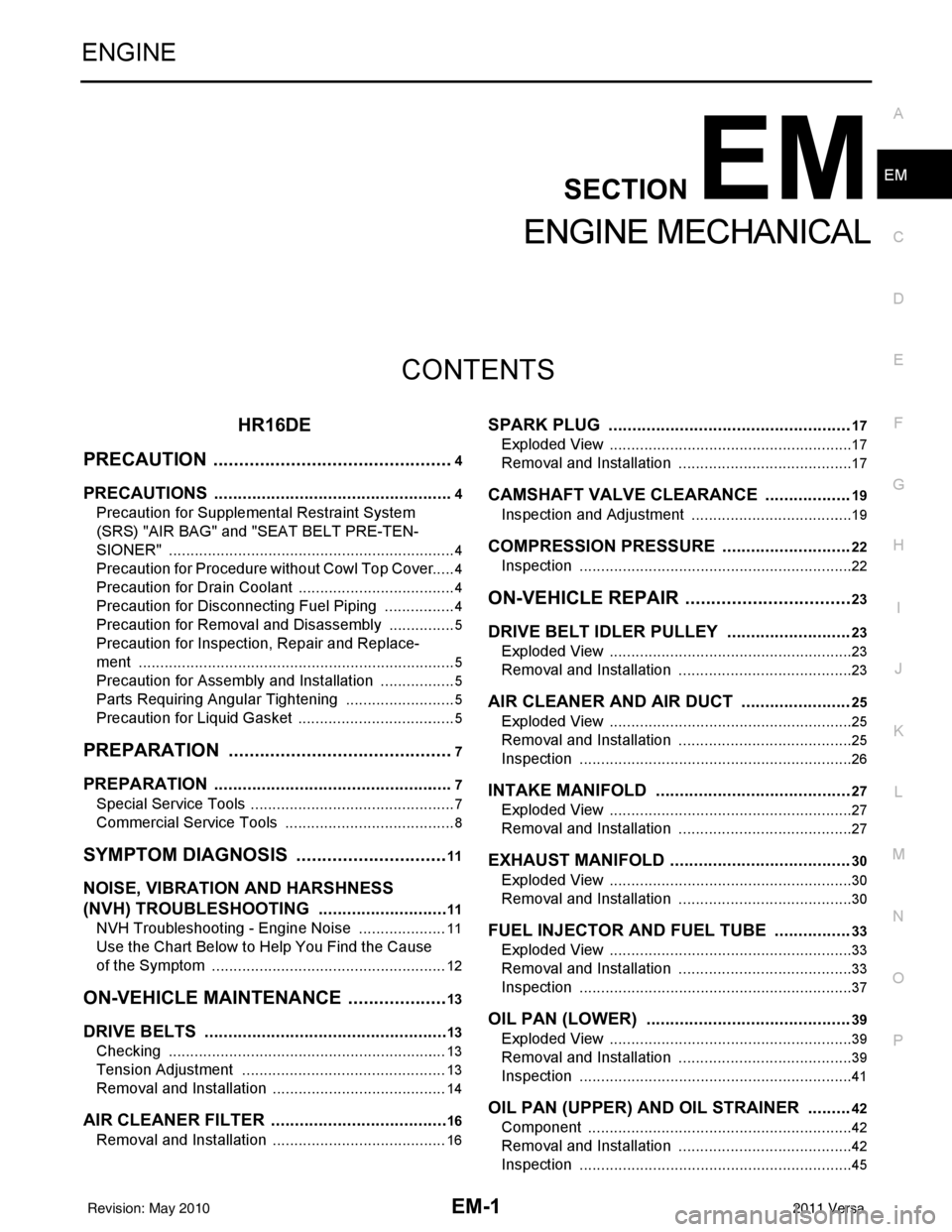
ENGINE
C
DE
F
G H
I
J
K L
M
SECTION EM
A
EM
N
O P
CONTENTS
ENGINE MECHANICAL
HR16DE
PRECAUTION ....... ........................................
4
PRECAUTIONS .............................................. .....4
Precaution for Supplemental Restraint System
(SRS) "AIR BAG" and "SEAT BELT PRE-TEN-
SIONER" ............................................................. ......
4
Precaution for Procedure without Cowl Top Cover ......4
Precaution for Drain Coolant .....................................4
Precaution for Disconnecting Fuel Piping ........... ......4
Precaution for Removal and Disassembly ................5
Precaution for Inspection, Repair and Replace-
ment .................................................................... ......
5
Precaution for Assembly and Installation ..................5
Parts Requiring Angular Tightening ..........................5
Precaution for Liquid Gasket ............................... ......5
PREPARATION ............................................7
PREPARATION .............................................. .....7
Special Service Tools .......................................... ......7
Commercial Service Tools ........................................8
SYMPTOM DIAGNOSIS ..............................11
NOISE, VIBRATION AND HARSHNESS
(NVH) TROUBLESHOOTING ........................ ....
11
NVH Troubleshooting - Engine Noise ................. ....11
Use the Chart Below to Help You Find the Cause
of the Symptom .......................................................
12
ON-VEHICLE MAINTENANCE ....................13
DRIVE BELTS ................................................ ....13
Checking ............................................................. ....13
Tension Adjustment ................................................13
Removal and Installation .........................................14
AIR CLEANER FILTER .................................. ....16
Removal and Installation .........................................16
SPARK PLUG ...................................................17
Exploded View ..................................................... ....17
Removal and Installation .........................................17
CAMSHAFT VALVE CLEARANCE ..................19
Inspection and Adjustment ......................................19
COMPRESSION PRESSURE ...........................22
Inspection ................................................................22
ON-VEHICLE REPAIR .................................23
DRIVE BELT IDLER PULLEY ..........................23
Exploded View ..................................................... ....23
Removal and Installation .........................................23
AIR CLEANER AND AIR DUCT .......................25
Exploded View .........................................................25
Removal and Installation .........................................25
Inspection ................................................................26
INTAKE MANIFOLD .........................................27
Exploded View .........................................................27
Removal and Installation .........................................27
EXHAUST MANIFOLD ......................................30
Exploded View .........................................................30
Removal and Installation .........................................30
FUEL INJECTOR AND FUEL TUBE ................33
Exploded View .........................................................33
Removal and Installation .........................................33
Inspection ................................................................37
OIL PAN (LOWER) ...........................................39
Exploded View .........................................................39
Removal and Installation .........................................39
Inspection ................................................................41
OIL PAN (UPPER) AND OIL STRAINER .........42
Component ..............................................................42
Removal and Installation .........................................42
Inspection ................................................................45
Revision: May 2010 2011 Versa
Page 2392 of 3787
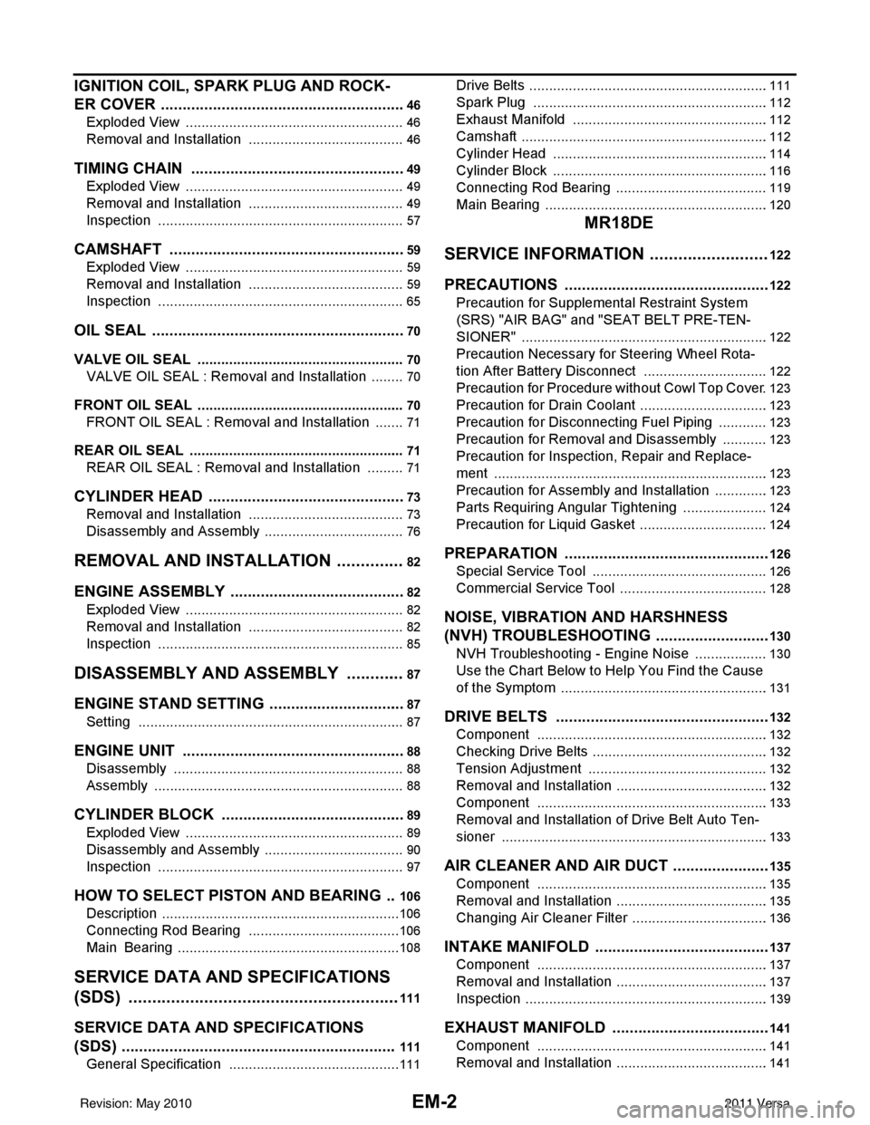
EM-2
IGNITION COIL, SPARK PLUG AND ROCK-
ER COVER .........................................................
46
Exploded View ........................................................46
Removal and Installation ........................................46
TIMING CHAIN ............................................... ...49
Exploded View ..................................................... ...49
Removal and Installation ........................................49
Inspection ...............................................................57
CAMSHAFT .......................................................59
Exploded View ..................................................... ...59
Removal and Installation ........................................59
Inspection ...............................................................65
OIL SEAL ...........................................................70
VALVE OIL SEAL .................................................. ...70
VALVE OIL SEAL : Removal and Installation .........70
FRONT OIL SEAL .................................................. ...70
FRONT OIL SEAL : Removal and Installation ........71
REAR OIL SEAL .................................................... ...71
REAR OIL SEAL : Removal and Installation ..........71
CYLINDER HEAD ........................................... ...73
Removal and Installation ..................................... ...73
Disassembly and Assembly ....................................76
REMOVAL AND INSTALLATION ...............82
ENGINE ASSEMBLY ...................................... ...82
Exploded View ..................................................... ...82
Removal and Installation ........................................82
Inspection ...............................................................85
DISASSEMBLY AND ASSEMBLY .............87
ENGINE STAND SETTING ............................. ...87
Setting ................................................................. ...87
ENGINE UNIT ....................................................88
Disassembly ........................................................ ...88
Assembly ................................................................88
CYLINDER BLOCK ...........................................89
Exploded View ..................................................... ...89
Disassembly and Assembly ....................................90
Inspection ...............................................................97
HOW TO SELECT PISTON AND BEARING ...106
Description ........................................................... ..106
Connecting Rod Bearing .......................................106
Main Bearing .........................................................108
SERVICE DATA AND SPECIFICATIONS
(SDS) ........................................................ ..
111
SERVICE DATA AND SPECIFICATIONS
(SDS) ............................................................... .
111
General Specification .......................................... ..111
Drive Belts ............................................................ .111
Spark Plug ............................................................112
Exhaust Manifold ..................................................112
Camshaft ...............................................................112
Cylinder Head .......................................................114
Cylinder Block .......................................................116
Connecting Rod Bearing .......................................119
Main Bearing .........................................................120
MR18DE
SERVICE INFORMATION .. .......................
122
PRECAUTIONS .............................................. ..122
Precaution for Supplemental Restraint System
(SRS) "AIR BAG" and "SEAT BELT PRE-TEN-
SIONER" .............................................................. .
122
Precaution Necessary for Steering Wheel Rota-
tion After Battery Disconnect ................................
122
Precaution for Procedure without Cowl Top Cover .123
Precaution for Drain Coolant .................................123
Precaution for Disconnecting Fuel Piping ............ .123
Precaution for Removal and Disassembly ............123
Precaution for Inspection, Repair and Replace-
ment ......................................................................
123
Precaution for Assembly and Installation ............. .123
Parts Requiring Angular Tightening ......................124
Precaution for Liquid Gasket .................................124
PREPARATION ................................................126
Special Service Tool ............................................ .126
Commercial Service Tool ......................................128
NOISE, VIBRATION AND HARSHNESS
(NVH) TROUBLESHOOTING ...........................
130
NVH Troubleshooting - Engine Noise .................. .130
Use the Chart Below to Help You Find the Cause
of the Symptom .................................................... .
131
DRIVE BELTS ..................................................132
Component .......................................................... .132
Checking Drive Belts .............................................132
Tension Adjustment ..............................................132
Removal and Installation .......................................132
Component .......................................................... .133
Removal and Installation of Drive Belt Auto Ten-
sioner ....................................................................
133
AIR CLEANER AND AIR DUCT .......................135
Component .......................................................... .135
Removal and Installation .......................................135
Changing Air Cleaner Filter ...................................136
INTAKE MANIFOLD ....................................... ..137
Component .......................................................... .137
Removal and Installation .......................................137
Inspection ............................................................. .139
EXHAUST MANIFOLD .....................................141
Component .......................................................... .141
Removal and Installation .......................................141
Revision: May 2010 2011 Versa
Page 2429 of 3787
OIL PAN (LOWER)EM-39
< ON-VEHICLE REPAIR > [HR16DE]
C
D
E
F
G H
I
J
K L
M A
EM
NP
O
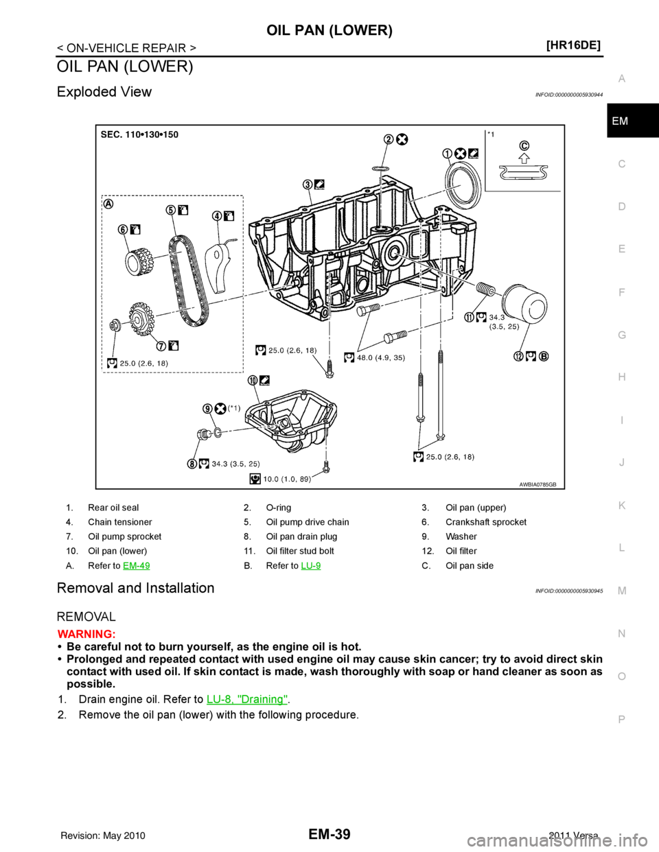
OIL PAN (LOWER)
Exploded ViewINFOID:0000000005930944
Removal and InstallationINFOID:0000000005930945
REMOVAL
WARNING:
• Be careful not to burn yourself, as the engine oil is hot.
• Prolonged and repeated
contact with used engine oil may cau se skin cancer; try to avoid direct skin
contact with used oil. If skin contact is made, w ash thoroughly with soap or hand cleaner as soon as
possible.
1. Drain engine oil. Refer to LU-8, "
Draining".
2. Remove the oil pan (lower) with the following procedure.
1. Rear oil seal 2. O-ring3. Oil pan (upper)
4. Chain tensioner 5. Oil pump drive chain6. Crankshaft sprocket
7. Oil pump sprocket 8. Oil pan drain plug9. Washer
10. Oil pan (lower) 11. Oil filter stud bolt12. Oil filter
A. Refer to EM-49
B. Refer to LU-9C. Oil pan side
AWBIA0785GB
Revision: May 2010 2011 Versa
Page 2432 of 3787
EM-42
< ON-VEHICLE REPAIR >[HR16DE]
OIL PAN (UPPER) AND OIL STRAINER
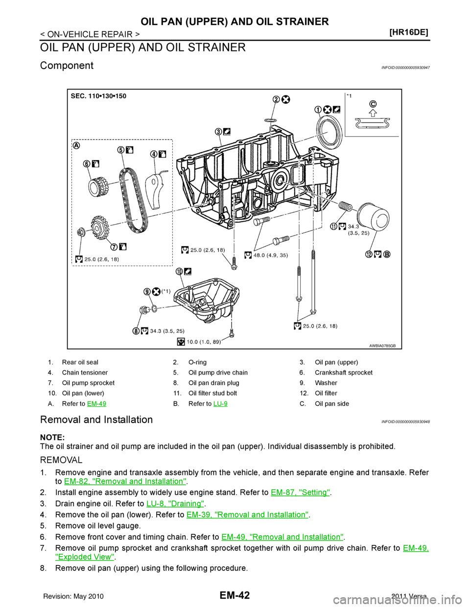
OIL PAN (UPPER) AND OIL STRAINER
ComponentINFOID:0000000005930947
Removal and InstallationINFOID:0000000005930948
NOTE:
The oil strainer and oil pump are included in the oil pan (upper). Individual disassembly is prohibited.
REMOVAL
1. Remove engine and transaxle assembly from the vehicle, and then separate engine and transaxle. Refer
to EM-82, "
Removal and Installation".
2. Install engine assembly to widely use engine stand. Refer to EM-87, "
Setting".
3. Drain engine oil. Refer to LU-8, "
Draining".
4. Remove the oil pan (lower). Refer to EM-39, "
Removal and Installation".
5. Remove oil level gauge.
6. Remove front cover and timing chain. Refer to EM-49, "
Removal and Installation".
7. Remove oil pump sprocket and crankshaft sprocket together with oil pump drive chain. Refer to EM-49,
"Exploded View".
8. Remove oil pan (upper) using the following procedure.
1. Rear oil seal 2. O-ring 3. Oil pan (upper)
4. Chain tensioner 5. Oil pump drive chain 6. Crankshaft sprocket
7. Oil pump sprocket 8. Oil pan drain plug 9. Washer
10. Oil pan (lower) 11. Oil filter stud bolt 12. Oil filter
A. Refer to EM-49
B. Refer to LU-9C. Oil pan side
AWBIA0785GB
Revision: May 2010 2011 Versa