2011 NISSAN LATIO reset
[x] Cancel search: resetPage 3339 of 3787

TROUBLE DIAGNOSISMTC-23
< SERVICE INFORMATION >
C
DE
F
G H
I
K L
M A
B
MTC
N
O P
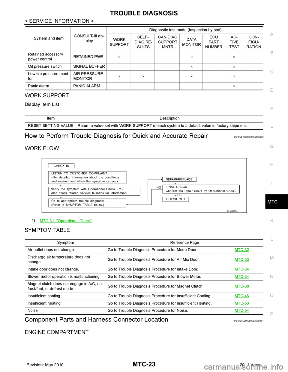
WORK SUPPORT
Display Item List
How to Perform Trouble Diagnosis for Quick and Accurate RepairINFOID:0000000005930843
WORK FLOW
SYMPTOM TABLE
Component Parts and Har ness Connector LocationINFOID:0000000005930844
ENGINE COMPARTMENT
Retained accessory
power controlRETAINED PWR
×× ×
Oil pressure switch SIGNAL BUFFER ××
Low tire pressure moni-
tor AIR PRESSURE
MONITOR
××
× ×
Panic alarm PANIC ALARM ×
System and item
CONSULT-III dis-
play Diagnostic test mode (Inspection by part)
WORK
SUPPORT SELF
−
DIAG RE-
SULTS CAN DIAG
SUPPORT
MNTR DATA
MONITOR ECU
PA R T
NUMBER AC-
TIVE
TEST CON-
FIGU-
RATION
Item Description
RESET SETTING VALUE Return a value set with WORK SUPPORT of each system to a default value in factory shipment.
*1 MTC-31, "Operational Check"
SHA900E
Symptom Reference Page
Air outlet does not change. Go to Trouble Diagnosis Procedure for Mode Door. MTC-32
Discharge air temperature does not
change.Go to Trouble Diagnosis Procedure for Air Mix Door.
MTC-33
Intake door does not change.Go to Trouble Diagnosis Procedure for Intake Door. MTC-34
Blower motor operation is malfunctioning. Go to Trouble Diagnosis Procedure for Blower Motor. MTC-34
Magnet clutch does not engage in A/C, de-
frost/foot, or defrost mode.Go to Trouble Diagnosis Procedure for Magnet Clutch.
MTC-38
Insufficient coolingGo to Trouble Diagnosis Procedure for Insufficient Cooling. MTC-46
Insufficient heatingGo to Trouble Diagnosis Procedure for Insufficient Heating. MTC-53
NoiseGo to Trouble Diagnosis Procedure for Noise. MTC-54
Revision: May 2010 2011 Versa
Page 3586 of 3787

SC-8
< SERVICE INFORMATION >
BATTERY
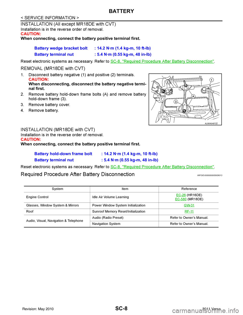
INSTALLATION (All except MR18DE with CVT)
Installation is in the reverse order of removal.
CAUTION:
When connecting, connect the battery positive terminal first.
Reset electronic systems as necessary. Refer to SC-8, "
Required Procedure After Battery Disconnection".
REMOVAL (MR18DE with CVT)
1. Disconnect battery negative (1) and positive (2) terminals.
CAUTION:
When disconnecting, disconnect the battery negative termi-
nal first.
2. Remove battery hold-down frame bolts (A) and remove battery hold-down frame (3).
3. Remove battery cover.
4. Remove battery.
INSTALLATION (MR18DE with CVT)
Installation is in the reverse order of removal.
CAUTION:
When connecting, connect the battery positive terminal first.
Reset electronic systems as necessary. Refer to SC-8, "
Required Procedure After Battery Disconnection".
Required Procedure After Battery DisconnectionINFOID:0000000005929013
Battery wedge bracket bolt : 14.2 N·m (1.4 kg-m, 10 ft-lb)
Battery terminal nut : 5.4 N·m (0.55 kg-m, 48 in-lb)
ALMIA0487ZZ
Battery hold-down frame bolt : 14.2 N·m (1.4 kg-m, 10 ft-lb)
Battery terminal nut : 5.4 N·m (0.55 kg-m, 48 in-lb)
System ItemReference
Engine Control Idle Air Volume Learning EC-26
(HR16DE)
EC-580
(MR18DE)
Glasses, Window System & Mirrors Power Window System Initialization GW-31
RoofSunroof Memory Reset/Initialization RF-11
Audio, Visual, Navigation & TelephoneAudio (Radio Preset)
Refer to Owner’s Manual.
Navigation System Refer to Owner’s Manual.
Revision: May 2010 2011 Versa
Page 3652 of 3787

SRS-18
< SYMPTOM DIAGNOSIS >
TROUBLE DIAGNOSIS
HOW TO CHANGE BETWEEN SELF-DIAGNOSIS MODE AND USER MODE WITH CONSULT-III
From User Mode to Diagnosis Mode
After selecting “AIR BAG” on the “SELECT SYSTEM” screen, User mode automatically changes to Diagnosis
mode.
From Diagnosis Mode to User Mode
To return to User mode from Diagnosis mode, touch “BACK” key of CONSULT-III until “SELECT SYSTEM”
appears, Diagnosis mode automatically changes to User mode.
HOW TO ERASE SELF-DIAGNOSIS RESULTS
NOTE:
If the memory in “SELF-DIAG [PAST]” is not erased, User mode will continue to show the system mal-
function by the operation of th e warning lamp even if the malfun ction is repaired completely.
• “SELF-DIAG [CURRENT]” A current self-diagnosis result is displayed on the CO NSULT-III screen in real time. After the malfunction is
repaired completely, no malfunction is detected on “SELF-DIAG [CURRENT]”.
• “SELF-DIAG [PAST]” Return to the “SELF-DIAG [CURRENT]” CONSULT-III screen by touching “BACK” key of CONSULT-III and
select “SELF-DIAG [CURRENT]” in SELECT DIAG MODE. Touch “ERASE” in “SELF-DIAG [CURRENT]”
mode.
• “TROUBLE DIAG RECORD”
The memory of “TROUBLE DI AG RECORD” cannot be erased.
Self-Diagnosis Function (Without CONSULT-III)INFOID:0000000006211121
The reading of these results is accomplished using one of two modes — “User mode” and “Diagnosis mode”.
HOW TO CHANGE BETWEEN USER MODE AND SELF-DIAGNOSIS MODE WITHOUT CONSULT-
AIR BAG diagnostic mode Description
SELF-DIAG [CURRENT] A current Self-diagnosis result is displayed on the CO
NSULT-III screen in real time. This refers to a mal-
functioning part requiring replacement.
SELF-DIAG [PAST] Diagnosis results previously stored in the memory are displayed on the CONSULT-III screen. The
stored results will remain until the memory is erased.
TROUBLE DIAG RECORD With TROUBLE DIAG RECORD, diagnosis results previously erased by a reset operation can be dis-
played on the CONSULT-III screen.
ECU DISCRIMINATED NO. Air bag diagnosis sensor unit ECU discriminated number (identification number) is displayed. Air bag
diagnosis sensor unit has individual ECU discriminated number (identification number) based on model
and equipment.
PASSENGER AIR BAG The STATUS (readiness) of the front passenger air bag module is displayed. The STATUS displayed
(ON/OFF) depends on the signals supplied to the occupant classification system control module and
air bag diagnosis sensor unit. Refer to
SRS-6, "
Occupant Classification System (OCS)" for more in-
formation.
Revision: May 2010 2011 Versa
Page 3659 of 3787

TROUBLE DIAGNOSISSRS-25
< SYMPTOM DIAGNOSIS >
C
DE
F
G
I
J
K L
M A
B
SRS
N
O P
2. Touch “TROUBLE DIAG RECORD”. NOTE:
With “TROUBLE DIAG RECORD”, di agnosis results previously erased by a reset operation can be
displayed.
3. Diagnostic code is displayed on “TROUBLE DIAG RECORD”.
4. Touch “PRINT”.
5. Compare diagnostic codes to "CONSULT-III Diagnos tic Code Chart ("SELF-DIAG [PAST]" or "TROUBLE
DIAG RECORD")".
6. Touch “BACK” key of CONSULT- III until “SELECT SYSTEM” appears.
7. Turn ignition switch OFF, then turn off and disconnect CONSULT-III, and both battery cables.
8. Repair the system as outlined by the “Repair orde r” in “Intermittent Malfunction Diagnostic Code Chart”,
that corresponds to the self-diagnostic result. For r eplacement procedure of component parts, refer to the
Removal and Installation procedure for the appropriate component.
9. Go to "DIAGNOSTIC PROCEDURE 3", for final checking.
CONSULT-III Diagnostic Code Chart ("SELF-DI AG [PAST]" or "TROUBLE DIAG RECORD")
Diagnostic item Explanation Repair order
Recheck SRS at each replacement
NO DTC IS DETECTED When malfunction is
indicated by the “AIR
BAG” warning lamp in
User mode.
• Low battery voltage (L
ess than 9V) • Go to "DIAGNOSTIC PROCEDURE
3" .
• Self-diagnostic result “SELF-DIAG [PAST]” (previously stored in the
memory) might not be erased after
repair.
• Intermittent malfunction has been detected in the past. • Go to "DIAGNOSTIC PROCEDURE
4" .
• Go to "DIAGNOSTIC PROCEDURE
5" .
• No malfunction is detected. —
DRIVER AIRBAG MODULE [OPEN]
[B1049] or [B1054] Driver air bag module circuit is open (including the spiral ca-
ble).
1. Visually check the wiring harness
connection.
2. Replace the harness if it has visi- ble damage.
3. Replace driver air bag module.
4. Replace the spiral cable.
5. Replace the air bag diagnosis sensor unit.
6. Replace the related harness.
DRIVER AIRBAG MODULE
[VB-SHORT]
[B1050] or [B1055] Driver air bag module circuit is shorted to some power supply
circuit (including the spiral cable).
DRIVER AIRBAG MODULE [GND-SHORT]
[B1051] or [B1056] Driver air bag module circuit is shorted to ground (including
the spiral cable).
DRIVER AIRBAG MODULE [SHORT]
[B1052] or [B1057] Driver air bag module circuits are shorted to each other.
ASSIST A/B MODULE [OPEN]
[B1065] or [B1070] Front passenger air bag module circuit is open.
1. Visually check the wiring harness
connection.
2. Replace the harness if it has visi-
ble damage.
3. Replace front passenger air bag module.
4. Replace the air bag diagnosis sensor unit.
5. Replace the related harness.
ASSIST A/B MODULE
[VB-SHORT]
[B1066] or [B1071] Front passenger air bag module circuit is shorted to some
power supply circuit.
ASSIST A/B MODULE [GND-SHORT]
[B1067] or [B1072] Front passenger air bag module circuit is shorted to ground.
ASSIST A/B MODULE [SHORT]
[B1068] or [B1073] Front passenger air bag module circuits are shorted to each
other.
Revision: May 2010
2011 Versa