Page 213 of 3787

AT-196
< SERVICE INFORMATION >
TROUBLE DIAGNOSIS FOR SYMPTOMS
OK >>INSPECTION END
NG >> GO TO 3.
3.CHECK TCM
1. Check TCM input/output signals. Refer to AT-75, "
TCM Terminal and Reference Value" .
2. If NG, recheck TCM pin terminals for damage or loose connection with harness connector.
OK or NG
OK >> INSPECTION END
NG >> Repair or replace damaged parts.
Engine Speed Does Not Return to Idle (Light Braking D4→ D3)INFOID:0000000005928261
SYMPTOM:
Engine speed does not smoothly return to idle when A/T shifts from D4 to D3 on “Cruise Test — Part
1”.
DIAGNOSTIC PROCEDURE
1.CHECK SELF-DIAGNOSTIC RESULTS
Perform self-diagnosis. Refer to AT-77, "
CONSULT-III Function (TRANSMISSION)" or AT-82, "Diagnosis Pro-
cedure without CONSULT-III" .
Is any malfunction detected by self-diagnostic results?
YES >> Check the malfunctioning system. Refer to AT-77, "CONSULT-III Function (TRANSMISSION)" or
AT-82, "
Diagnosis Procedure without CONSULT-III" .
NO >> GO TO 2.
2.CHECK ACCELERATOR PEDAL POSITION SENSOR
Check accelerator pedal position sensor. Refer to EC-415, "
Description" (HR16DE), EC-982, "Component
Description" (MR18DE).
OK or NG
OK >> GO TO 3.
NG >> Repair or replace accelerator pedal position sensor.
3.CHECK A/T FLUID CONDITION
1. Remove oil pan. Refer to AT-237, "
Component" .
2. Check A/T fluid condition. Refer to AT-51, "
Inspections Before Trouble Diagnosis" .
OK or NG
OK >> GO TO 5.
NG >> GO TO 4.
4.DETECT MALFUNCTIONING ITEM
1. Remove control valve assembly. Refer to AT-222, "
Control Valve Assembly and Accumulators" .
2. Check the following items:
- Overrun clutch control valve
- Overrun clutch reducing valve
- Overrun clutch solenoid valve
3. Disassemble A/T. Refer to AT-257, "
Disassembly" .
4. Check the following items:
- Overrun clutch assembly. Refer to AT-307, "
Forward and Overrun Clutches" .
OK or NG
OK >> GO TO 6.
NG >> Repair or replace damaged parts.
5.DETECT MALFUNCTIONING ITEM
1. Remove control valve assembly. Refer to AT-222, "
Control Valve Assembly and Accumulators" .
2. Check the following items:
- Overrun clutch control valve
- Overrun clutch reducing valve
- Overrun clutch solenoid valve
Revision: May 2010 2011 Versa
Page 232 of 3787
SHIFT CONTROL SYSTEMAT-215
< SERVICE INFORMATION >
DE
F
G H
I
J
K L
M A
B
AT
N
O P
7. Remove the plate (1) from the A/T shift selector assembly. : Vehicle front
8. Remove the lock plate (1) from the shift selector control cable (2).
: Vehicle front
9. Remove the shift selector control cable (2) from the A/T shift selector assembly.
10. Insert suitable tool at points (A) and (B) as shown, and press both tabs (E) and (F) at the front (C) and rear (D) slightly toward
the center of the A/T shift select or assembly to remove the A/T
shift selector assembly from the underside of the vehicle.
: Vehicle front
INSTALLATION
Installation is in the reverse order of removal.
SCIA6967E
SCIA6968E
SCIA6970E
Revision: May 2010 2011 Versa
Page 233 of 3787
AT-216
< SERVICE INFORMATION >
SHIFT CONTROL SYSTEM
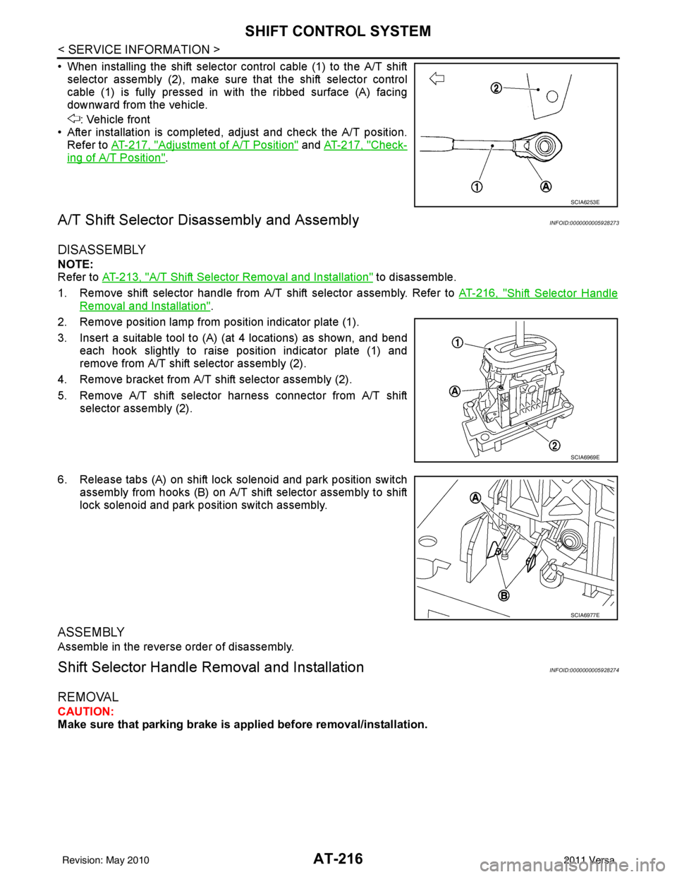
• When installing the shift selector control cable (1) to the A/T shiftselector assembly (2), make sure that the shift selector control
cable (1) is fully pressed in with the ribbed surface (A) facing
downward from the vehicle.
: Vehicle front
• After installation is completed, adjust and check the A/T position. Refer to AT-217, "
Adjustment of A/T Position" and AT-217, "Check-
ing of A/T Position".
A/T Shift Selector Di sassembly and AssemblyINFOID:0000000005928273
DISASSEMBLY
NOTE:
Refer to AT-213, "
A/T Shift Selector Removal and Installation" to disassemble.
1. Remove shift selector handle from A/T shift selector assembly. Refer to AT-216, "
Shift Selector Handle
Removal and Installation".
2. Remove position lamp from position indicator plate (1).
3. Insert a suitable tool to (A) (at 4 locations) as shown, and bend each hook slightly to raise position indicator plate (1) and
remove from A/T shift selector assembly (2).
4. Remove bracket from A/T shift selector assembly (2).
5. Remove A/T shift selector harness connector from A/T shift selector assembly (2).
6. Release tabs (A) on shift lock solenoid and park position switch assembly from hooks (B) on A/T shift selector assembly to shift
lock solenoid and park position switch assembly.
ASSEMBLY
Assemble in the reverse order of disassembly.
Shift Selector Handle Removal and InstallationINFOID:0000000005928274
REMOVAL
CAUTION:
Make sure that parking brake is applied before removal/installation.
SCIA6253E
SCIA6969E
SCIA6977E
Revision: May 2010 2011 Versa
Page 279 of 3787
AT-262
< SERVICE INFORMATION >
DISASSEMBLY
• HR16DE engine models
• MR18DE engine models
b. Remove bracket from converter housing
c. Remove converter housing by tapping it lightly.
d. Remove O-ring from differential lubricant hole.
24. Remove final drive assembly from transaxle case.
SCIA6211J
SCIA7970E
SCIA3281E
SAT228F
Revision: May 2010 2011 Versa
Page 288 of 3787
DISASSEMBLYAT-271
< SERVICE INFORMATION >
DE
F
G H
I
J
K L
M A
B
AT
N
O P
i. Remove side cover bolts (1), then remove side cover by lightly tapping it with a soft hammer.
CAUTION:
Be careful not to damage cover.
ii. Remove side cover gasket from side cover.
iii. Set manual shaft in "P" position to lock idler gear and output gear.
iv. Unlock both idler gear and output gear lock nuts with a suitable tool.
v. Remove idler gear and output gear lock nuts.
vi. Remove out put gear (1) and idler gear (2) using Tool (A).
vii. Removing reduction pinion gear and output shaft from transaxle case.
viii. Remove reduction pinion gear adjusting shim (1) from reduction pinion gear (2).
ix. Remove output gear adjusting spacer (3) from output shaft (4).
b. MR18DE engine models.
SCIA6039J
SAT704D
Tool number : ST27180001 (J-25726-A)
SCIA6991E
SCIA5902J
Revision: May 2010 2011 Versa
Page 289 of 3787
AT-272
< SERVICE INFORMATION >
DISASSEMBLY
i. Remove side cover bolts (A) and (B).CAUTION:
• Do not mix bolts (A) and (B).
• Always replace bolts (A) as they are self-sealing bolts.
ii. Remove side cover by lightly tapping it using a soft hammer. CAUTION:
• Be careful not to drop output shaft assembly. It might
come out when removing side cover.
• Be careful not to damage side cover.
iii. Remove output shaft adjusting shim.
iv. Remove output shaft assembly.
• If output shaft assembly came off with side cover, tap side-cover with a soft hammer to separate.
CAUTION:
Be careful not to damage side cover.
SCIA7939E
SAT434D
SAT440D
SAT035F
SAT435D
Revision: May 2010 2011 Versa
Page 305 of 3787
AT-288
< SERVICE INFORMATION >
REPAIR FOR COMPONENT PARTS
f. Install check balls (1), line pressure relief valve springs (2) andtorque converter pressure holding spring (3) in their proper posi-
tions in control valve lower body (4).
g. Install bolts (E) from bottom of control valve lower body (1). Using bolts (E) as guides, install separating plate (2) as a set.
h. Install support plates (3) on control valve lower body (1).
i. Install control valve lower body (1) on control valve inter body (2) using reamer bolts (F) as guides, and tighten reamer bolts (F)
slightly.
2. Install O-rings on solenoid valves and terminal body.
SCIA6491J
SCIA7013E
SCIA7014E
SCIA7180E
Revision: May 2010 2011 Versa
Page 310 of 3787
REPAIR FOR COMPONENT PARTSAT-293
< SERVICE INFORMATION >
DE
F
G H
I
J
K L
M A
B
AT
N
O P
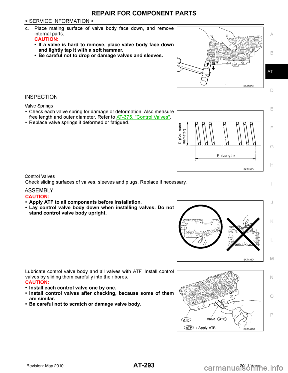
c. Place mating surface of valve body face down, and remove internal parts.
CAUTION:
• If a valve is hard to remove, place valve body face downand lightly tap it with a soft hammer.
• Be careful not to drop or damage valves and sleeves.
INSPECTION
Va l v e Sp r i n g s
• Check each valve spring for damage or deformation. Also measure
free length and outer diameter. Refer to AT-375, "
Control Valves".
• Replace valve springs if deformed or fatigued.
Control Valves
Check sliding surfaces of valves, sleeves and plugs. Replace if necessary.
ASSEMBLY
CAUTION:
• Apply ATF to all componen ts before installation.
• Lay control valve body down wh en installing valves. Do not
stand control valve body upright.
Lubricate control valve body and all valves with ATF. Install control
valves by sliding them carefully into their bores.
CAUTION:
• Install each control valve one by one.
• Install control valves after checking, because some of them are similar.
• Be careful not to scratch or damage valve body.
SAT137D
SAT138D
SAT139D
SAT140DA
Revision: May 2010 2011 Versa


