2011 NISSAN LATIO checking oil
[x] Cancel search: checking oilPage 217 of 3787

AT-200
< SERVICE INFORMATION >
TROUBLE DIAGNOSIS FOR SYMPTOMS
OK >> GO TO 3
NG >> Check transmission range switch. Refer to AT-175, "
Component Inspection" .
2.CHECK TRANSMISSION RANGE SWITCH CIRCUIT
Without CONSULT-III
1. Turn ignition switch ON. (Do not start engine.)
2. Check voltage between TCM connector terminals and ground
while moving selector lever through each position. Refer to AT-
91, "Wiring Diagram - AT - TR/SW" .
B: Battery voltage
0: 0V
OK or NG
OK >> GO TO 3
NG >> Check transmission range switch. Refer to AT-175, "
Component Inspection" .
3.CHECK A/T POSITION
Check A/T position. Refer to AT-217, "
Checking of A/T Position" .
OK or NG
OK >> GO TO 4.
NG >> Adjust A/T position. Refer to AT-217, "
Adjustment of A/T Position" .
4.CHECK OUTPUT SPEED SENSOR AND VEHICLE SPEED SIGNAL CIRCUIT
Check output speed sensor and vehicle speed signal circuit. Refer to AT-100
and/or AT-153 .
OK or NG
OK >> GO TO 5.
NG >> Repair or replace output speed sens or and/or vehicle speed signal circuits.
5.CHECK A/T FLUID CONDITION
1. Remove oil pan. Refer to AT-237, "
Component" .
2. Check A/T fluid condition. Refer to AT-51, "
Inspections Before Trouble Diagnosis" .
OK or NG
OK >> GO TO 7.
NG >> GO TO 6.
6.DETECT MALFUNCTIONING ITEM
1. Remove control valve assembly. Refer to AT-222, "
Control Valve Assembly and Accumulators" .
2. Check the following items:
- Shift valve A
- Shift solenoid valve A
Selector lever position Te r m i n a l
36 35 34 27 26
“P”, “N” B0000 “R” 0B000
“D” 0 0 B 0 0
“2” 000B0
“1” 0000B
SCIA7162E
Revision: May 2010 2011 Versa
Page 220 of 3787

TROUBLE DIAGNOSIS FOR SYMPTOMSAT-203
< SERVICE INFORMATION >
DE
F
G H
I
J
K L
M A
B
AT
N
O P
2. Check voltage between TCM connector terminals and ground while moving selector lever through each position. Refer to AT-
91, "Wiring Diagram - AT - TR/SW" .
B: Battery voltage
0: 0V
OK or NG
OK >> GO TO 5
NG >> Check transmission range switch. Refer to AT-175, "
Component Inspection" .
5.CHECK A/T POSITION
Check A/T position. Refer to AT-217, "
Checking of A/T Position" .
OK or NG
OK >> GO TO 6.
NG >> Adjust A/T position. Refer to AT-217, "
Adjustment of A/T Position" .
6.CHECK OUTPUT SPEED SENSOR AND VEHICLE SPEED SIGNAL CIRCUIT
Check output speed sensor and vehicle speed signal circuit. Refer to AT-100
and/or AT- 1 5 3 .
OK or NG
OK >> GO TO 7.
NG >> Repair or replace output speed sensor and/or vehicle speed signal circuits.
7.CHECK ACCELERATOR PEDAL POSITION SENSOR
Check accelerator pedal position sensor. Refer to EC-415, "
Description" (HR16DE), EC-982, "Component
Description" (MR18DE).
OK or NG
OK >> GO TO 8.
NG >> Repair or replace accelerator pedal position sensor.
8.CHECK A/T FLUID CONDITION
1. Remove oil pan. Refer to AT-237, "
Component" .
2. Check A/T fluid condition. Refer to AT-51, "
Inspections Before Trouble Diagnosis" .
OK or NG
OK >> GO TO 10.
NG >> GO TO 9.
9.DETECT MALFUNCTIONING ITEM
1. Remove control valve assembly. Refer to AT-222, "
Control Valve Assembly and Accumulators" .
2. Check the following.
- Shift valve A
Selector lever position Te r m i n a l
36 35 34 27 26
“P”, “N” B 0 0 0 0
“R” 0B000
“D” 0 0 B 0 0
“2” 0 0 0 B 0
“1” 0 0 0 0 B
SCIA7162E
Revision: May 2010 2011 Versa
Page 242 of 3787
ON-VEHICLE SERVICEAT-225
< SERVICE INFORMATION >
DE
F
G H
I
J
K L
M A
B
AT
N
O P
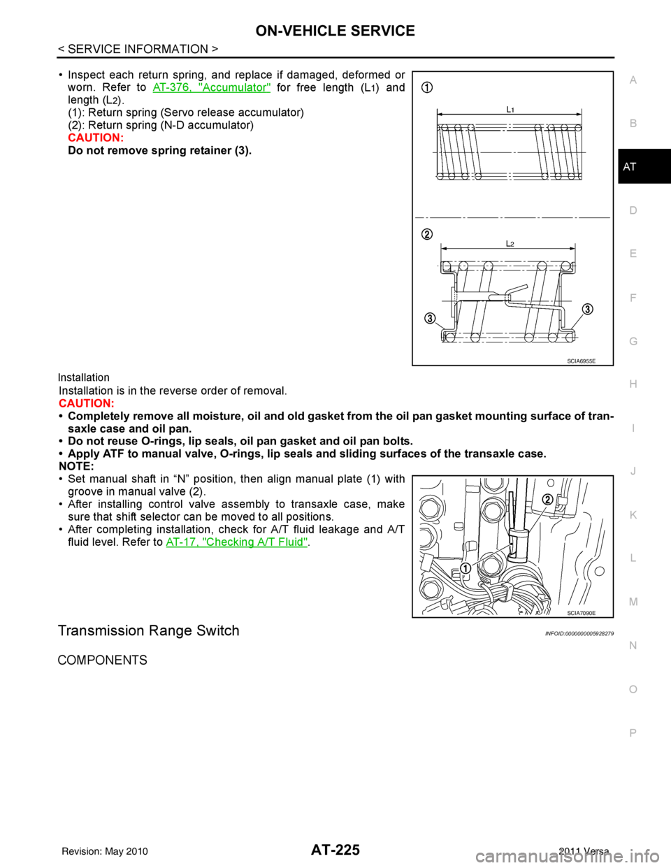
• Inspect each return spring, and replace if damaged, deformed or worn. Refer to AT-376, "
Accumulator" for free length (L1) and
length (L
2).
(1): Return spring (Servo release accumulator)
(2): Return spring (N-D accumulator)
CAUTION:
Do not remove spring retainer (3).
Installation
Installation is in the reverse order of removal.
CAUTION:
• Completely remove all moisture, oil and old gasket from the oil pan gasket mounting surface of tran-
saxle case and oil pan.
• Do not reuse O-rings, lip seals, oil pan gasket and oil pan bolts.
• Apply ATF to manual valve, O-rings, lip seals and sliding surfaces of the transaxle case.
NOTE:
• Set manual shaft in “N” position, then align manual plate (1) with groove in manual valve (2).
• After installing control valve assembly to transaxle case, make sure that shift selector can be moved to all positions.
• After completing installation, check for A/T fluid leakage and A/T fluid level. Refer to AT-17, "
Checking A/T Fluid".
Transmission Range SwitchINFOID:0000000005928279
COMPONENTS
SCIA6955E
SCIA7090E
Revision: May 2010 2011 Versa
Page 248 of 3787

ON-VEHICLE SERVICEAT-231
< SERVICE INFORMATION >
DE
F
G H
I
J
K L
M A
B
AT
N
O P
• After installing differential side oil seal, check A/T fluid leakage and A/T fluid level. Refer to AT-17, "Checking
A/T Fluid".
Revision: May 2010 2011 Versa
Page 1014 of 3787

CO-14
< ON-VEHICLE MAINTENANCE >[HR16DE]
RADIATOR
RADIATOR
Checking Radiator CapINFOID:0000000005930779
• Check valve seat of radiator cap.
- Check if valve seat is swollen to the extent that the edge of the
plunger cannot be seen when watching it vertically from the top.
- Check if valve seat has no soil and damage.
• Pull negative-pressure valve to open it, and make sure that it is completely closed when released.
- Make sure that there is no dirt or damage on the valve seat of radi-
ator cap negative-pressure valve.
- Make sure that the valve operates properly in the opening and closing conditions.
• Check radiator cap relief pressure using suitable tool and Tool.
- When connecting the radiator cap to the tester, apply water or coolant to the cap seal surface.
- Replace the radiator cap if ther e is an abnormality in the negative-
pressure valve, or if the open-valve pr essure is outside of the standard values.
• Replace radiator cap if there it does not comply to specifications to the above three checks.
CAUTION:
When installing radiator cap, thoroughly wipe out the radiator filler neck to remove any waxy residue
or foreign material.
Checking RadiatorINFOID:0000000005930780
Check radiator for mud or clogging. If necessary, clean radiator as follows.
• Be careful not to bend or damage radiator fins.
• When radiator is cleaned without removal, remove all surrounding parts such as cooling fan, radiator shroud and horns. Then tape harness and connectors to prevent water from entering.
1. Apply water by hose to the back side of the radiator core vertically downward.
2. Apply water again to all radiator core surface once per minute.
3. Stop washing if any stains no longer flow out from radiator.
4. Blow air into the back side of radiator core vertically downward.
PBIC2816E
SMA967B
Tool number : EG17650301 (J-33984-A)
Standard: 78 – 98 kPa (0.78 - 0.98 bar, 0.8 – 1.0 kg/cm
2, 11
– 14 psi)
Limit: 59 kPa (0.59 bar, 0.6 kg/cm
2, 9 psi)
WBIA0570E
Revision: May 2010 2011 Versa
Page 1023 of 3787

THERMOSTATCO-23
< ON-VEHICLE REPAIR > [HR16DE]
C
D
E
F
G H
I
J
K L
M A
CO
NP
O
• Install thermostat (2) into the cylinder block (1) with jiggle valve (A)
facing upwards.
Water Inlet.
After installation, fix water inlet clip (A) on the oil level gauge guide
(1) positioned (B) as shown.
InspectionINFOID:0000000005930792
INSPECTION AFTER REMOVAL
WARNING:
Use a protector to prevent a burn during the work.
Thermostat
• Place a thread (A) so that it is caught in the valves of thermostat(1). Immerse fully in a container (B) filled with water. Heat while
stirring.
• The valve opening temperature is the temperature at which the valve opens and falls from the thread.
• Continue heating. Check the full-open valve lift amount.
• After checking the full-open valve lift amount, lower the water tem- perature and check the valve closing temperature.
• If out of the standard, replace thermostat.
INSPECTION AFTER INSTALLATION
• Check that the reservoir tank cap is tightened.
• Check for leaks of engine coolant using suitable tools. Refer to CO-11, "
Inspection".
• Start and warm up the engine. Visually make sure that there is no leaks of engine coolant.
PBIC3812E
PBIC3755E
Standard : Refer to CO-26, "Thermostat".
PBIC3314J
Revision: May 2010 2011 Versa
Page 1039 of 3787

RADIATORCO-39
< SERVICE INFORMATION > [MR18DE]
C
D
E
F
G H
I
J
K L
M A
CO
NP
O
RADIATOR
Checking Radiator CapINFOID:0000000005930808
• Check valve seat of radiator cap.
- Check if valve seat is swollen to the extent that the edge of the
plunger cannot be seen when watching it vertically from the top.
- Check if valve seat has no soil and damage.
• Pull negative-pressure valve to open it, and make sure that it is completely closed when released.
- Make sure that there is no dirt or damage on the valve seat of radi-
ator cap negative-pressure valve.
- Make sure that the valve operates properly in the opening and closing conditions.
• Check radiator cap relief pressure using suitable tool and Tool.
- When connecting the radiator cap to the tester, apply water or coolant to the cap seal surface.
- Replace the radiator cap if there is an abnormality in the negative- pressure valve, or if the open-valve pressure is outside of the standard values.
• Replace radiator cap if there it does not comply to specifications to the above three checks.
CAUTION:
When installing radiator cap, thor oughly wipe out the radiator filler neck to remove any waxy residue
or foreign material.
Checking RadiatorINFOID:0000000005930809
Check radiator for mud or clogging. If necessary, clean radiator as follows.
• Be careful not to bend or damage radiator fins.
• When radiator is cleaned without removal, remove all surrounding parts such as cooling fan, radiator shroud and horns. Then tape harness and connectors to prevent water from entering.
1. Apply water by hose to the back side of the radiator core vertically downward.
2. Apply water again to all radiator core surface once per minute.
3. Stop washing if any stains no longer flow out from radiator.
4. Blow air into the back side of radiator core vertically downward.
PBIC2816E
SMA967B
Tool number : EG17650301 (J-33984-A)
Standard: 78 – 98 kPa (0.78 - 0.98 bar, 0.8 – 1.0 kg/cm
2, 11
– 14 psi)
Limit: 59 kPa (0.59 bar, 0.6 kg/cm
2, 9 psi)
WBIA0570E
Revision: May 2010 2011 Versa
Page 1059 of 3787
CVT-4
CONSULT-III Reference Value in Data Monitor
Mode .................................................................... ..
135
Wiring Diagram - CVT - ODSW .............................136
Diagnosis Procedure .............................................136
Component Inspection ...........................................138
SHIFT POSITION INDICATOR CIRCUIT ........140
Description ........................................................... ..140
CONSULT-III Reference Value in Data Monitor
Mode .................................................................... ..
140
Diagnosis Procedure .............................................140
TROUBLE DIAGNOSIS FOR SYMPTOMS .....141
Wiring Diagram - CVT - NONDTC ....................... ..141
O/D OFF Indicator Lamp Does Not Come On .......143
Engine Cannot Be Started in "P" and "N" Position ..145
In "P" Position, Vehicle Moves Forward or Back-
ward When Pushed ...............................................
145
In "N" Position, Vehicle Moves ............................ ..146
Large Shock "N" → "R" Position .......................... ..146
Vehicle Does Not Creep Backward in "R" Position ..147
Vehicle Does Not Creep Forward in "D" or "L" Po-
sition ......................................................................
148
Vehicle Speed Does Not Change in "L" Position ...149
Vehicle Speed Does Not Change in overdrive-off
mode ......................................................................
150
Vehicle Speed Does Not Change in "D" Position ..151
Vehicle Does Not Decelerate by Engine Brake .....151
CVT SHIFT LOCK SYSTEM ........................... .153
Description ........................................................... ..153
Shift Lock System Electrical Parts Location ..........154
Wiring Diagram - CVT - SHIFT ..............................155
Diagnosis Procedure .............................................155
TCM ..................................................................159
Removal and Installation ..................................... ..159
SHIFT CONTROL SYSTEM ............................160
Removal and Installation ..................................... ..160
CVT Shift Selector Disassembly and Assembly ....163
Shift Selector Handle Removal and Installation ....163
Adjustment of CVT Position ................................. ..164
Checking of CVT Position ......................................164
KEY INTERLOCK CABLE ...............................166
Removal and Installation ..................................... ..166
PRIMARY SPEED SENSOR ...........................169
Exploded View ..................................................... ..169
Removal and Installation .......................................169
Inspection ............................................................. .169
SECONDARY SPEED SENSOR ......................170
Exploded View ..................................................... .170
Removal and Installation .......................................170
Inspection ............................................................. .170
AIR BREATHER HOSE ....................................171
Removal and Installation .......................................171
OIL PAN .......................................................... ..172
Exploded View ..................................................... .172
Removal and Installation .......................................172
Inspection ............................................................. .173
DIFFERENTIAL SIDE OIL SEAL .....................174
Removal and Installation .......................................174
CVT OIL WARMER SYSTEM ......................... ..175
WATER HOSE ........................................................ .175
WATER HOSE : Exploded View ...........................175
WATER HOSE : Removal and Installation ...........175
WATER HOSE : Inspection ..................................176
CVT FLUID COOLER HOSE .................................. .176
CVT FLUID COOLER HOSE : Exploded View .....177
CVT FLUID COOLER HOSE : Removal and In-
stallation ................................................................
177
CVT FLUID COOLER HOSE : Inspection .............179
CVT OIL WARMER ................................................ .179
CVT OIL WARMER : Exploded View ....................179
CVT OIL WARMER : Removal and Installation ....179
CVT OIL WARMER : Inspection .......................... .179
TRANSAXLE ASSEMBLY ...............................180
Removal and Installation .......................................180
SERVICE DATA AND SPECIFICATIONS
(SDS) .............................................................. ..
183
General Specification ........................................... .183
Vehicle Speed When Shifting Gears .....................183
Stall Speed ............................................................183
Line Pressure ........................................................183
Solenoid Valves ....................................................184
CVT Fluid Temperature Sensor ............................184
Primary Speed Sensor ..........................................184
Secondary Speed Sensor .................................... .184
Removal and Installation .......................................184
Revision: May 2010 2011 Versa