2011 NISSAN LATIO EGR TEMP Sensor
[x] Cancel search: EGR TEMP SensorPage 1778 of 3787
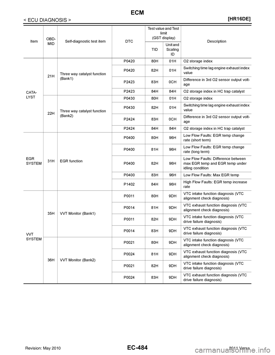
EC-484
< ECU DIAGNOSIS >[HR16DE]
ECM
CATA-
LYST21H
Three way catalyst function
(Bank1) P0420 80H 01H O2 storage index
P0420 82H 01H
Switching time lag engine exhaust index
value
P2423 83H 0CH Difference in 3rd O2 sensor output volt-
age
P2423 84H 84H O2 storage index in HC trap catalyst
22H Three way catalyst function
(Bank2) P0430 80H 01H O2 storage index
P0430 82H 01H
Switching time lag engine exhaust index
value
P2424 83H 0CH Difference in 3rd O2 sensor output volt-
age
P2424 84H 84H O2 storage index in HC trap catalyst
EGR
SYSTEM 31H EGR function P0400 80H 96H
Low Flow Faults: EGR temp change
rate (short term)
P0400 81H 96H Low Flow Faults: EGR temp change
rate (long term)
P0400 82H 96H Low Flow Faults: Difference between
max EGR temp and EGR temp under
idling condition
P0400 83H 96H Low Flow Faults: Max EGR temp
P1402 84H 96H High Flow Faults: EGR temp increase
rate
VVT
SYSTEM 35H VVT Monitor (Bank1)
P0011 80H 9DH
VTC intake function diagnosis (VTC
alignment check diagnosis)
P0014 81H 9DH VTC exhaust function diagnosis (VTC
alignment check diagnosis)
P0011 82H 9DH VTC intake function diagnosis (VTC
drive failure diagnosis)
P0014 83H 9DH VTC exhaust function diagnosis (VTC
drive failure diagnosis)
36H VVT Monitor (Bank2) P0021 80H 9DH
VTC intake function diagnosis (VTC
alignment check diagnosis)
P0024 81H 9DH VTC exhaust function diagnosis (VTC
alignment check diagnosis)
P0021 82H 9DH VTC intake function diagnosis (VTC
drive failure diagnosis)
P0024 83H 9DH VTC exhaust function diagnosis (VTC
drive failure diagnosis)
Item
OBD-
MID Self-diagnostic test item
DTCTest value and Test
limit
(GST display) Description
TID Unit and
Scaling ID
Revision: May 2010 2011 Versa
Page 1852 of 3787
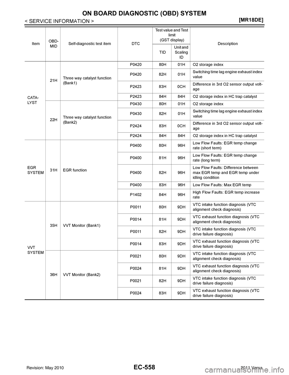
EC-558
< SERVICE INFORMATION >[MR18DE]
ON BOARD DIAGNOSTIC (OBD) SYSTEM
CATA-
LYST21H
Three way catalyst function
(Bank1) P0420 80H 01H O2 storage index
P0420 82H 01H
Switching time lag engine exhaust index
value
P2423 83H 0CH Difference in 3rd O2 sensor output volt-
age
P2423 84H 84H O2 storage index in HC trap catalyst
22H Three way catalyst function
(Bank2) P0430 80H 01H O2 storage index
P0430 82H 01H
Switching time lag engine exhaust index
value
P2424 83H 0CH Difference in 3rd O2 sensor output volt-
age
P2424 84H 84H O2 storage index in HC trap catalyst
EGR
SYSTEM 31H EGR function P0400 80H 96H
Low Flow Faults: EGR temp change
rate (short term)
P0400 81H 96H Low Flow Faults: EGR temp change
rate (long term)
P0400 82H 96H Low Flow Faults: Difference between
max EGR temp and EGR temp under
idling condition
P0400 83H 96H Low Flow Faults: Max EGR temp
P1402 84H 96H High Flow Faults: EGR temp increase
rate
VVT
SYSTEM 35H VVT Monitor (Bank1)
P0011 80H 9DH
VTC intake function diagnosis (VTC
alignment check diagnosis)
P0014 81H 9DH VTC exhaust function diagnosis (VTC
alignment check diagnosis)
P0011 82H 9DH VTC intake function diagnosis (VTC
drive failure diagnosis)
P0014 83H 9DH VTC exhaust function diagnosis (VTC
drive failure diagnosis)
36H VVT Monitor (Bank2) P0021 80H 9DH
VTC intake function diagnosis (VTC
alignment check diagnosis)
P0024 81H 9DH VTC exhaust function diagnosis (VTC
alignment check diagnosis)
P0021 82H 9DH VTC intake function diagnosis (VTC
drive failure diagnosis)
P0024 83H 9DH VTC exhaust function diagnosis (VTC
drive failure diagnosis)
Item
OBD-
MID Self-diagnostic test item
DTCTest value and Test
limit
(GST display) Description
TID Unit and
Scaling ID
Revision: May 2010 2011 Versa
Page 1885 of 3787
TROUBLE DIAGNOSISEC-591
< SERVICE INFORMATION > [MR18DE]
C
D
E
F
G H
I
J
K L
M A
EC
NP
O
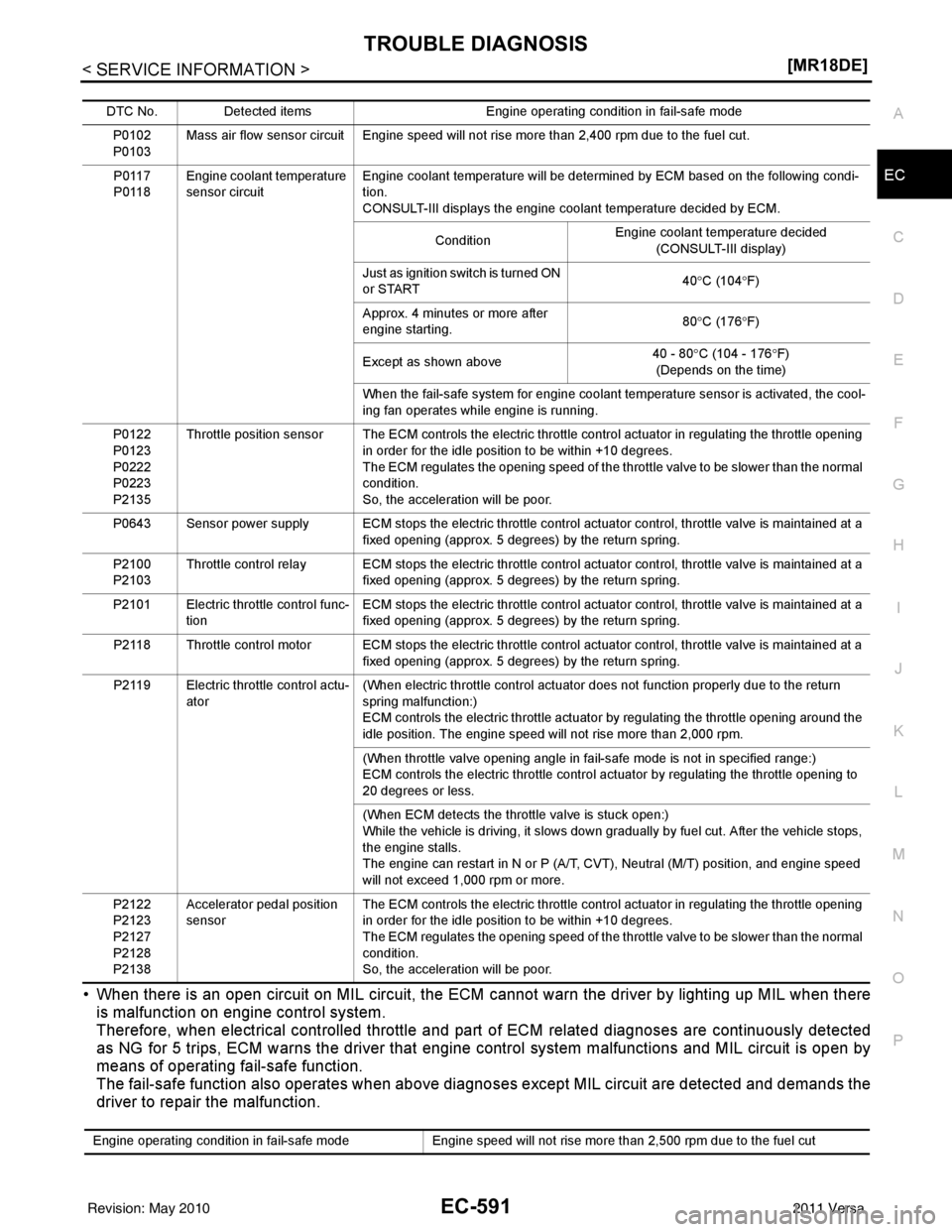
• When there is an open circuit on MIL circuit, the ECM c
annot warn the driver by lighting up MIL when there
is malfunction on engine control system.
Therefore, when electrical controlled throttle and pa rt of ECM related diagnoses are continuously detected
as NG for 5 trips, ECM warns the driver that engine control system malfunctions and MIL circuit is open by
means of operating fail-safe function.
The fail-safe function also operates when above diagnoses except MIL circuit are detected and demands the
driver to repair the malfunction.
DTC No. Detected items Engine operating condition in fail-safe mode
P0102
P0103 Mass air flow sensor circuit Engine speed will not rise more than 2,400 rpm due to the fuel cut.
P0117
P0118 Engine coolant temperature
sensor circuit Engine coolant temperature will be determined by ECM based on the following condi-
tion.
CONSULT-III displays the engine coolant temperature decided by ECM.
Condition Engine coolant temperature decided
(CONSULT-III display)
Just as ignition switch is turned ON
or START 40
°C (104 °F)
Approx. 4 minutes or more after
engine starting. 80
°C (176 °F)
Except as shown above 40 - 80°
C (104 - 176 °F)
(Depends on the time)
When the fail-safe system for engine coolant temperature sensor is activated, the cool-
ing fan operates while engine is running.
P0122
P0123
P0222
P0223
P2135 Throttle position sensor The ECM controls the electric throttle control actuator in regulating the throttle opening
in order for the idle position to be within +10 degrees.
The ECM regulates the opening speed of the throttle valve to be slower than the normal
condition.
So, the acceleration will be poor.
P0643 Sensor power supply ECM stops the electric throttle control actuator control, throttle valve is maintained at a fixed opening (approx. 5 degrees) by the return spring.
P2100
P2103 Throttle control relay ECM stops the electric throttle control actuator control, throttle valve is maintained at a
fixed opening (approx. 5 degrees) by the return spring.
P2101 Electric throttle control func- tion ECM stops the electric throttle control actuator control, throttle valve is maintained at a
fixed opening (approx. 5 degrees) by the return spring.
P2118 Throttle control motor ECM stops the electric throttle control actuator control, throttle valve is maintained at a fixed opening (approx. 5 degrees) by the return spring.
P2119 Electric throttle control actu- ator (When electric throttle control actuator does not function properly due to the return
spring malfunction:)
ECM controls the electric throttle actuator by regulating the throttle opening around the
idle position. The engine speed will not rise more than 2,000 rpm.
(When throttle valve opening angle in fail-safe mode is not in specified range:)
ECM controls the electric throttle control ac
tuator by regulating the throttle opening to
20 degrees or less.
(When ECM detects the throttle valve is stuck open:)
While the vehicle is driving, it slows down gradually by fuel cut. After the vehicle stops,
the engine stalls.
The engine can restart in N or P (A/T, CVT), Neutral (M/T) position, and engine speed
will not exceed 1,000 rpm or more.
P2122
P2123
P2127
P2128
P2138 Accelerator pedal position
sensor
The ECM controls the electric throttle control actuator in regulating the throttle opening
in order for the idle position to be within +10 degrees.
The ECM regulates the opening speed of the throttle valve to be slower than the normal
condition.
So, the acceleration will be poor.
Engine operating condition in fail-safe mode
Engine speed will not rise more than 2,500 rpm due to the fuel cut
Revision: May 2010 2011 Versa
Page 1940 of 3787
EC-646
< SERVICE INFORMATION >[MR18DE]
DTC P0011 IVT CONTROL
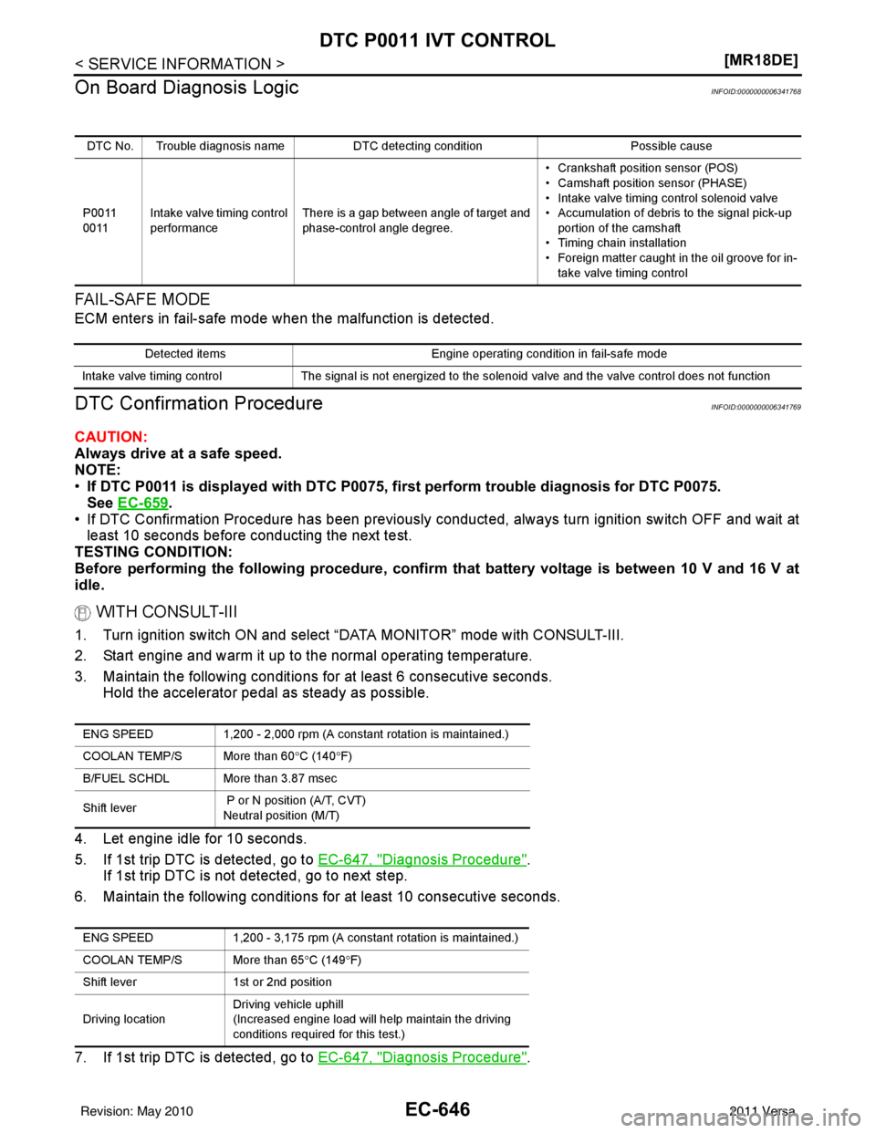
On Board Diagn osis Logic
INFOID:0000000006341768
FA I L - S A F E M O D E
ECM enters in fail-safe mode when the malfunction is detected.
DTC Confirmation ProcedureINFOID:0000000006341769
CAUTION:
Always drive at a safe speed.
NOTE:
•If DTC P0011 is displayed with DTC P0075, first perform trouble diagnosis for DTC P0075.
See EC-659
.
• If DTC Confirmation Procedure has been previously conducted, always turn ignition switch OFF and wait at
least 10 seconds before conducting the next test.
TESTING CONDITION:
Before performing the following procedure, confi rm that battery voltage is between 10 V and 16 V at
idle.
WITH CONSULT-III
1. Turn ignition switch ON and select “DATA MONITOR” mode with CONSULT-III.
2. Start engine and warm it up to the normal operating temperature.
3. Maintain the following conditions for at least 6 consecutive seconds. Hold the accelerator pedal as steady as possible.
4. Let engine idle for 10 seconds.
5. If 1st trip DTC is detected, go to EC-647, "
Diagnosis Procedure".
If 1st trip DTC is not detected, go to next step.
6. Maintain the following conditions for at least 10 consecutive seconds.
7. If 1st trip DTC is detected, go to EC-647, "
Diagnosis Procedure".
DTC No. Trouble diagnosis name DTC detecting condition Possible cause
P0011
0011 Intake valve timing control
performance There is a gap between angle of target and
phase-control angle degree. • Crankshaft position sensor (POS)
• Camshaft position
sensor (PHASE)
• Intake valve timing control solenoid valve
• Accumulation of debris to the signal pick-up portion of the camshaft
• Timing chain installation
• Foreign matter caught in the oil groove for in- take valve timing control
Detected items Engine operating condition in fail-safe mode
Intake valve timing control The signal is not energized to the solenoid valve and the valve control does not function
ENG SPEED1,200 - 2,000 rpm (A constant rotati on is maintained.)
COOLAN TEMP/S More than 60 °C (140 °F)
B/FUEL SCHDL More than 3.87 msec
Shift lever P or N position (A/T, CVT)
Neutral position (M/T)
ENG SPEED 1,200 - 3,175 rpm (A constant rotation is maintained.)
COOLAN TEMP/S More than 65 °C (149 °F)
Shift lever 1st or 2nd position
Driving location Driving vehicle uphill
(Increased engine load will help maintain the driving
conditions required for this test.)
Revision: May 2010
2011 Versa
Page 1998 of 3787
EC-704
< SERVICE INFORMATION >[MR18DE]
DTC P0130 A/F SENSOR 1
DTC P0130 A/F SENSOR 1
Component DescriptionINFOID:0000000006341859
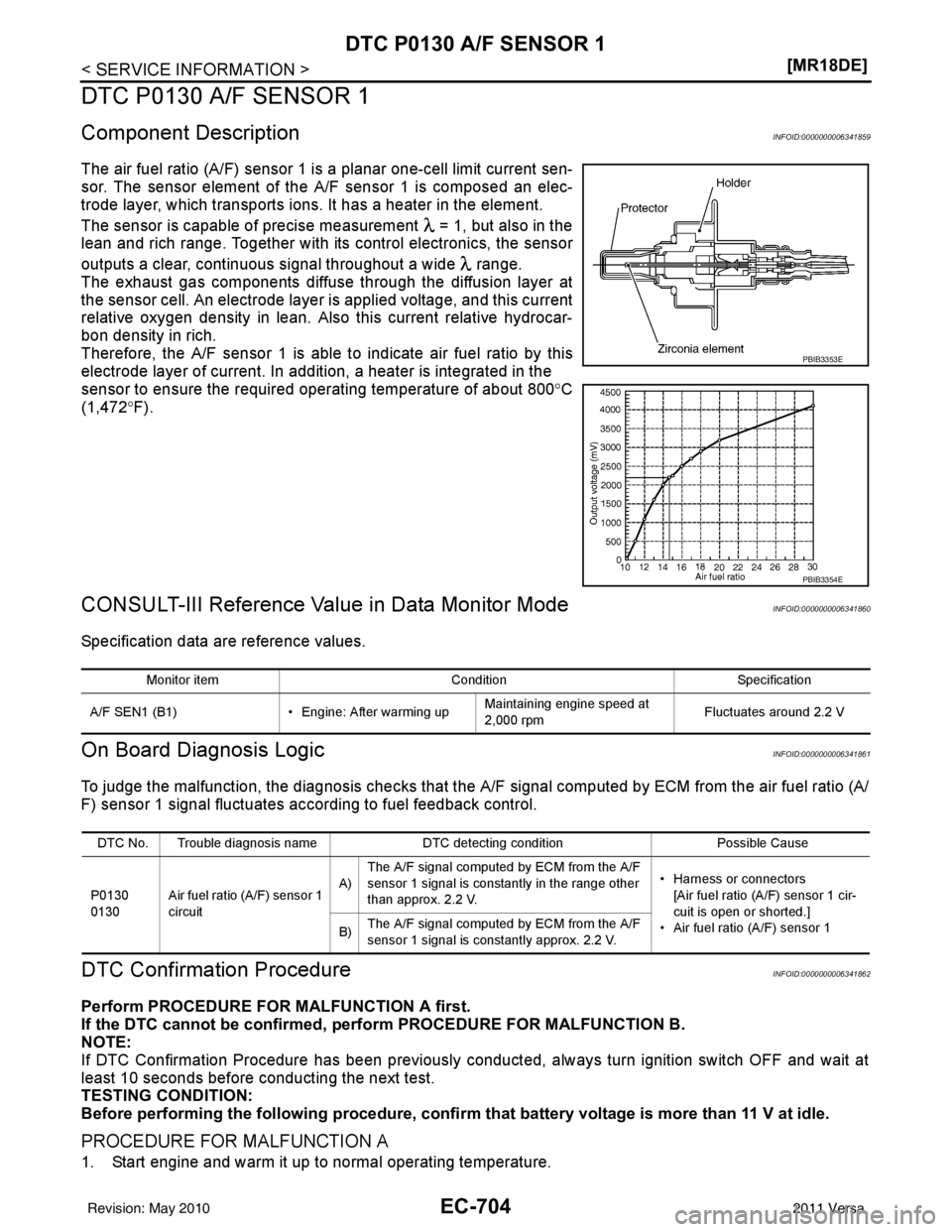
The air fuel ratio (A/F) sensor 1 is a planar one-cell limit current sen-
sor. The sensor element of the
A/F sensor 1 is composed an elec-
trode layer, which transports ions. It has a heater in the element.
The sensor is capable of precise measurement = 1, but also in the
lean and rich range. Together with its control electronics, the sensor
outputs a clear, continuous signal throughout a wide range.
The exhaust gas components diffuse through the diffusion layer at
the sensor cell. An electrode layer is applied voltage, and this current
relative oxygen density in lean. Also this current relative hydrocar-
bon density in rich.
Therefore, the A/F sensor 1 is able to indicate air fuel ratio by this
electrode layer of current. In addition, a heater is integrated in the
sensor to ensure the required operating temperature of about 800° C
(1,472° F).
CONSULT-III Reference Value in Data Monitor ModeINFOID:0000000006341860
Specification data are reference values.
On Board Diagn osis LogicINFOID:0000000006341861
To judge the malfunction, the diagnosis c hecks that the A/F signal computed by ECM from the air fuel ratio (A/
F) sensor 1 signal fluctuates ac cording to fuel feedback control.
DTC Confirmation ProcedureINFOID:0000000006341862
Perform PROCEDURE FOR MALFUNCTION A first.
If the DTC cannot be confirmed, perform PROCEDURE FOR MALFUNCTION B.
NOTE:
If DTC Confirmation Procedure has been previously conducted, always turn ignition switch OFF and wait at
least 10 seconds before conducting the next test.
TESTING CONDITION:
Before performing the following procedure, confirm that battery voltage is more than 11 V at idle.
PROCEDURE FOR MALFUNCTION A
1. Start engine and warm it up to normal operating temperature.
PBIB3353E
PBIB3354E
Monitor itemConditionSpecification
A/F SEN1 (B1) • Engine: After warming upMaintaining engine speed at
2,000 rpm Fluctuates around 2.2 V
DTC No. Trouble diagnosis name
DTC detecting conditionPossible Cause
P0130
0130 Air fuel ratio (A/F) sensor 1
circuit A)
The A/F signal computed by ECM from the A/F
sensor 1 signal is constantly in the range other
than approx. 2.2 V. • Harness or connectors
[Air fuel ratio (A/F) sensor 1 cir-
cuit is open or shorted.]
• Air fuel ratio (A/F) sensor 1
B) The A/F signal computed by ECM from the A/F
sensor 1 signal is constantly approx. 2.2 V.
Revision: May 2010
2011 Versa
Page 2004 of 3787
EC-710
< SERVICE INFORMATION >[MR18DE]
DTC P0131 A/F SENSOR 1
DTC P0131 A/F SENSOR 1
Component DescriptionINFOID:0000000006341867
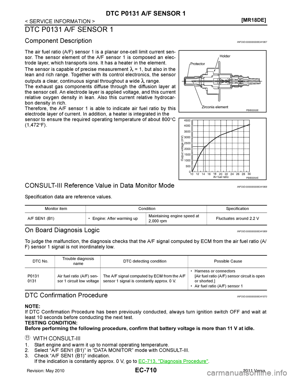
The air fuel ratio (A/F) sensor 1 is a planar one-cell limit current sen-
sor. The sensor element of the
A/F sensor 1 is composed an elec-
trode layer, which transports ions. It has a heater in the element.
The sensor is capable of precise measurement = 1, but also in the
lean and rich range. Together with its control electronics, the sensor
outputs a clear, continuous signal throughout a wide range.
The exhaust gas components diffuse through the diffusion layer at
the sensor cell. An electrode layer is applied voltage, and this current
relative oxygen density in lean. Also this current relative hydrocar-
bon density in rich.
Therefore, the A/F sensor 1 is able to indicate air fuel ratio by this
electrode layer of current. In addition, a heater is integrated in the
sensor to ensure the required operating temperature of about 800° C
(1,472° F).
CONSULT-III Reference Value in Data Monitor ModeINFOID:0000000006341868
Specification data are reference values.
On Board Diagn osis LogicINFOID:0000000006341869
To judge the malfunction, the diagnosis c hecks that the A/F signal computed by ECM from the air fuel ratio (A/
F) sensor 1 signal is not inordinately low.
DTC Confirmation ProcedureINFOID:0000000006341870
NOTE:
If DTC Confirmation Procedure has been previously conducted, always turn ignition switch OFF and wait at
least 10 seconds before conducting the next test.
TESTING CONDITION:
Before performing the following procedure, confirm that battery voltage is more than 11 V at idle.
WITH CONSULT-III
1. Start engine and warm it up to normal operating temperature.
2. Select “A/F SEN1 (B1)” in “DATA MONITOR” mode with CONSULT-III.
3. Check “A/F SEN1 (B1)” indication.
If the indication is constantly approx. 0 V, go to EC-713, "
Diagnosis Procedure".
PBIB3353E
PBIB3354E
Monitor item ConditionSpecification
A/F SEN1 (B1) • Engine: After warming upMaintaining engine speed at
2,000 rpm Fluctuates around 2.2 V
DTC No.Trouble diagnosis
name DTC detecting condition
Possible Cause
P0131
0131 Air fuel ratio (A/F) sen-
sor 1 circuit low voltage The A/F signal computed by ECM from the A/F
sensor 1 signal is constantly approx. 0 V. • Harness or connectors
[Air fuel ratio (A/F) sensor circuit is open
or shorted.]
• Air fuel ratio (A/F) sensor 1
Revision: May 2010 2011 Versa
Page 2010 of 3787
EC-716
< SERVICE INFORMATION >[MR18DE]
DTC P0132 A/F SENSOR 1
DTC P0132 A/F SENSOR 1
Component DescriptionINFOID:0000000006341874
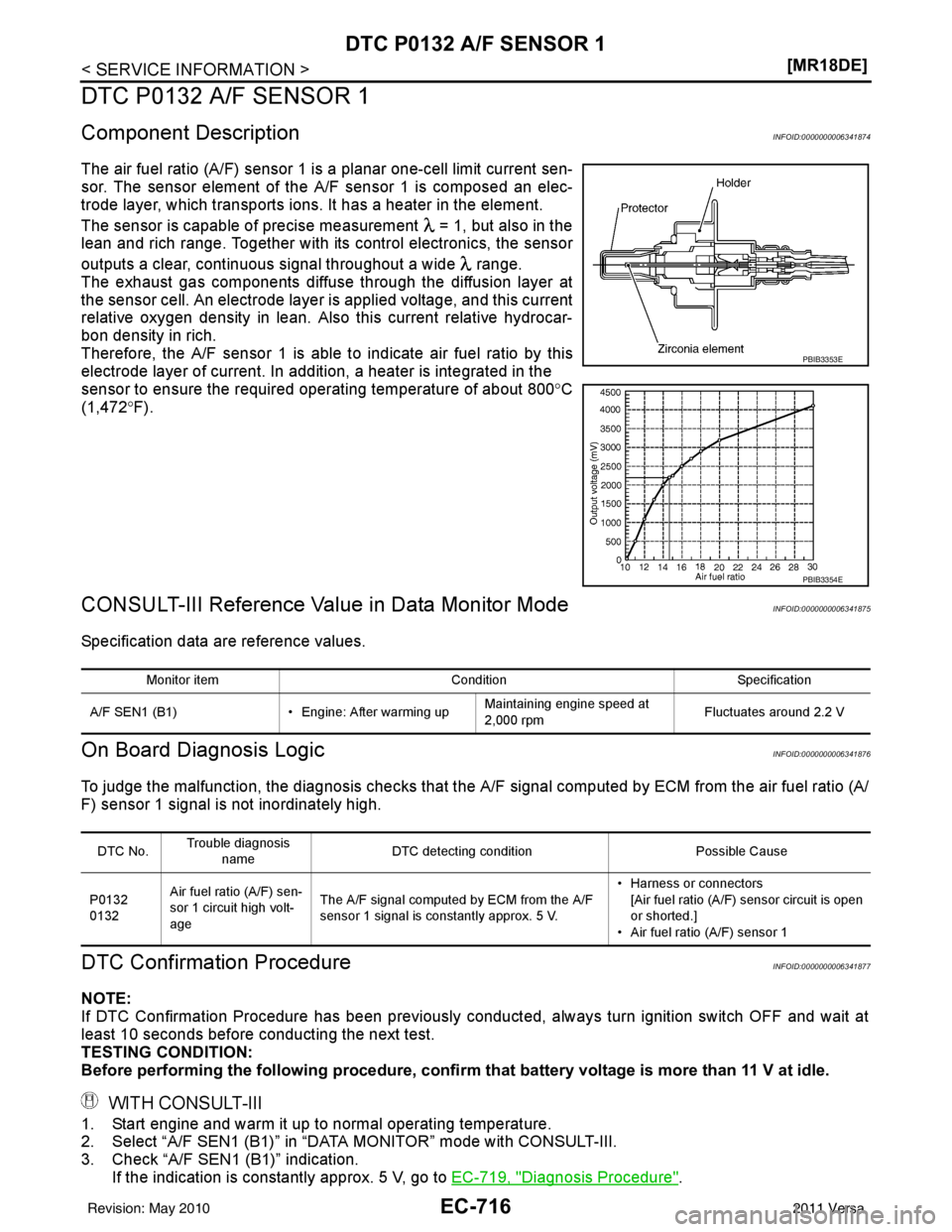
The air fuel ratio (A/F) sensor 1 is a planar one-cell limit current sen-
sor. The sensor element of the
A/F sensor 1 is composed an elec-
trode layer, which transports ions. It has a heater in the element.
The sensor is capable of precise measurement = 1, but also in the
lean and rich range. Together with its control electronics, the sensor
outputs a clear, continuous signal throughout a wide range.
The exhaust gas components diffuse through the diffusion layer at
the sensor cell. An electrode layer is applied voltage, and this current
relative oxygen density in lean. Also this current relative hydrocar-
bon density in rich.
Therefore, the A/F sensor 1 is able to indicate air fuel ratio by this
electrode layer of current. In addition, a heater is integrated in the
sensor to ensure the required operating temperature of about 800° C
(1,472° F).
CONSULT-III Reference Value in Data Monitor ModeINFOID:0000000006341875
Specification data are reference values.
On Board Diagn osis LogicINFOID:0000000006341876
To judge the malfunction, the diagnosis c hecks that the A/F signal computed by ECM from the air fuel ratio (A/
F) sensor 1 signal is not inordinately high.
DTC Confirmation ProcedureINFOID:0000000006341877
NOTE:
If DTC Confirmation Procedure has been previously conducted, always turn ignition switch OFF and wait at
least 10 seconds before conducting the next test.
TESTING CONDITION:
Before performing the following procedure, confirm that battery voltage is more than 11 V at idle.
WITH CONSULT-III
1. Start engine and warm it up to normal operating temperature.
2. Select “A/F SEN1 (B1)” in “DATA MONITOR” mode with CONSULT-III.
3. Check “A/F SEN1 (B1)” indication.
If the indication is constantly approx. 5 V, go to EC-719, "
Diagnosis Procedure".
PBIB3353E
PBIB3354E
Monitor item ConditionSpecification
A/F SEN1 (B1) • Engine: After warming upMaintaining engine speed at
2,000 rpm Fluctuates around 2.2 V
DTC No.Trouble diagnosis
name DTC detecting condition
Possible Cause
P0132
0132 Air fuel ratio (A/F) sen-
sor 1 circuit high volt-
age The A/F signal computed by ECM from the A/F
sensor 1 signal is constantly approx. 5 V. • Harness or connectors
[Air fuel ratio (A/F) sensor circuit is open
or shorted.]
• Air fuel ratio (A/F) sensor 1
Revision: May 2010 2011 Versa
Page 2044 of 3787
EC-750
< SERVICE INFORMATION >[MR18DE]
DTC P014C, P014D A/F SENSOR 1
DTC P014C, P014D A/F SENSOR 1
Component DescriptionINFOID:0000000006341908
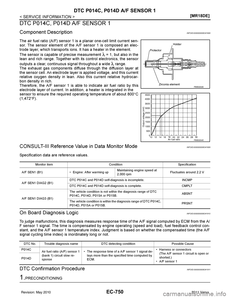
The air fuel ratio (A/F) sensor 1 is a planar one-cell limit current sen-
sor. The sensor element of the
A/F sensor 1 is composed an elec-
trode layer, which transports ions. It has a heater in the element.
The sensor is capable of precise measurement = 1, but also in the
lean and rich range. Together with its control electronics, the sensor
outputs a clear, continuous signal throughout a wide range.
The exhaust gas components diffuse through the diffusion layer at
the sensor cell. An electrode layer is applied voltage, and this current
relative oxygen density in lean. Also this current relative hydrocar-
bon density in rich.
Therefore, the A/F sensor 1 is able to indicate air fuel ratio by this
electrode layer of current. In addition, a heater is integrated in the
sensor to ensure the required operating temperature of about 800° C
(1,472° F).
CONSULT-III Reference Value in Data Monitor ModeINFOID:0000000006341909
Specification data are reference values.
On Board Diagn osis LogicINFOID:0000000006341910
To judge malfunctions, this diagnosis measures response time of the A/F signal computed by ECM from the A/
F sensor 1 signal. The time is compensated by engi ne operating (speed and load), fuel feedback control con-
stant, and the A/F sensor 1 temperature index. Judgment is based on whether the compensated time (the A/F
signal cycling time index) is inordinately long or not.
DTC Confirmation ProcedureINFOID:0000000006341911
1.PRECONDITIONING
PBIB3353E
PBIB3354E
Monitor item ConditionSpecification
A/F SEN1 (B1) • Engine: After warming upMaintaining engine speed at
2,000 rpm Fluctuates around 2.2 V
A/F SEN1 DIAG2 (B1) DTC P014C and P014D self-diagnosis is incomplete.
INCMP
DTC P014C and P014D self-diagnosis is complete. CMPLT
A/F SEN1 DIAG3 (B1) The vehicle condition is not within the diagnosis range of DTC
P014C, P014D, P015A or P015B.
ABSNT
The vehicle condition is within the diagnosis range of DTC P014C,
P014D, P015A or P015B. PRSNT
DTC No. Trouble diagnosis name
DTC detecting conditionPossible Cause
P014C Air fuel ratio (A/F) sensor 1
(bank 1) circuit slow re-
sponse • The response time of a A/F sensor 1 signal de-
lays more than the specified time computed by
ECM. • Harness or connectors
(The A/F sensor 1 circuit is open or
shorted.)
• A/F sensor 1
P014D
Revision: May 2010
2011 Versa