2011 NISSAN LATIO key battery
[x] Cancel search: key batteryPage 2733 of 3787

SERVICE INFORMATION FOR ELECTRICAL INCIDENTGI-29
< SERVICE INFORMATION >
C
DE
F
G H
I
J
K L
M B
GI
N
O P
• Close the relay and probe at the solenoid. voltage; open is further down the circuit than the solenoid.
no voltage; open is between relay and solenoid (point C).
Any powered circuit can be diagnosed using the approach in the previous example.
Testing for “Shorts” in the Circuit
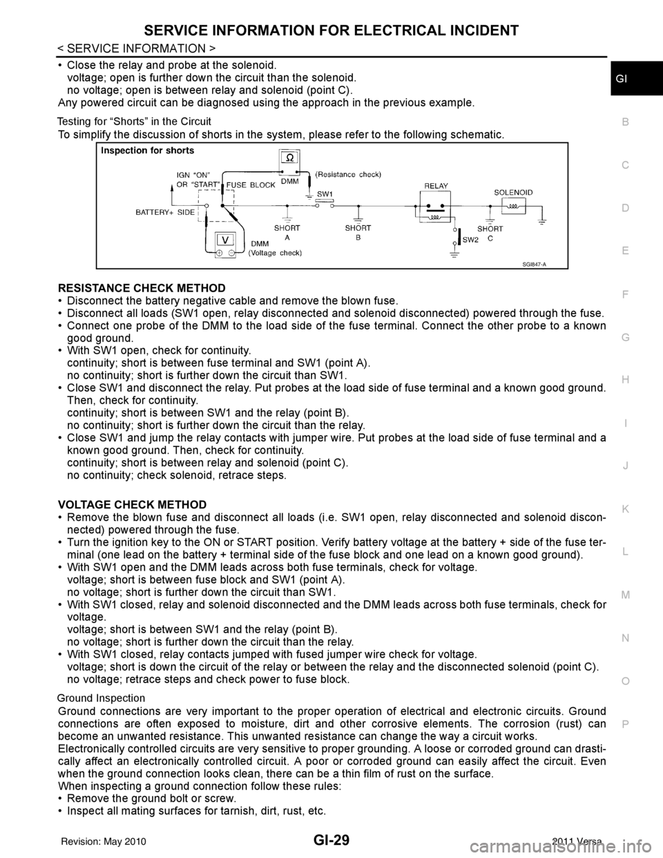
To simplify the discussion of shorts in the system, please refer to the following schematic.
RESISTANCE CHECK METHOD
• Disconnect the battery negative cable and remove the blown fuse.
• Disconnect all loads (SW1 open, relay disconnected and solenoid disconnected) powered through the fuse.
• Connect one probe of the DMM to the load side of the fuse terminal. Connect the other probe to a known
good ground.
• With SW1 open, check for continuity.
continuity; short is between fuse terminal and SW1 (point A).
no continuity; short is further down the circuit than SW1.
• Close SW1 and disconnect the relay. Put probes at the load side of fuse terminal and a known good ground.
Then, check for continuity.
continuity; short is between SW1 and the relay (point B).
no continuity; short is further down the circuit than the relay.
• Close SW1 and jump the relay contacts with jumper wir e. Put probes at the load side of fuse terminal and a
known good ground. Then, check for continuity.
continuity; short is between relay and solenoid (point C).
no continuity; check solenoid, retrace steps.
VOLTAGE CHECK METHOD
• Remove the blown fuse and disconnect all loads (i .e. SW1 open, relay disconnected and solenoid discon-
nected) powered through the fuse.
• Turn the ignition key to the ON or START position. Veri fy battery voltage at the battery + side of the fuse ter-
minal (one lead on the battery + terminal side of the fuse block and one lead on a known good ground).
• With SW1 open and the DMM leads across both fuse terminals, check for voltage.
voltage; short is between fuse block and SW1 (point A).
no voltage; short is further down the circuit than SW1.
• With SW1 closed, relay and solenoid disconnected and the DMM leads across both fuse terminals, check for voltage.
voltage; short is between SW1 and the relay (point B).
no voltage; short is further down the circuit than the relay.
• With SW1 closed, relay contacts jumped with fused jumper wire check for voltage.
voltage; short is down the circuit of the relay or between the relay and the disconnected solenoid (point C).
no voltage; retrace steps and check power to fuse block.
Ground Inspection
Ground connections are very important to the proper oper ation of electrical and electronic circuits. Ground
connections are often exposed to moisture, dirt and other corrosive elements. The corrosion (rust) can
become an unwanted resistance. This unwanted resistance can change the way a circuit works.
Electronically controlled circuits are very sensitive to proper grounding. A loose or corroded ground can drasti-
cally affect an electronically controlled circuit. A poor or corroded ground can easily affect the circuit. Even
when the ground connection looks clean, there can be a thin film of rust on the surface.
When inspecting a ground connection follow these rules:
• Remove the ground bolt or screw.
• Inspect all mating surfaces for tarnish, dirt, rust, etc.
SGI847-A
Revision: May 2010 2011 Versa
Page 2744 of 3787

GI-40
< SERVICE INFORMATION >
TOW TRUCK TOWING
TOW TRUCK TOWING
Tow Truck TowingINFOID:0000000005929736
CAUTION:
• Never tow a CVT model with the rear wheels raised and the front wheels on the ground. This may
cause serious and expensive damage to the transaxle. If it is necessary to tow the vehicle with the
rear wheels raised, always use towi ng dollies under the front wheels.
• Never tow a CVT model from the rear (that is backw ard) with four wheels on the ground. This may
cause serious and expensive damage to the transaxle.
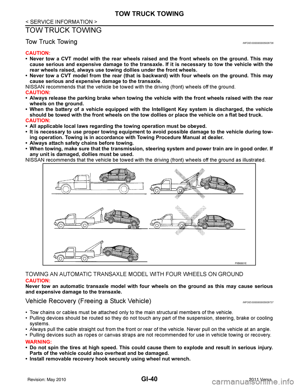
NISSAN recommends that the vehicle be towed with the driving (front) wheels off the ground.
CAUTION:
• Always release the parking brake when towing the veh icle with the front wheels raised with the rear
wheels on the ground.
• When the battery of a vehicle equipped with th e Intelligent Key system is discharged, the vehicle
should be towed with the front wheels on the tow dollies or place the vehicle on a flat bed truck.
CAUTION:
• All applicable local laws regarding the towing operation must be obeyed.
• It is necessary to use proper towi ng equipment to avoid possible damage to the vehicle during tow-
ing operation. To wing is in accordance with Towing Procedure Manual at dealer.
• Always attach safety chains before towing.
• When towing, make sure that the transmission, steering system and power train are in good order. If
any unit is damaged, dollies must be used.
NISSAN recommends that the vehicle be towed with the driving (front) wheels off the ground as illustrated.
TOWING AN AUTOMATIC TRANSAXLE MODEL WITH FOUR WHEELS ON GROUND
CAUTION:
Never tow an automatic transaxle model with four wheels on the ground as this may cause serious
and expensive damage to the transaxle.
Vehicle Recovery (Freeing a Stuck Vehicle)INFOID:0000000005929737
• Tow chains or cables must be attached only to the main structural members of the vehicle.
• Pulling devices should be routed so they do not touch any part of the suspension, steering, brake or cooling
systems.
• Always pull the cable straight out from the front or r ear of the vehicle. Never pull on the vehicle at an angle.
• Pulling devices such as ropes or canvas straps are not recommended for use in vehicle towing or recovery.
WARNING:
• Do not spin the tires at high sp eed. This could cause them to explode and result in serious injury.
Parts of the vehicle could also overheat and be damaged.
• Install removable recovery hook securely using wheel nut wrench.
PIIB6801E
Revision: May 2010 2011 Versa
Page 2757 of 3787

PRECAUTIONSGW-3
< SERVICE INFORMATION >
C
DE
F
G H
J
K L
M A
B
GW
N
O P
SERVICE INFORMATION
PRECAUTIONS
Precaution for Supplemental Restraint System (SRS) "AIR BAG" and "SEAT BELT
PRE-TENSIONER"
INFOID:0000000005929457
The Supplemental Restraint System such as “AIR BAG” and “SEAT BELT PRE-TENSIONER”, used along
with a front seat belt, helps to reduce the risk or severi ty of injury to the driver and front passenger for certain
types of collision. This system includes seat belt switch inputs and dual stage front air bag modules. The SRS
system uses the seat belt switches to determine the front air bag deployment, and may only deploy one front
air bag, depending on the severity of a collision and w hether the front occupants are belted or unbelted.
Information necessary to service the system safely is included in the SRS and SB section of this Service Man-
ual.
WARNING:
• To avoid rendering the SRS inoper ative, which could increase the risk of personal injury or death in
the event of a collision which would result in air bag inflation, all maintenance must be performed by
an authorized NISSAN/INFINITI dealer.
• Improper maintenance, including in correct removal and installation of the SRS can lead to personal
injury caused by unintentional act ivation of the system. For removal of Spiral Cable and Air Bag
Module, see the SRS section.
• Do not use electrical test equipm ent on any circuit related to the SRS unless instructed to in this
Service Manual. SRS wiring harnesses can be identi fied by yellow and/or orange harnesses or har-
ness connectors.
PRECAUTIONS WHEN USING POWER TOOLS (AIR OR ELECTRIC) AND HAMMERS
WARNING:
• When working near the Airbag Diagnosis Sensor Un it or other Airbag System sensors with the Igni-
tion ON or engine running, DO NOT use air or el ectric power tools or strike near the sensor(s) with a
hammer. Heavy vibration could activate the sensor( s) and deploy the air bag(s), possibly causing
serious injury.
• When using air or electric power tools or hammers, always switch the Ignition OFF, disconnect the battery, and wait at least 3 minutes before performing any service.
Precaution Necessary for Steering Wheel Rotation After Battery Disconnect
INFOID:0000000005929458
NOTE:
• This Procedure is applied only to models with Intelligent Key system and NATS (NISSAN ANTI-THEFT SYS-
TEM).
• Remove and install all control units after disconnecti ng both battery cables with the ignition knob in the
″ LOCK ″ position.
• Always use CONSULT-III to perform self-diagnosis as a part of each function inspection after finishing work.
If DTC is detected, perform trouble diagnosis according to self-diagnostic results.
For models equipped with the Intelligent Key system and NATS , an electrically controlled steering lock mech-
anism is adopted on the key cylinder.
For this reason, if the battery is disconnected or if the battery is discharged, the steering wheel will lock and
steering wheel rotation will become impossible.
If steering wheel rotation is required when battery power is interrupted, follow the procedure below before
starting the repair operation.
OPERATION PROCEDURE
1. Connect both battery cables. NOTE:
Supply power using jumper cables if battery is discharged.
2. Use the Intelligent Key or mechanical key to turn the ignition switch to the ″ACC ″ position. At this time, the
steering lock will be released.
3. Disconnect both battery cables. The steering lock will remain released and the steering wheel can be
rotated.
4. Perform the necessary repair operation.
Revision: May 2010 2011 Versa
Page 2823 of 3787

IP-2
< PRECAUTION >
PRECAUTIONS
PRECAUTION
PRECAUTIONS
Precaution for Supplemental Restraint System (SRS) "AIR BAG" and "SEAT BELT
PRE-TENSIONER"
INFOID:0000000005929584
The Supplemental Restraint System such as “A IR BAG” and “SEAT BELT PRE-TENSIONER”, used along
with a front seat belt, helps to reduce the risk or severity of injury to the driver and front passenger for certain
types of collision. This system includes seat belt switch inputs and dual stage front air bag modules. The SRS
system uses the seat belt switches to determine the front air bag deployment, and may only deploy one front
air bag, depending on the severity of a collision and w hether the front occupants are belted or unbelted.
Information necessary to service the system safely is included in the SRS and SB section of this Service Man-
ual.
WARNING:
• To avoid rendering the SRS inopera tive, which could increase the risk of personal injury or death in
the event of a collision which would result in air bag inflation, all maintenance must be performed by
an authorized NISSAN/INFINITI dealer.
• Improper maintenance, including in correct removal and installation of the SRS, can lead to personal
injury caused by unintent ional activation of the system. For re moval of Spiral Cable and Air Bag
Module, see the SRS section.
• Do not use electrical test equipmen t on any circuit related to the SRS unless instructed to in this
Service Manual. SRS wiring harn esses can be identified by yellow and/or orange harnesses or har-
ness connectors.
PRECAUTIONS WHEN USING POWER TOOLS (AIR OR ELECTRIC) AND HAMMERS
WARNING:
• When working near the Airbag Diagnosis Sensor Unit or other Airbag System sensors with the Igni-
tion ON or engine running, DO NOT use air or electri c power tools or strike near the sensor(s) with a
hammer. Heavy vibration could activate the sensor( s) and deploy the air bag(s), possibly causing
serious injury.
• When using air or electric power tools or hammers , always switch the Ignition OFF, disconnect the
battery, and wait at least 3 minu tes before performing any service.
Precaution Necessary for Steering W heel Rotation After Battery Disconnect
INFOID:0000000005929585
NOTE:
• This Procedure is applied only to models with Intelligent Key system and NATS (NISSAN ANTI-THEFT SYS-
TEM).
• Remove and install all control units after disconnecting both battery cables with the ignition knob in the
″LOCK ″ position.
• Always use CONSULT-III to perform self-diagnosis as a part of each function inspection after finishing work.
If DTC is detected, perform trouble diagnosis according to self-diagnostic results.
For models equipped with the Intelligent Key system and NATS, an electrically controlled steering lock mech-
anism is adopted on the key cylinder.
For this reason, if the battery is disconnected or if the battery is discharged, the steering wheel will lock and
steering wheel rotation will become impossible.
If steering wheel rotation is required when battery pow er is interrupted, follow the procedure below before
starting the repair operation.
OPERATION PROCEDURE
1. Connect both battery cables. NOTE:
Supply power using jumper cables if battery is discharged.
2. Use the Intelligent Key or mechanical key to turn the ignition switch to the ″ACC ″ position. At this time, the
steering lock will be released.
3. Disconnect both battery cables. The steering lock will remain released and the steering wheel can be rotated.
4. Perform the necessary repair operation.
Revision: May 2010 2011 Versa
Page 2886 of 3787
![NISSAN LATIO 2011 Service Repair Manual LAN-40
< SERVICE INFORMATION >[CAN]
I-KEY BRANCH LINE CIRCUIT
I-KEY BRANCH LINE CIRCUIT
Diagnosis ProcedureINFOID:0000000005928547
1.CHECK CONNECTOR
1. Turn the ignition switch OFF.
2. Disconnect the NISSAN LATIO 2011 Service Repair Manual LAN-40
< SERVICE INFORMATION >[CAN]
I-KEY BRANCH LINE CIRCUIT
I-KEY BRANCH LINE CIRCUIT
Diagnosis ProcedureINFOID:0000000005928547
1.CHECK CONNECTOR
1. Turn the ignition switch OFF.
2. Disconnect the](/manual-img/5/57357/w960_57357-2885.png)
LAN-40
< SERVICE INFORMATION >[CAN]
I-KEY BRANCH LINE CIRCUIT
I-KEY BRANCH LINE CIRCUIT
Diagnosis ProcedureINFOID:0000000005928547
1.CHECK CONNECTOR
1. Turn the ignition switch OFF.
2. Disconnect the battery cable from the negative terminal.
3. Check the terminals and connectors of the Inte lligent Key unit for damage, bend and loose connection
(unit side and connector side).
Is the inspection result normal?
YES >> GO TO 2.
NO >> Repair the terminal and connector.
2.CHECK HARNESS FOR OPEN CIRCUIT
1. Disconnect the connector of Intelligent Key unit.
2. Check the resistance between the Intelligent Key unit harness connector terminals.
Is the measurement value within the specification?
YES >> GO TO 3.
NO >> Repair the Intelligent Key unit branch line.
3.CHECK POWER SUPPLY AND GROUND CIRCUIT
Check the power supply and the ground circuit of the Intelligent Key unit. Refer to BL-126, "
Power Supply and
Ground Circuit Inspection".
Is the inspection result normal?
YES (Present error)>>Replace the Intelligent Key unit. Refer to BL-158, "Removal and Installation of Intelli-
gent Key Unit".
YES (Past error)>>Error was detected in the Intelligent Key unit branch line.
NO >> Repair the power supply and the ground circuit.
Intelligent Key unit harness connector Resistance (Ω)
Connector No. Terminal No.
M52 23Approx. 54 – 66
Revision: May 2010 2011 Versa
Page 3000 of 3787
![NISSAN LATIO 2011 Service Repair Manual LAN-154
< SERVICE INFORMATION >[CAN SYSTEM (TYPE 11)]
I-KEY BRANCH LINE CIRCUIT
I-KEY BRANCH LINE CIRCUIT
Diagnosis ProcedureINFOID:0000000005928650
1.CHECK CONNECTOR
1. Turn the ignition switch OFF.
NISSAN LATIO 2011 Service Repair Manual LAN-154
< SERVICE INFORMATION >[CAN SYSTEM (TYPE 11)]
I-KEY BRANCH LINE CIRCUIT
I-KEY BRANCH LINE CIRCUIT
Diagnosis ProcedureINFOID:0000000005928650
1.CHECK CONNECTOR
1. Turn the ignition switch OFF.](/manual-img/5/57357/w960_57357-2999.png)
LAN-154
< SERVICE INFORMATION >[CAN SYSTEM (TYPE 11)]
I-KEY BRANCH LINE CIRCUIT
I-KEY BRANCH LINE CIRCUIT
Diagnosis ProcedureINFOID:0000000005928650
1.CHECK CONNECTOR
1. Turn the ignition switch OFF.
2. Disconnect the battery cable from the negative terminal.
3. Check the terminals and connectors of the Inte lligent Key unit for damage, bend and loose connection
(unit side and connector side).
Is the inspection result normal?
YES >> GO TO 2.
NO >> Repair the terminal and connector.
2.CHECK HARNESS FOR OPEN CIRCUIT
1. Disconnect the connector of Intelligent Key unit.
2. Check the resistance between the Intelligent Key unit harness connector terminals.
Is the measurement value within the specification?
YES >> GO TO 3.
NO >> Repair the Intelligent Key unit branch line.
3.CHECK POWER SUPPLY AND GROUND CIRCUIT
Check the power supply and the ground circuit of the Intelligent Key unit. Refer to BL-126, "
Power Supply and
Ground Circuit Inspection".
Is the inspection result normal?
YES (Present error)>>Replace the Intelligent Key unit. Refer to BL-158, "Removal and Installation of Intelli-
gent Key Unit".
YES (Past error)>>Error was detected in the Intelligent Key unit branch line.
NO >> Repair the power supply and the ground circuit.
Intelligent Key unit harness connector Resistance (Ω)
Connector No. Terminal No.
M52 23Approx. 54 – 66
Revision: May 2010 2011 Versa
Page 3025 of 3787
![NISSAN LATIO 2011 Service Repair Manual I-KEY BRANCH LINE CIRCUITLAN-179
< SERVICE INFORMATION > [CAN SYSTEM (TYPE 13)]
C
D
E
F
G H
I
J
L
M A
B
LAN
N
O P
I-KEY BRANCH LINE CIRCUIT
Diagnosis ProcedureINFOID:0000000005928673
1.CHECK CONNECTOR NISSAN LATIO 2011 Service Repair Manual I-KEY BRANCH LINE CIRCUITLAN-179
< SERVICE INFORMATION > [CAN SYSTEM (TYPE 13)]
C
D
E
F
G H
I
J
L
M A
B
LAN
N
O P
I-KEY BRANCH LINE CIRCUIT
Diagnosis ProcedureINFOID:0000000005928673
1.CHECK CONNECTOR](/manual-img/5/57357/w960_57357-3024.png)
I-KEY BRANCH LINE CIRCUITLAN-179
< SERVICE INFORMATION > [CAN SYSTEM (TYPE 13)]
C
D
E
F
G H
I
J
L
M A
B
LAN
N
O P
I-KEY BRANCH LINE CIRCUIT
Diagnosis ProcedureINFOID:0000000005928673
1.CHECK CONNECTOR
1. Turn the ignition switch OFF.
2. Disconnect the battery cabl e from the negative terminal.
3. Check the terminals and connectors of the Intelligent Key unit for damage, bend and loose connection (unit side and connector side).
Is the inspection result normal?
YES >> GO TO 2.
NO >> Repair the terminal and connector.
2.CHECK HARNESS FOR OPEN CIRCUIT
1. Disconnect the connector of Intelligent Key unit.
2. Check the resistance between the Intelli gent Key unit harness connector terminals.
Is the measurement value within the specification?
YES >> GO TO 3.
NO >> Repair the Intelligent Key unit branch line.
3.CHECK POWER SUPPLY AND GROUND CIRCUIT
Check the power supply and the ground circuit of the Intelligent Key unit. Refer to BL-126, "
Power Supply and
Ground Circuit Inspection".
Is the inspection result normal?
YES (Present error)>>Replace the Intelligent Key unit. Refer to BL-158, "Removal and Installation of Intelli-
gent Key Unit".
YES (Past error)>>Error was detected in the Intelligent Key unit branch line.
NO >> Repair the power supply and the ground circuit.
Intelligent Key unit harness connector Resistance (Ω)
Connector No. Terminal No.
M52 2 3 Approx. 54 – 66
Revision: May 2010 2011 Versa
Page 3035 of 3787

PRECAUTIONSLT-3
< SERVICE INFORMATION >
C
DE
F
G H
I
J
L
M A
B
LT
N
O P
SERVICE INFORMATION
PRECAUTIONS
Precaution for Supplemental Restraint System (SRS) "AIR BAG" and "SEAT BELT
PRE-TENSIONER"
INFOID:0000000005929026
The Supplemental Restraint System such as “AIR BAG” and “SEAT BELT PRE-TENSIONER”, used along
with a front seat belt, helps to reduce the risk or severi ty of injury to the driver and front passenger for certain
types of collision. This system includes seat belt switch inputs and dual stage front air bag modules. The SRS
system uses the seat belt switches to determine the front air bag deployment, and may only deploy one front
air bag, depending on the severity of a collision and w hether the front occupants are belted or unbelted.
Information necessary to service the system safely is included in the SRS and SB section of this Service Man-
ual.
WARNING:
• To avoid rendering the SRS inoper ative, which could increase the risk of personal injury or death in
the event of a collision which would result in air bag inflation, all maintenance must be performed by
an authorized NISSAN/INFINITI dealer.
• Improper maintenance, including in correct removal and installation of the SRS can lead to personal
injury caused by unintentional act ivation of the system. For removal of Spiral Cable and Air Bag
Module, see the SRS section.
• Do not use electrical test equipm ent on any circuit related to the SRS unless instructed to in this
Service Manual. SRS wiring harnesses can be identi fied by yellow and/or orange harnesses or har-
ness connectors.
PRECAUTIONS WHEN USING POWER TOOLS (AIR OR ELECTRIC) AND HAMMERS
WARNING:
• When working near the Airbag Diagnosis Sensor Un it or other Airbag System sensors with the Igni-
tion ON or engine running, DO NOT use air or el ectric power tools or strike near the sensor(s) with a
hammer. Heavy vibration could activate the sensor( s) and deploy the air bag(s), possibly causing
serious injury.
• When using air or electric power tools or hammers, always switch the Ignition OFF, disconnect the battery, and wait at least 3 minutes before performing any service.
Precaution Necessary for Steering Wheel Rotation After Battery Disconnect
INFOID:0000000005929027
NOTE:
• This Procedure is applied only to models with Intelligent Key system and NATS (NISSAN ANTI-THEFT SYS-
TEM).
• Remove and install all control units after disconnecti ng both battery cables with the ignition knob in the
″ LOCK ″ position.
• Always use CONSULT-III to perform self-diagnosis as a part of each function inspection after finishing work.
If DTC is detected, perform trouble diagnosis according to self-diagnostic results.
For models equipped with the Intelligent Key system and NATS , an electrically controlled steering lock mech-
anism is adopted on the key cylinder.
For this reason, if the battery is disconnected or if the battery is discharged, the steering wheel will lock and
steering wheel rotation will become impossible.
If steering wheel rotation is required when battery power is interrupted, follow the procedure below before
starting the repair operation.
OPERATION PROCEDURE
1. Connect both battery cables. NOTE:
Supply power using jumper cables if battery is discharged.
2. Use the Intelligent Key or mechanical key to turn the ignition switch to the ″ACC ″ position. At this time, the
steering lock will be released.
3. Disconnect both battery cables. The steering lock will remain released and the steering wheel can be
rotated.
4. Perform the necessary repair operation.
Revision: May 2010 2011 Versa