2011 NISSAN LATIO engine
[x] Cancel search: enginePage 3282 of 3787
![NISSAN LATIO 2011 Service Repair Manual TRANSAXLE ASSEMBLYMT-61
< SERVICE INFORMATION > [RS6F94R]
D
E
F
G H
I
J
K L
M A
B
MT
N
O P
TRANSAXLE ASSEMBLY
ComponentINFOID:0000000005929696
Removal and InstallationINFOID:0000000005929697
CAUTION:
NISSAN LATIO 2011 Service Repair Manual TRANSAXLE ASSEMBLYMT-61
< SERVICE INFORMATION > [RS6F94R]
D
E
F
G H
I
J
K L
M A
B
MT
N
O P
TRANSAXLE ASSEMBLY
ComponentINFOID:0000000005929696
Removal and InstallationINFOID:0000000005929697
CAUTION:](/manual-img/5/57357/w960_57357-3281.png)
TRANSAXLE ASSEMBLYMT-61
< SERVICE INFORMATION > [RS6F94R]
D
E
F
G H
I
J
K L
M A
B
MT
N
O P
TRANSAXLE ASSEMBLY
ComponentINFOID:0000000005929696
Removal and InstallationINFOID:0000000005929697
CAUTION:
If transaxle assembly is removed from the vehicle , always replace CSC (Concentric Slave Cylinder).
Inserted CSC returns to the origin al position when removing transaxle assembly. Dust on clutch disc
sliding parts may damage CSC seal, and may cause clutch fluid leakage.
REMOVAL
1. Drain clutch fluid and remove clutch tube from CSC. Refer to CL-13, "Removal and Installation".
CAUTION:
Do not depress clutch pedal during removal procedure.
2. Remove engine and transaxle assembly. Refer to EM-197, "
Removal and Installation".
3. Remove starter motor. Refer to SC-20, "
Removal and Installation MR18DE".
4. Remove transaxle assembly to engine bolts.
5. Separate transaxle assembly from engine.
INSTALLATION
Installation is in the reverse order of removal.
• If transaxle is removed from the v ehicle, always replace CSC. Refer to CL-13, "
Removal and Installation" .
1. LH engine mount bracket (transaxle side) 2. Transaxle assembly 3. Rear engine mount bracket
4. Washer 5. Rear torque rod Front
: Refer to MT-61, "
Removal and Installation".
SCIA7631E
Revision: May 2010 2011 Versa
Page 3283 of 3787
![NISSAN LATIO 2011 Service Repair Manual MT-62
< SERVICE INFORMATION >[RS6F94R]
TRANSAXLE ASSEMBLY
• When installing the transaxle assembly to the engine, install the
bolts as shown.
CAUTION:
When installing transaxle assembly, be careful NISSAN LATIO 2011 Service Repair Manual MT-62
< SERVICE INFORMATION >[RS6F94R]
TRANSAXLE ASSEMBLY
• When installing the transaxle assembly to the engine, install the
bolts as shown.
CAUTION:
When installing transaxle assembly, be careful](/manual-img/5/57357/w960_57357-3282.png)
MT-62
< SERVICE INFORMATION >[RS6F94R]
TRANSAXLE ASSEMBLY
• When installing the transaxle assembly to the engine, install the
bolts as shown.
CAUTION:
When installing transaxle assembly, be careful not to bring
transaxle input shaft into co ntact with clutch cover.
A: M/T to engine
B: Engine to M/T
• Bleed the air from the clutch hydraulic system. Refer to CL-9, "
Air Bleeding Procedure".
• After installation, check oil level, and check for leaks and loose mechanisms. Refer to MT-54, "
Checking M/T
Oil".
Disassembly and AssemblyINFOID:0000000005929698
COMPONENTS
Case and Housing Components
Bolt No.12
Quantity 36
Bolt length “ ” mm (in) 60 (2.36)
50 (1.97)
Tightening torque
N·m (kg-m, ft-lb) 62.0 (6.3, 46)
PCIB1786E
Revision: May 2010
2011 Versa
Page 3316 of 3787
![NISSAN LATIO 2011 Service Repair Manual SERVICE DATA AND SPECIFICATIONS (SDS)MT-95
< SERVICE INFORMATION > [RS6F94R]
D
E
F
G H
I
J
K L
M A
B
MT
N
O P
SERVICE DATA AND SPECIFICATIONS (SDS)
General SpecificationINFOID:0000000005929704
Transax NISSAN LATIO 2011 Service Repair Manual SERVICE DATA AND SPECIFICATIONS (SDS)MT-95
< SERVICE INFORMATION > [RS6F94R]
D
E
F
G H
I
J
K L
M A
B
MT
N
O P
SERVICE DATA AND SPECIFICATIONS (SDS)
General SpecificationINFOID:0000000005929704
Transax](/manual-img/5/57357/w960_57357-3315.png)
SERVICE DATA AND SPECIFICATIONS (SDS)MT-95
< SERVICE INFORMATION > [RS6F94R]
D
E
F
G H
I
J
K L
M A
B
MT
N
O P
SERVICE DATA AND SPECIFICATIONS (SDS)
General SpecificationINFOID:0000000005929704
Transaxle type RS6F94R
Engine type MR18DE
Number of speed 6
Synchromesh type Warner
Shift pattern
Gear ratio 1st 3.727
2nd 2.105
3rd 1.452
4th 1.171
5th 0.971
6th 0.811
Reverse 3.687
Final gear 3.933
Number of teeth Input gear 1st 11
2nd 19
3rd 31
4th 35
5th 35
6th 37
Reverse 11
Main gear 1st 41
2nd 40
3rd 45
4th 41
5th 34
6th 30
Reverse 42
Reverse idler gear Input/Output 28/29
Final gear Final gear/Pinion 59/15
Side gear/Pinion
mate gear 21/18
Oil capacity (Reference) (US pt, Imp pt)Approx. 2.0 (4-1/4, 3-1/2)
Remarks Reverse synchronizer Installed
Triple-cone synchronizer 1st and 2nd
PCIB1769E
Revision: May 2010 2011 Versa
Page 3319 of 3787

PRECAUTIONSMTC-3
< SERVICE INFORMATION >
C
DE
F
G H
I
K L
M A
B
MTC
N
O P
SERVICE INFORMATION
PRECAUTIONS
Precaution for Supplemental Restraint System (SRS) "AIR BAG" and "SEAT BELT
PRE-TENSIONER"
INFOID:0000000006412028
The Supplemental Restraint System such as “AIR BAG” and “SEAT BELT PRE-TENSIONER”, used along
with a front seat belt, helps to reduce the risk or severi ty of injury to the driver and front passenger for certain
types of collision. This system includes seat belt switch inputs and dual stage front air bag modules. The SRS
system uses the seat belt switches to determine the front air bag deployment, and may only deploy one front
air bag, depending on the severity of a collision and w hether the front occupants are belted or unbelted.
Information necessary to service the system safely is included in the SRS and SB section of this Service Man-
ual.
WARNING:
• To avoid rendering the SRS inoper ative, which could increase the risk of personal injury or death in
the event of a collision which would result in air bag inflation, all maintenance must be performed by
an authorized NISSAN/INFINITI dealer.
• Improper maintenance, including in correct removal and installation of the SRS can lead to personal
injury caused by unintentional act ivation of the system. For removal of Spiral Cable and Air Bag
Module, see the SRS section.
• Do not use electrical test equipm ent on any circuit related to the SRS unless instructed to in this
Service Manual. SRS wiring harnesses can be identi fied by yellow and/or orange harnesses or har-
ness connectors.
PRECAUTIONS WHEN USING POWER TOOLS (AIR OR ELECTRIC) AND HAMMERS
WARNING:
• When working near the Airbag Diagnosis Sensor Un it or other Airbag System sensors with the Igni-
tion ON or engine running, DO NOT use air or el ectric power tools or strike near the sensor(s) with a
hammer. Heavy vibration could activate the sensor( s) and deploy the air bag(s), possibly causing
serious injury.
• When using air or electric power tools or hammers, always switch the Ignition OFF, disconnect the battery, and wait at least 3 minutes before performing any service.
Precaution Necessary for Steering Wheel Rotation After Battery Disconnect
INFOID:0000000005930824
NOTE:
• This Procedure is applied only to models with Intelligent Key system and NATS (NISSAN ANTI-THEFT SYS-
TEM).
• Remove and install all control units after disconnecti ng both battery cables with the ignition knob in the
″ LOCK ″ position.
• Always use CONSULT-III to perform self-diagnosis as a part of each function inspection after finishing work.
If DTC is detected, perform trouble diagnosis according to self-diagnostic results.
For models equipped with the Intelligent Key system and NATS , an electrically controlled steering lock mech-
anism is adopted on the key cylinder.
For this reason, if the battery is disconnected or if the battery is discharged, the steering wheel will lock and
steering wheel rotation will become impossible.
If steering wheel rotation is required when battery power is interrupted, follow the procedure below before
starting the repair operation.
OPERATION PROCEDURE
1. Connect both battery cables. NOTE:
Supply power using jumper cables if battery is discharged.
2. Use the Intelligent Key or mechanical key to turn the ignition switch to the ″ACC ″ position. At this time, the
steering lock will be released.
3. Disconnect both battery cables. The steering lock will remain released and the steering wheel can be
rotated.
4. Perform the necessary repair operation.
Revision: May 2010 2011 Versa
Page 3324 of 3787

MTC-8
< SERVICE INFORMATION >
PRECAUTIONS
Precaution for Service of Compressor
INFOID:0000000005930830
• Plug all openings to prevent moisture and foreign matter from entering.
• When the compressor is removed, store it in th e same position as it is when mounted on the car.
• When replacing or repairing compressor, follow “Maintenance of Oil Quantity in Compressor”
exactly. Refer to MTC-17, "
Maintenance of Oil Quantity in Compressor".
• Keep friction surfaces between clut ch and pulley clean. If the surface is contaminated, with oil, wipe
it off by using a clean waste cloth moistened with thinner.
• After compressor service operation, turn the compresso r shaft by hand more than five turns in both
directions. This will equally distribute oil inside the compressor. After the compressor is installed,
let the engine idle and operate the compressor for one hour.
• After replacing the compressor magnet clutch, ap ply voltage to the new one and check for usual
operation.
Precaution for Service EquipmentINFOID:0000000005930831
RECOVERY/RECYCLING EQUIPMENT
Be certain to follow the manufacturer’s instructions for machine operation and machine maintenance. Never
introduce any refrigerant other than that specified into the machine.
ELECTRONIC LEAK DETECTOR
Be certain to follow the manufacturer’s instruct ions for tester operation and tester maintenance.
VACUUM PUMP
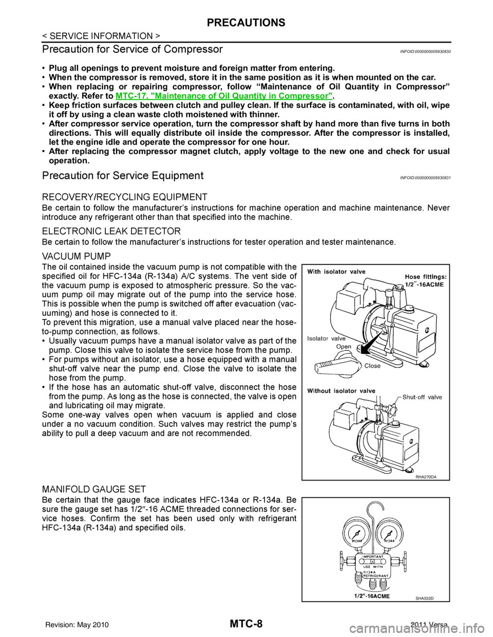
The oil contained inside the vacuum pump is not compatible with the
specified oil for HFC-134a (R-134a) A/C systems. The vent side of
the vacuum pump is exposed to atmospheric pressure. So the vac-
uum pump oil may migrate out of the pump into the service hose.
This is possible when the pump is switched off after evacuation (vac-
uuming) and hose is connected to it.
To prevent this migration, use a manual valve placed near the hose-
to-pump connection, as follows.
• Usually vacuum pumps have a manual isolator valve as part of the pump. Close this valve to isolat e the service hose from the pump.
• For pumps without an isolator, use a hose equipped with a manual shut-off valve near the pump end. Close the valve to isolate the
hose from the pump.
• If the hose has an automatic shut -off valve, disconnect the hose
from the pump. As long as the hose is connected, the valve is open
and lubricating oil may migrate.
Some one-way valves open when vacuum is applied and close
under a no vacuum condition. Such valves may restrict the pump’s
ability to pull a deep vacuum and are not recommended.
MANIFOLD GAUGE SET
Be certain that the gauge face indicates HFC-134a or R-134a. Be
sure the gauge set has 1/2 ″-16 ACME threaded connections for ser-
vice hoses. Confirm the set has been used only with refrigerant
HFC-134a (R-134a) and specified oils.
RHA270DA
SHA533D
Revision: May 2010 2011 Versa
Page 3326 of 3787

MTC-10
< SERVICE INFORMATION >
PRECAUTIONS
• Do not allow dye to come into contact with painted body panels or interior components. If dye is spilled,
clean immediately with the approved dye cleaner. Fluoresc ent dye left on a surface for an extended period of
time cannot be removed.
• Do not spray the fluorescent dye cleaning agent on hot surfaces (engine exhaust manifold, etc.).
• Do not use more than one refrigerant dye bot tle (1/4 ounce /7.4 cc) per A/C system.
• Leak detection dyes for HFC-134a (R-134a) and CFC-12 (R-12) A/C systems are different. Do not use HFC-
134a (R-134a) leak detection dye in CFC-12 (R-12) A/C s ystem or CFC-12 (R-12) leak detector dye in HFC-
134a (R-134a) A/C syst em or A/C system damage may result.
• The fluorescent properties of the dye will remain for over three (3) years unless a compressor malfunction
occurs.
IDENTIFICATION LABEL FOR VEHICLE
Vehicles with factory installed fluorescent dye have an identification label on the front underside of the hood.
NOTE:
• Vehicles with factory installed fluorescent dye have a green label.
• Vehicles without factory installed fluorescent dye have a blue label.
Revision: May 2010 2011 Versa
Page 3339 of 3787

TROUBLE DIAGNOSISMTC-23
< SERVICE INFORMATION >
C
DE
F
G H
I
K L
M A
B
MTC
N
O P
WORK SUPPORT
Display Item List
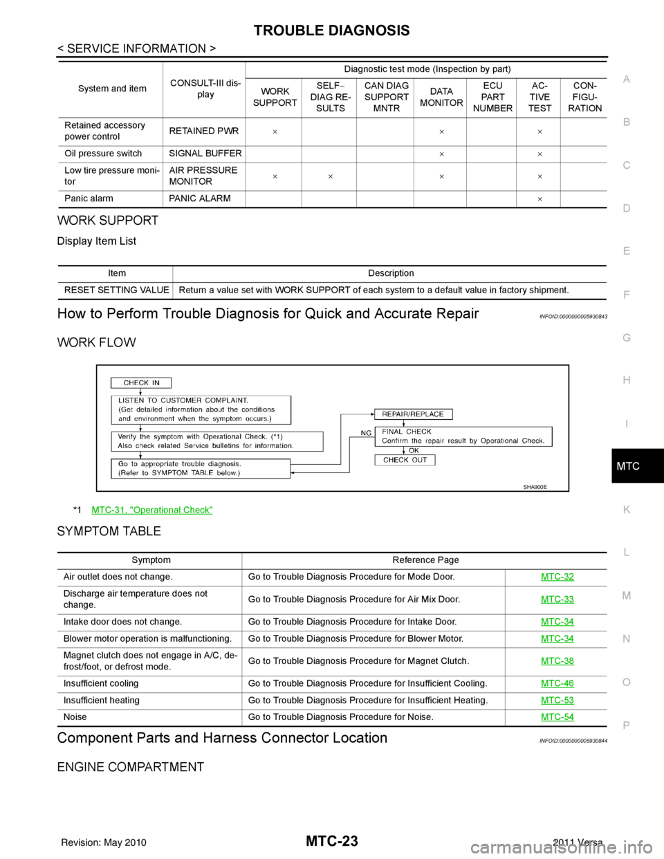
How to Perform Trouble Diagnosis for Quick and Accurate RepairINFOID:0000000005930843
WORK FLOW
SYMPTOM TABLE
Component Parts and Har ness Connector LocationINFOID:0000000005930844
ENGINE COMPARTMENT
Retained accessory
power controlRETAINED PWR
×× ×
Oil pressure switch SIGNAL BUFFER ××
Low tire pressure moni-
tor AIR PRESSURE
MONITOR
××
× ×
Panic alarm PANIC ALARM ×
System and item
CONSULT-III dis-
play Diagnostic test mode (Inspection by part)
WORK
SUPPORT SELF
−
DIAG RE-
SULTS CAN DIAG
SUPPORT
MNTR DATA
MONITOR ECU
PA R T
NUMBER AC-
TIVE
TEST CON-
FIGU-
RATION
Item Description
RESET SETTING VALUE Return a value set with WORK SUPPORT of each system to a default value in factory shipment.
*1 MTC-31, "Operational Check"
SHA900E
Symptom Reference Page
Air outlet does not change. Go to Trouble Diagnosis Procedure for Mode Door. MTC-32
Discharge air temperature does not
change.Go to Trouble Diagnosis Procedure for Air Mix Door.
MTC-33
Intake door does not change.Go to Trouble Diagnosis Procedure for Intake Door. MTC-34
Blower motor operation is malfunctioning. Go to Trouble Diagnosis Procedure for Blower Motor. MTC-34
Magnet clutch does not engage in A/C, de-
frost/foot, or defrost mode.Go to Trouble Diagnosis Procedure for Magnet Clutch.
MTC-38
Insufficient coolingGo to Trouble Diagnosis Procedure for Insufficient Cooling. MTC-46
Insufficient heatingGo to Trouble Diagnosis Procedure for Insufficient Heating. MTC-53
NoiseGo to Trouble Diagnosis Procedure for Noise. MTC-54
Revision: May 2010 2011 Versa
Page 3347 of 3787

TROUBLE DIAGNOSISMTC-31
< SERVICE INFORMATION >
C
DE
F
G H
I
K L
M A
B
MTC
N
O P
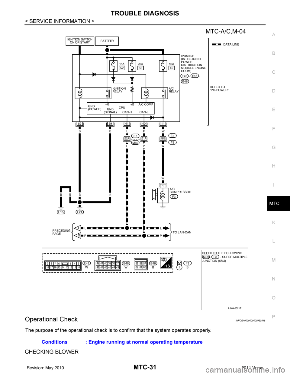
Operational CheckINFOID:0000000005930848
The purpose of the operational check is to confirm that the system operates properly.
CHECKING BLOWER
LJWA0021E
Conditions : Engine running at normal operating temperature
Revision: May 2010 2011 Versa