2011 NISSAN CUBE lights
[x] Cancel search: lightsPage 226 of 345
Black plate (224,1)
Model "Z12-D" EDITED: 2010/ 9/ 29
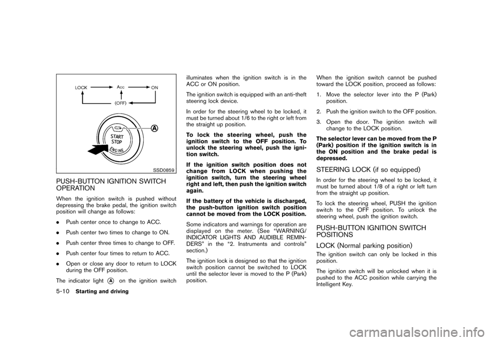
SSD0859
PUSH-BUTTON IGNITION SWITCH
OPERATIONWhen the ignition switch is pushed without
depressing the brake pedal, the ignition switch
position will change as follows:
.Push center once to change to ACC.
. Push center two times to change to ON.
. Push center three times to change to OFF.
. Push center four times to return to ACC.
. Open or close any door to return to LOCK
during the OFF position.
The indicator light
*A
on the ignition switch illuminates when the ignition switch is in the
ACC or ON position.
The ignition switch is equipped with an anti-theft
steering lock device.
In order for the steering wheel to be locked, it
must be turned about 1/6 to the right or left from
the straight up position.
To lock the steering wheel, push the
ignition switch to the OFF position. To
unlock the steering wheel, push the igni-
tion switch.
If the ignition switch position does not
change from LOCK when pushing the
ignition switch, turn the steering wheel
right and left, then push the ignition switch
again.
If the battery of the vehicle is discharged,
the push-button ignition switch position
cannot be moved from the LOCK position.
Some indicators and warnings for operation are
displayed on the meter. (See “WARNING/
INDICATOR LIGHTS AND AUDIBLE REMIN-
DERS” in the “2. Instruments and controls”
section.)
The ignition lock is designed so that the ignition
switch position cannot be switched to LOCK
until the selector lever is moved to the P (Park)
position.
When the ignition switch cannot be pushed
toward the LOCK position, proceed as follows:
1. Move the selector lever into the P (Park)
position.
2. Push the ignition switch to the OFF position.
3. Open the door. The ignition switch will change to the LOCK position.
The selector lever can be moved from the P
(Park) position if the ignition switch is in
the ON position and the brake pedal is
depressed.
STEERING LOCK (if so equipped)In order for the steering wheel to be locked, it
must be turned about 1/8 of a right or left turn
from the straight up position.
To lock the steering wheel, PUSH the ignition
switch to the OFF position. To unlock the
steering wheel, push the ignition switch.PUSH-BUTTON IGNITION SWITCH
POSITIONS
LOCK (Normal parking position)The ignition switch can only be locked in this
position.
The ignition switch will be unlocked when it is
pushed to the ACC position while carrying the
Intelligent Key.
5-10
Starting and driving
Page 228 of 345
Black plate (226,1)
Model "Z12-D" EDITED: 2010/ 9/ 27
chime sounds. The engine will start.
After step 3 is performed, when the ignition
switch is pushed without depressing the brake
pedal, the ignition switch position will change to
ACC.
NOTE:
. When the ignition switch is pushed to
the ACC or ON position or the engine is
started by the above procedures, the
Intelligent Key system warning light
may blink in yellow even if the Intelli-
gent Key is inside the vehicle. This is
not a malfunction. To stop the warning
light from blinking, touch the ignition
switch with the Intelligent Key again.
. If the Intelligent Key system warning
light in the meter is blinking in green,
replace the battery as soon as possible.
(See “KEY BATTERY REPLACEMENT”
in the “8. Maintenance and do-it-your-
self” section.) .
Make sure the area around the vehicle is
clear.
. Check fluid levels such as engine oil, cool-
ant, brake fluid, and window washer fluid as
frequently as possible, or at least whenever
you refuel.
. Check that all windows and lights are clean.
. Visually inspect tires for their appearance
and condition. Also check tires for proper
inflation.
. Lock all doors.
. Position seat and adjust head restraints.
. Adjust inside and outside mirrors.
. Fasten seat belts and ask all passengers to
do likewise.
. Check the operation of warning lights when
the ignition switch is placed in the ON
position. (See “WA RNING/INDICATOR
LIGHTS AND AUDIBLE REMINDERS” in
the “2. Instruments and controls” section.)
MODELS WITHOUT INTELLIGENT KEY
SYSTEM1. Apply the parking brake.
2. Continuously Variable Transmission
(CVT) models:
Move the selector lever to the P (Park) or N
(Neutral) position. (P is recommended.)
The starter is designed so that it does not
operate unless the selector lever is in either
of the above positions.
Manual Transmission (MT) models:
Move the shift lever to the N (Neutral)
position. Depress the clutch pedal fully to
the floor.
The starter is designed not to operate unless
the clutch pedal is fully depressed.
3. Crank the engine with your foot off the
accelerator pedal by turning the ignition
switch to START. Release the switch when
the engine starts. If the engine starts, but
fails to run, repeat the above procedure.
— If the engine is very hard to start in extremely cold weather or when restart-
ing, depress the accelerator pedal a little
(approximately 1/3 to the floor) and hold
it and then crank the engine. Release the
accelerator pedal when the engine
BEFORE STARTING THE ENGINE STARTING THE ENGINE
5-12
Starting and driving
Page 234 of 345
Black plate (232,1)
Model "Z12-D" EDITED: 2010/ 9/ 27
2. Apply the parking brake.
3. Remove the shift lock release cover
*A
using a suitable tool.
4. Push down the shift lock release using a suitable tool.
5. Push the selector lever button and move the selector lever to the N (Neutral) position
while holding down the shift lock release.
Place the ignition switch in the ON position to
unlock the steering wheel (if so equipped) . The
vehicle may be moved to the desired location.
Replace the removed shift lock release cover
after the operation.
For models with a steering wheel lock mechan-
ism: If the battery is discharged completely, the
steering wheel cannot be unlocked. Do not
move the vehicle with the steering wheel locked.
If the selector lever cannot be moved out of the
P (Park) position, have a NISSAN dealer check
the CVT system as soon as possible.
WARNING
If the selector lever cannot be moved
from the P (Park) position while the
engine is running and the brake pedal
is depressed, the stop lights may not work. Malfunctioning stop lights could
cause an accident injuring yourself and
others.
MANUAL TRANSMISSION (MT)
WARNING
.
Do not downshift abruptly on slip-
pery roads. This may cause a loss of
control.
. Do not over-rev the engine when
shifting to a lower gear. This may
cause a loss of control or engine
damage.
CAUTION
.Do not rest your foot on the clutch
pedal while driving. This may da-
mage the clutch.
. Fully depress the clutch pedal be-
fore shifting to help prevent trans-
mission damage.
. Stop your vehicle completely before
shifting into R (Reverse) .
. When the vehicle is stopped for a
period of time, for example at a stop light, shift to N (Neutral) and release
the clutch pedal with the foot brake
applied.
5-18
Starting and driving
Page 244 of 345
Black plate (242,1)
Model "Z12-D" EDITED: 2010/ 9/ 27
The Vehicle Dynamic Control (VDC) system
uses various sensors to monitor driver inputs
and vehicle motion. Under certain driving con-
ditions, the VDC system helps to perform the
following functions.
.Controls brake pressure to reduce wheel
slip on one slipping drive wheel so power is
transferred to a non slipping drive wheel on
the same axle.
. Controls brake pressure and engine output
to reduce drive wheel slip based on vehicle
speed (traction control function) .
. Controls brake pressure at individual wheels
and engine output to help the driver maintain
control of the vehicle in the following
conditions:
— understeer (vehicle tends to not follow the steered path despite increased steering
input)
— oversteer (vehicle tends to spin due to certain road or driving conditions) .
The VDC system can help the driver to maintain
control of the vehicle, but it cannot prevent loss
of vehicle control in all driving situations.
When the VDC system operates, theindicator in the instrument panel flashes so note
the following:
. The road may be slippery or the system may determine some action is required to help
keep the vehicle on the steered path.
. You may feel a pulsation in the brake pedal
and hear a noise or vibration from under the
hood. This is normal and indicates that the
VDC system is working properly.
. Adjust your speed and driving to the road
conditions.
See “Vehicle Dynamic Control (VDC) warning
light” in the “2. Instruments and controls”
section and “Vehicle Dynamic Control (VDC)
off indicator light” in the “2. Instruments and
controls” section.
If a malfunction occurs in the system, the
and
indicatorlightscomeoninthe
instrument panel. The VDC system automatically
turns off when these indicator lights are on.
The VDC OFF switch is used to turn off the VDC
system. The VDC off indicator illuminates to
indicate the VDC system is off. When the VDC
switch is used to turn off the system, the VDC
system still operates to prevent one drive wheel
from slipping by transferring power to a non
slipping drive wheel. The
indicator flashes
if this occurs. All other VDC functions are off and
the
indicator will not flash. The VDC
System is automatically reset to on when the
ignition switch is placed in the off position then
back to the on position. The computer has a built-in diagnostic feature
that tests the system each time you start the
engine and move the vehicle forward or in
reverse at a slow speed. When the self-test
occurs, you may hear a “clunk” noise and/or feel
a pulsation in the brake pedal. This is normal and
is not an indication of a malfunction.
WARNING
.
The VDC system is designed to help
the driver maintain stability but
does not prevent accidents due to
abrupt steering operation at high
speeds or by careless or dangerous
driving techniques. Reduce vehicle
speed and be especially careful
when driving and cornering on slip-
pery surfaces and always drive care-
fully.
. Do not modify the vehicle’s suspen-
sion. If suspension parts such as
shock absorbers, struts, springs,
stabilizer bars, bushings and
wheels are not NISSAN recom-
mended for your vehicle or are
extremely deteriorated the VDC sys-
tem may not operate properly. This
could adversely affect vehicle hand-
ling performance, and the
in-
VEHICLE DYNAMIC CONTROL (VDC)
SYSTEM5-28
Starting and driving
Page 245 of 345
Black plate (243,1)
Model "Z12-D" EDITED: 2010/ 9/ 27
dicator may flash or both
and
indicator lights may illuminate.
. If brake related parts such as brake
pads, rotors and calipers are not
NISSAN recommended or are extre-
mely deteriorated, the VDC system
may not operate properly and bothand
indicator lights may
illuminate.
. If engine control related parts are
not NISSAN recommended or are
extremely deteriorated, both the
and
indicator lights may
illuminate.
. When driving on extremely inclined
surfaces such as higher banked
corners, the VDC system may not
operate properly and the
in-
dicator may flash or bothand
indicator lights may illuminate.
Do not drive on these types of
roads.
. When driving on an unstable sur-
face such as a turntable, ferry,
elevator or ramp, the
indicator
may flash or bothand
indicator lights may illuminate. This
is not a malfunction. Restart the engine after driving onto a stable
surface.
. If wheels or tires other than the
NISSAN recommended ones are
used, the VDC system may not
operate properly and the
in-
dicator may flash or bothand
indicator lights may illuminate.
. The VDC system is not a substitute
for winter tires or tire chains on a
snow covered road.
FREEING A FROZEN DOOR LOCKTo prevent a door lock from freezing, apply
deicer through the key hole. If the lock becomes
frozen, heat the key before inserting it into the
key hole or use the remote keyless entry keyfob.ANTI-FREEZEIn the winter when it is anticipated that the
outside temperature will drop below 32 8F(0 8C) ,
check the anti-freeze to assure proper winter
protection. For additional information, see “EN-
GINE COOLING SYSTEM” in the “8. Main-
tenance and do-it-yourself” section.BATTERYIf the battery is not fully charged during
extremely cold weather conditions, the battery
fluid may freeze and damage the battery. To
maintain maximum efficiency, the battery should
be checked regularly. For additional information,
see “BATTERY” in the “8. Maintenance and do-
it-yourself” section.DRAINING OF COOLANT WATERIf the vehicle is to be left outside without anti-
freeze, drain the cooling system, including the
engine block. Refill before operating the vehicle.
For details, see “ENGINE COOLING SYSTEM”
in the “8. Maintenance and do-it-yourself”
section.COLD WEATHER DRIVING
Starting and driving
5-29
Page 250 of 345
Black plate (248,1)
Model "Z12-D" EDITED: 2010/ 9/ 27
To shut off the engine in an emergency situation
while driving perform the following procedure:
.Rapidly push the push-button ignition switch
3 consecutive times, or
. Push and hold the push-button ignition
switch for more than 2 seconds.
TIRE PRESSURE MONITORING SYS-
TEM (TPMS)This vehicle is equipped with the Tire Pressure
Monitoring System (TPMS) . It monitors tire
pressure of all tires except the spare. When
the low tire pressure warning light is lit, one or
more of your tires is significantly under-inflated.
If the vehicle is being driven with low tire
pressure, the TPMS will activate and warn you
of it by the low tire pressure warning light. This
system will activate only when the vehicle is
driven at speeds above 16 MPH (25 km/h) . For
more details, see “WARNING/INDICATOR
LIGHTS AND AUDIBLE REMINDERS” in the
“2. Instruments and controls” section and “TIRE
PRESSURE MONITORING SYSTEM (TPMS)”
in the “5. Starting and driving” section.
WARNING
.If the low tire pressure warning light
illuminates while driving, avoid sud-
den steering maneuvers or abrupt
braking, reduce vehicle speed, pull
off the road to a safe location and
stop the vehicle as soon as possi-
ble. Driving with under-inflated tires
may permanently damage the tires
and increase the likelihood of tire
failure. Serious vehicle damage could occur and may lead to an
accident and could result in serious
personal injury. Check the tire pres-
sure for all four tires. Adjust the tire
pressure to the recommended COLD
tire pressure shown on the Tire and
Loading Information label to turn
the low tire pressure warning light
OFF. If you have a flat tire, replace it
with a spare tire as soon as possi-
ble.
. When a spare tire is mounted or a
wheel is replaced, the TPMS will not
function and the low tire pressure
warning light will flash for approxi-
mately 1 minute. The light will
remain on after 1 minute. Contact
your NISSAN dealer as soon as
possible for tire replacement and/
or system resetting.
. Replacing tires with those not ori-
ginally specified by NISSAN could
affect the proper operation of the
TPMS.
. Do not inject any tire liquid or
aerosol tire sealant into the tires,
as this may cause a malfunction of
the tire pressure sensors.
EMERGENCY ENGINE SHUT OFF
(models with Intelligent Key system) FLAT TIRE6-2
In case of emergency
Page 258 of 345
Black plate (256,1)
Model "Z12-D" EDITED: 2010/ 9/ 27
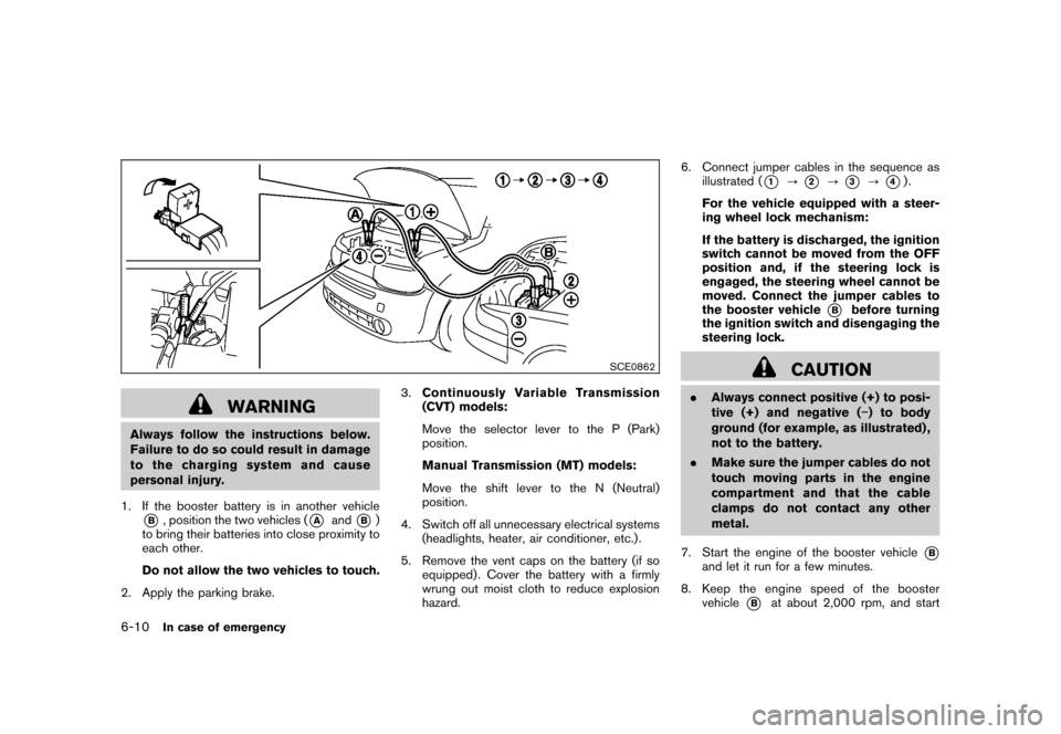
SCE0862
WARNING
Always follow the instructions below.
Failure to do so could result in damage
to the charging system and cause
personal injury.
1. If the booster battery is in another vehicle*B, position the two vehicles (
*A
and
*B)
to bring their batteries into close proximity to
each other.
Do not allow the two vehicles to touch.
2. Apply the parking brake. 3.
Continuously Variable Transmission
(CVT) models:
Move the selector lever to the P (Park)
position.
Manual Transmission (MT) models:
Move the shift lever to the N (Neutral)
position.
4. Switch off all unnecessary electrical systems (headlights, heater, air conditioner, etc.) .
5. Remove the vent caps on the battery (if so equipped) . Cover the battery with a firmly
wrung out moist cloth to reduce explosion
hazard. 6. Connect jumper cables in the sequence as
illustrated (
*1
?
*2
?
*3
?
*4).
For the vehicle equipped with a steer-
ing wheel lock mechanism:
If the battery is discharged, the ignition
switch cannot be moved from the OFF
position and, if the steering lock is
engaged, the steering wheel cannot be
moved. Connect the jumper cables to
the booster vehicle
*B
before turning
the ignition switch and disengaging the
steering lock.
CAUTION
. Always connect positive (+) to posi-
tive (+) and negative ( �) to body
ground (for example, as illustrated) ,
not to the battery.
. Make sure the jumper cables do not
touch moving parts in the engine
compartment and that the cable
clamps do not contact any other
metal.
7. Start the engine of the booster vehicle
*B
and let it run for a few minutes.
8. Keep the engine speed of the booster vehicle
*B
at about 2,000 rpm, and start
6-10
In case of emergency
Page 275 of 345
Black plate (25,1)
8 Maintenance and do-it-yourself
Model "Z12-D" EDITED: 2010/ 9/ 27
Maintenance requirement..................................... 8-2
Scheduled maintenance ................................... 8-2
General maintenance ...................................... 8-2
Where to go for service ................................... 8-2
General maintenance .......................................... 8-2
Explanation of maintenance items ....................... 8-2
Maintenance precautions ..................................... 8-5
Engine compartment check locations ...................... 8-6
MR18DE engine ............................................ 8-6
Engine cooling system ......................................... 8-7
Checking engine coolant level ........................... 8-8
Changing engine coolant ................................. 8-8
Engine oil ......................................................... 8-9
Checking engine oil level ................................. 8-9
Changing engine oil and filter ............................ 8-9
Continuously Variable Transmission (CVT) fluid ........ 8-11
Brake and clutch fluid ....................................... 8-11
Window washer fluid ........................................ 8-12
Battery .......................................................... 8-13
Jump starting .............................................. 8-14
Variable voltage control system (if so equipped) ...... 8-15
Drive belt ....................................................... 8-15
Spark plugs .................................................... 8-16
Replacing spark plugs ................................... 8-16 Air cleaner
...................................................... 8-16
Windshield wiper blades .................................... 8-17
Cleaning .................................................... 8-17
Replacing ................................................... 8-18
Rear window wiper blade ................................... 8-19
Brakes ........................................................... 8-19
Self-adjusting brakes .................................... 8-19
Brake pad wear warning ................................ 8-19
Fuses ............................................................ 8-20
Engine compartment ..................................... 8-20
Passenger compartment ................................ 8-21
Key battery replacement .................................... 8-23
Keyfob ....................................................... 8-23
Intelligent Key .............................................. 8-24
Lights ............................................................ 8-26
Headlights .................................................. 8-27
Exterior and interior lights ............................... 8-28
Wheels and tires .............................................. 8-30
Tire pressure ............................................... 8-30
Tire labeling ................................................ 8-32
Types of tires .............................................. 8-34
Tire chains .................................................. 8-35
Changing wheels and tires ............................. 8-36