2011 NISSAN CUBE display
[x] Cancel search: displayPage 91 of 345
Black plate (89,1)
Model "Z12-D" EDITED: 2010/ 9/ 27
— An emission control system and/or CVT
malfunction has been detected. Check the
fuel-filler cap. If the LOOSE FUEL CAP
warning message is displayed on the twin
trip odometer, if the fuel-filler cap is loose or
missing, tighten or install the cap and
continue to drive the vehicle. The
light
should turn off after a few driving trips. If the
light does not turn off after a few
driving trips, have the vehicle inspected by a
NISSAN dealer. You do not need to have
your vehicle towed to the dealer.
. Malfunction indicator light blinking — An
engine misfire has been detected which may
damage the emission control system.
To reduce or avoid emission control system
damage:
a) Do not drive at speeds above 45 MPH (72 km/h) .
b) Avoid hard acceleration or deceleration.
c) Avoid steep uphill grades.
d) If possible, reduce the amount of cargo being hauled or towed.
The malfunction indicator light may stop
blinking and remain illuminated.
Have the vehicle inspected by a NISSAN
dealer. You do not need to have your vehicle towed to the dealer.
CAUTION
Continued vehicle operation without
having the emission control system
and/or CVT system checked and re-
paired as necessary could lead to poor
driveability, reduced fuel economy, and
possible damage to the emission con-
trol system.
Overdrive off indicator light (if so
equipped)
The overdrive off indicator light illuminates when
the overdrive off mode is selected.
For additional information, see ““CONTINU-
OUSLY VARIABLE TRANSMISSION (CVT)” in
the “5. Starting and driving” section of this
manual.
Security indicator light
The light blinks when the ignition switch is in the
ACC, OFF or LOCK position. This function
indicates the security system equipped on the
vehicle is operational.
If the security system is malfunctioning, this lightwill remain on while the ignition switch is in the
ON position. For additional information, see
“SECURITY SYSTEMS” later in this section.
Vehicle Dynamic Control (VDC)
warning light
The light will blink when the Vehicle Dynamic
Control (VDC) system is operating, thus alerting
the driver that the vehicle is nearing its traction
limits. The road surface may be slippery.
Low beam indicator light
The light illuminates when the headlight switch is
turned to the
position.
Turn signal/hazard indicator lights
The light flashes when the turn signal switch
lever or hazard switch is turned on.
Vehicle Dynamic Control (VDC) off
indicator light
The light illuminates when the Vehicle Dynamic
Control (VDC) off switch is pushed to OFF. This
indicates that the VDC system is not operating.
When the VDC off indicator light and slip
indicator light illuminate with the VDC system
turned on, this light alerts the driver to the fact
Instruments and controls
2-17
Page 101 of 345
Black plate (99,1)
Model "Z12-D" EDITED: 2010/ 9/ 27
SIC4128SIC4129
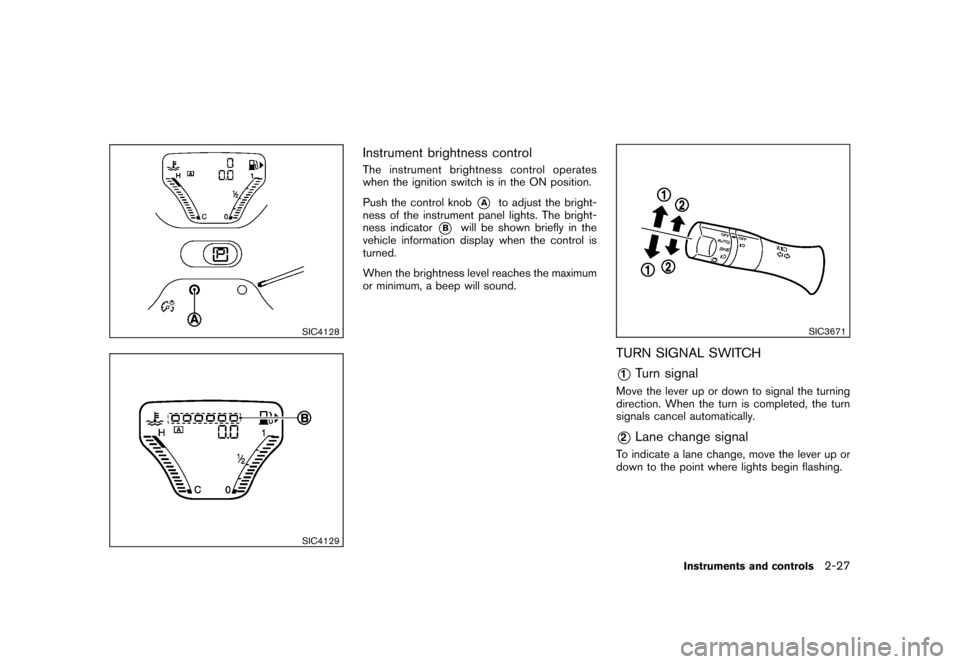
Instrument brightness controlThe instrument brightness control operates
when the ignition switch is in the ON position.
Push the control knob
*A
to adjust the bright-
ness of the instrument panel lights. The bright-
ness indicator
*B
will be shown briefly in the
vehicle information display when the control is
turned.
When the brightness level reaches the maximum
or minimum, a beep will sound.
SIC3671
TURN SIGNAL SWITCH*1
Turn signal
Move the lever up or down to signal the turning
direction. When the turn is completed, the turn
signals cancel automatically.*2
Lane change signal
To indicate a lane change, move the lever up or
down to the point where lights begin flashing.
Instruments and controls
2-27
Page 105 of 345
Black plate (103,1)
Model "Z12-D" EDITED: 2010/ 9/ 27
The digital clock (in the audio unit) displays time
when the ignition switch is in the ACC or ON
position.
The clock ON or OFF mode can be selected.
If the power supply is disconnected, the
clock will not indicate the correct time.
Readjust the time.
SIC4131
Type A
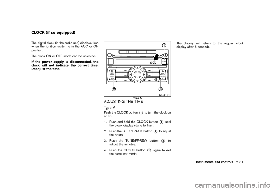
ADJUSTING THE TIME
Type APush the CLOCK button
*1
to turn the clock on
or off.
1. Push and hold the CLOCK button
*1
until
the clock display starts to flash.
2. Push the SEEK/TRACK button
*2
to adjust
the hours.
3. Push the TUNE/ FF·REW button*3
to
adjust the minutes.
4. Push the CLOCK button
*1
again to exit
the clock set mode. The display will return to the regular clock
display after 5 seconds.
CLOCK (if so equipped)
Instruments and controls
2-31
Page 106 of 345
Black plate (104,1)
Model "Z12-D" EDITED: 2010/ 9/ 27
SIC4146
Type B
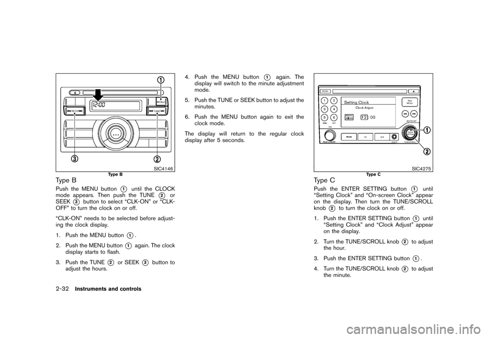
Type BPush the MENU button
*1
until the CLOCK
mode appears. Then push the TUNE
*2
or
SEEK
*3
button to select “CLK-ON” or “CLK-
OFF” to turn the clock on or off.
“CLK-ON” needs to be selected before adjust-
ing the clock display.
1. Push the MENU button
*1.
2. Push the MENU button
*1
again. The clock
display starts to flash.
3. Push the TUNE
*2
or SEEK
*3
button to
adjust the hours. 4. Push the MENU button
*1
again. The
display will switch to the minute adjustment
mode.
5. Push the TUNE or SEEK button to adjust the minutes.
6. Push the MENU button again to exit the clock mode.
The display will return to the regular clock
display after 5 seconds.
SIC4275
Type C
Type CPush the ENTER SETTING button
*1
until
“Setting Clock” and “On-screen Clock” appear
on the display. Then turn the TUNE/SCROLL
knob
*2
to turn the clock on or off.
1. Push the ENTER SETTING button
*1
until
“Setting Clock” and “Clock Adjust” appear
on the display.
2. Turn the TUNE/SCROLL knob
*2
to adjust
the hour.
3. Push the ENTER SETTING button*1.
4. Turn the TUNE/SCROLL knob
*2
to adjust
the minute.
2-32
Instruments and controls
Page 107 of 345
Black plate (105,1)
Model "Z12-D" EDITED: 2010/ 9/ 27
5. Push the ENTER SETTING button
*1.
The display will return to the regular clock
display after 5 seconds.
RESETTING THE TIME (Type B)By holding down the MENU button and then
pushing the TUNE or SEEK button, the time will
be reset as follows.
. In case the displayed minute is in the range
of 00 - 29, the hour will stay the same and
the minute will be reset to 00.
. In case the displayed minute is in the range
of 30 - 59, the hour will be advanced by one
hour and the minute will be reset to 00.
For example, if the MENU and TUNE buttons are
pushed while the time is between “8:00” and
“8:29”, the display will be reset to “8:00”. If
pushed while the time is between “8:30” and
“8:59”, the display will be reset to “9:00”. At the
same time the display will return to the previous
audio mode.
SIC4132
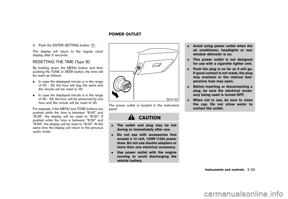
The power outlet is located in the instrument
panel.
CAUTION
. The outlet and plug may be hot
during or immediately after use.
. Do not use with accessories that
exceed a 12 volt, 120W (10A) power
draw. Do not use double adapters or
more than one electrical accessory.
. Use power outlet with the engine
running to avoid discharging the
vehicle battery. .
Avoid using power outlet when the
air conditioner, headlights or rear
window defroster is on.
. This power outlet is not designed
for use with a cigarette lighter unit.
. Push the plug in as far as it will go.
If good contact is not made, the plug
may overheat or the internal tem-
perature fuse may open.
. Before inserting or disconnecting a
plug, be sure the electrical acces-
sory being used is turned OFF.
. When not in use, be sure to close
the cap. Do not allow water to
contact the outlet.POWER OUTLET
Instruments and controls
2-33
Page 143 of 345
Black plate (141,1)
Model "Z12-D" EDITED: 2010/ 9/ 27
.Do not fill a portable fuel container
in the vehicle or trailer. Static elec-
tricity can cause an explosion of
flammable liquid, vapor or gas in
any vehicle or trailer. To reduce the
risk of serious injury or death when
filling portable fuel containers:
— Always place the container on
the ground when filling.
— Do not use electronic devices when filling.
— Keep the pump nozzle in contact with the container while you are
filling it.
— Use only approved portable fuel containers for flammable liquid.
CAUTION
. If fuel is spilled on the vehicle body,
flush it away with water to avoid
paint damage.
. Insert the cap straight into the fuel-
filler tube, then tighten until the
fuel-filler cap clicks. Failure to tight-
en the fuel-filler cap properly may
cause the
malfunction indicator
light (MIL) to illuminate. If the
light illuminates because the fuel-
filler cap is loose or missing, tighten
or install the cap and continue to
drive the vehicle. The
light
should turn off after a few driving
trips. If the
light does not turn
off after a few driving trips, have the
vehicle inspected by a NISSAN deal-
er.
For additional information, see
“Malfunction Indicator Light (MIL)”
in the “2. Instruments and controls”
section.
. The LOOSE FUEL CAP warning
message will be displayed if the
fuel-filler cap is not properly tigh-
tened. Failure to tighten the fuel-
filler cap properly after the LOOSE
FUEL CAP warning message is dis-
played may cause the
Malfunc-
tion Indicator Light (MIL) to
illuminate.
SIC4712
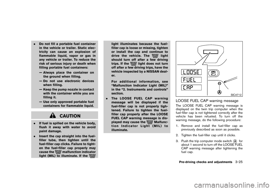
LOOSE FUEL CAP warning messageThe LOOSE FUEL CAP warning message is
displayed on the twin trip computer when the
fuel-filler cap is not tightened correctly after the
vehicle has been refueled. To turn off the
warning message, do the following procedure:
1. Remove and install the fuel-filler cap as previously described as soon as possible.
2. Tighten the fuel-filler cap until it clicks.
3. Push the trip computer mode switch
*A
for
about 1 second to turn off the LOOSE FUEL
CAP warning message after tightening the
fuel cap.
Pre-driving checks and adjustments
3-25
Page 149 of 345
Black plate (13,1)
4 Heater, air conditioner, audio and phonesystems
Model "Z12-D" EDITED: 2010/ 9/ 27
Safety note ....................................................... 4-2
Control panel buttons — color screen with
navigation system (if so equipped) ......................... 4-2
How to use touch screen ................................. 4-3
How to use the BACK button ........................... 4-5
How to use brightness control and display ON/
OFF button ................................................... 4-5
How to use the setup button ............................ 4-5
RearView monitor (if so equipped) ......................... 4-9
How to read the displayed lines ......................... 4-9
Difference between predicted and actual
distances ................................................... 4-10
How to adjust the screen ............................... 4-12
Operating tips ............................................. 4-12
Ventilators ...................................................... 4-13
Center ventilators ......................................... 4-13
Side ventilators ............................................ 4-13
Heater and air conditioner .................................. 4-13
Manual air conditioner ................................... 4-14
Automatic air conditioner (if so equipped) .......... 4-17
Operating tips ............................................. 4-19
In-cabin microfilter ........................................ 4-19
Servicing air conditioner ................................ 4-20 Audio system
.................................................. 4-20
Audio operation precautions ........................... 4-20
FM-AM radio with Compact Disc (CD) player
(Type A)..................................................... 4-34
FM-AM radio with Compact Disc (CD) player
(Type B)..................................................... 4-38
FM-AM-SAT radio with Compact Disc (CD)
player (Type C) ............................................ 4-45
CD care and cleaning ................................... 4-52
Steering wheel switch for audio control
(if so equipped) ........................................... 4-53
Antenna ..................................................... 4-54
Car phone or CB radio ...................................... 4-54
Bluetooth
®Hands-Free Phone System
(if so equipped) ............................................... 4-55
Regulatory information ................................... 4-57
Using the system ......................................... 4-57
Control buttons ........................................... 4-59
Getting started ............................................ 4-60
List of voice commands ................................. 4-61
Speaker Adaptation (SA) mode ....................... 4-65
Troubleshooting guide ................................... 4-67
Page 150 of 345
Black plate (148,1)
Model "Z12-D" EDITED: 2010/ 9/ 27
WARNING
.Do not disassemble or modify this
system. If you do, it may result in
accidents, fire, or electric shock.
. In case you notice any foreign
object in the system hardware, spill
liquid on it, or notice smoke or smell
coming from it, stop using the
system immediately and contact
your nearest NISSAN dealer. Ignor-
ing such conditions may lead to
accidents, fire, or electric shock.
CAUTION
Do not use this system if you notice any
abnormality, such as a frozen screen or
lack of sound. Continued use of the
system may result in an accident, fire or
electric shock.
Do not attempt to operate the system in
extreme temperature conditions [below
� 48F( �208 C) and above 158 8F(70 8C)].
Operating this system under these condi-
tions may result in system malfunctions.
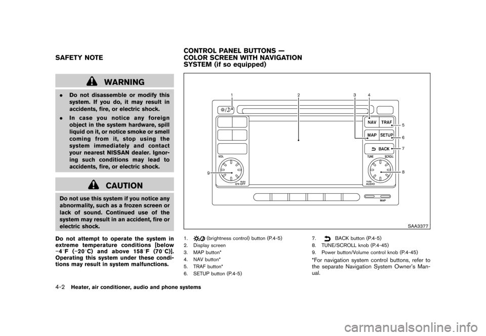
SAA3377
1.
(brightness control) button (P.4-5)
2. Display screen
3. MAP button*
4. NAV button*
5. TRAF button*
6. SETUP button (P.4-5) 7.
BACK button (P.4-5)
8. TUNE/SCROLL knob (P.4-45)
9. Power button/Volume control knob (P.4-45)
*For navigation system control buttons, refer to
the separate Navigation System Owner’s Man-
ual.
SAFETY NOTE CONTROL PANEL BUTTONS —
COLOR SCREEN WITH NAVIGATION
SYSTEM (if so equipped)4-2
Heater, air conditioner, audio and phone systems