Page 407 of 489
CHANGING ENGINE OIL
1. Park the vehicle on a level surface and applythe parking brake.
2. Start the engine and let it idle until it reaches operating temperature, then turn it off.
3. Remove the oil filler cap
�Aby turning it
counterclockwise.
4. Place a large drain pan under the drain plug
�B.
5. Remove the drain plug
�Bwith a wrench by
turning it counterclockwise and completely
drain the oil. If the oil filter is to be changed, remove and
replace it at this time. See “Changing engine
oil filter” in this section.
● Waste oil must be disposed of prop-
erly.
● Check your local regulations.
Page 408 of 489
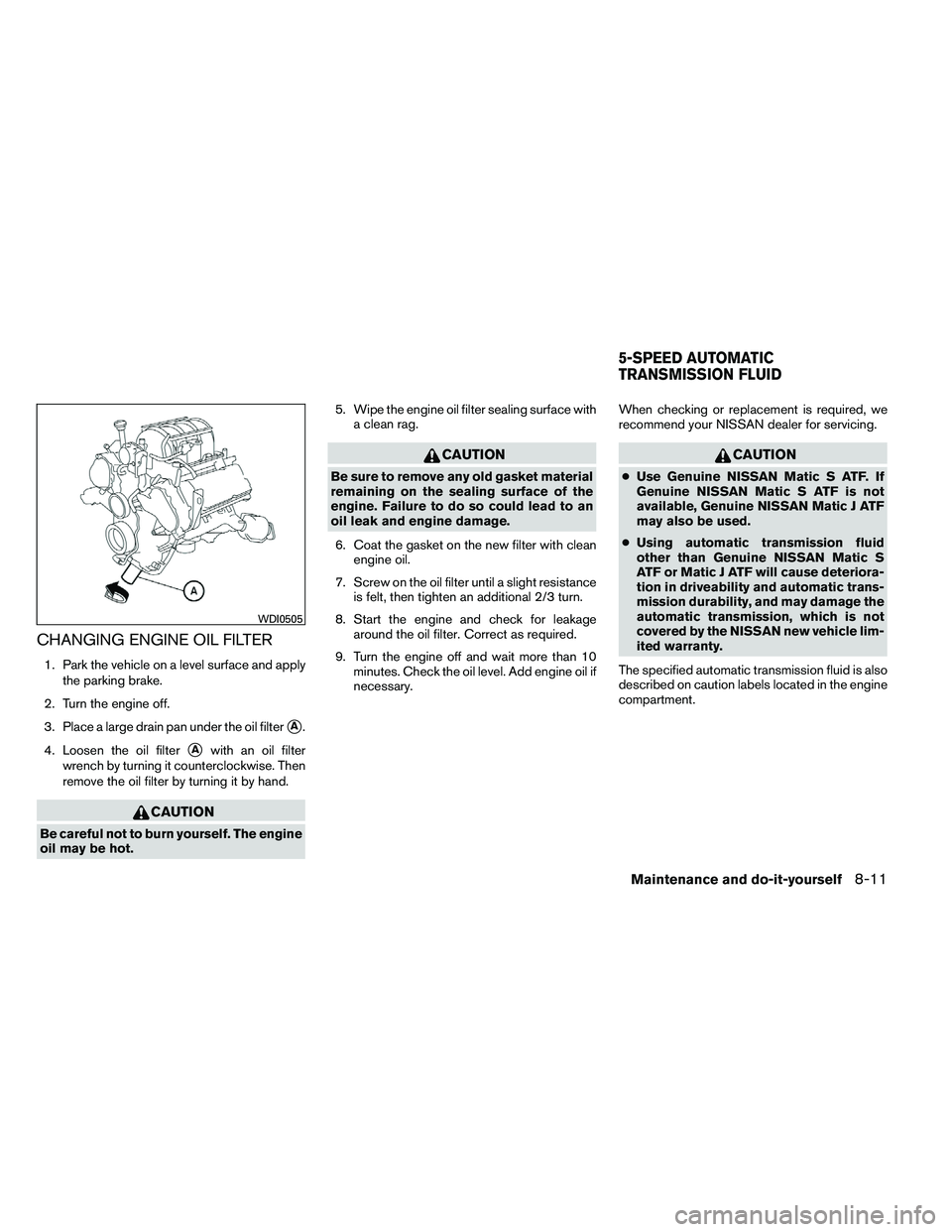
CHANGING ENGINE OIL FILTER
1. Park the vehicle on a level surface and applythe parking brake.
2. Turn the engine off.
3. Place a large drain pan under the oil filter
�A.
4. Loosen the oil filter
�Awith an oil filter
wrench by turning it counterclockwise. Then
remove the oil filter by turning it by hand.
Page 410 of 489

BRAKE FLUID
Check the brake fluid level in the reservoir. If the
fluid level is below the MIN line or the brake
warning light comes on, add Genuine NISSAN
Super Heavy Duty Brake Fluid or equivalentDOT
3 fluid up to the MAX line. If fluid must be added
frequently, the system should be checked by a
NISSAN dealer.
WINDSHIELD-WASHER FLUID
RESERVOIR
Fill the windshield-washer fluid reservoir periodi-
cally. Add windshield-washer fluid when the low
windshield-washer fluid warning light comes on.
To fill the windshield-washer fluid reservoir, lift
the cap off the reservoir and pour the windshield-
washer fluid into the reservoir opening.
Add a washer solvent to the washer for better
cleaning. In the winter season, add a windshield
washer antifreeze. Follow the manufacturer’s in-
structions for the mixture ratio. Refill the reservoir more frequently when driving
conditions require an increased amount of
windshield-washer fluid.
Recommended fluid is Genuine NISSAN Wind-
shield Washer Concentrate Cleaner & Anti-
freeze or equivalent.
Page 420 of 489
If the brakes do not operate properly, have the
brakes checked by a NISSAN dealer.
Self-adjusting brakes
Your vehicle is equipped with self-adjusting
brakes.
The front and rear disc-type brakes self-adjust
every time the brake pedal is applied.
Page 467 of 489
NOTE:
A weight-distributing hitch system may af-
fect the operation of trailer surge brakes. If
you are considering use of a weight-
distributing hitch system with a surge
brake-equipped trailer, check with the
surge brake, hitch or trailer manufacturer
to determine if and how this can be done.
Follow the instructions provided by the manufac-
turer for installing and using the weight-
distributing hitch system.
General set-up instructions are as follows:1. Park unloaded vehicle on a level surface. With the ignition on and the doors closed,
allow the vehicle to stand for several minutes
so that it can level.
2. Measure the height of a reference point on the front and rear bumpers at the center of
the vehicle.
3. Attach the trailer to the vehicle and adjust the hitch equalizers so that the front bumper
height is within0-.5inches (0 – 13 mm) of
the reference height measured in step 2. The
rear bumper should be no higher than the
reference height measured in step 2.
Page 468 of 489
 . Suitable genu-
ine NISSAN hitches, ball mounts and
hitch balls for pickup trucks and s")
CAUTION
●Special hitches which include frame re-
inforcements are required for towing
above 2,000 lb (907 kg) . Suitable genu-
ine NISSAN hitches, ball mounts and
hitch balls for pickup trucks and sport
utility vehicles are available at a
NISSAN dealer.
● The hitch should not be attached to or
affect the operation of the impact-
absorbing bumper.
● Do not use axle-mounted hitches.
● Do not modify the vehicle exhaust sys-
tem, brake system, etc. to install a
trailer hitch.
● To reduce the possibility of additional
damage if your vehicle is struck from
the rear, where practical, remove the
receiver when not in use.
● Regularly check that all trailer hitch
mounting bolts are securely mounted.
Tire pressures
● When towing a trailer, inflate the ve-
hicle tires to the recommended cold
tire pressure indicated on the tire
placard.
● Trailer tire condition, size, load rating
and proper inflation pressure should
be in accordance with the trailer and
tire manufacturer’s specifications.
Safety chains
Always use suitable safety chains between your
vehicle and the trailer. The safety chains should
be crossed and should be attached to the hitch,
not to the vehicle bumper or axle. The safety
chains can be attached to the bumper if the hitch
ball is mounted to the bumper. Be sure to leave
enough slack in the chains to permit turning
corners.
Trailer lights
Page 469 of 489
 or more, trailers with a brake
system MUST be used.However, most states
require a separate braking system on trailers with
a loaded w")
Trailer brakes
When towing a trailer load of 3,500 lbs.
(1,587 kg) or more, trailers with a brake
system MUST be used.However, most states
require a separate braking system on trailers with
a loaded weight above a specific amount. Make
sure the trailer meets the local regulations and
the regulations where you plan to tow.
Several types of braking systems are available.
Surge Brakes - The surge brake actuator is
mounted on the trailer tongue with a hydraulic line
running to each trailer wheel. Surge brakes are
activated by the trailer pushing against the hitch
ball when the tow vehicle is braking. Hydraulic
surge brakes are common on rental trailers and
some boat trailers. In this type of system, there is
no hydraulic or electric connection for brake op-
eration between the tow vehicle and the trailer.
Electric Trailer Brakes - Electric braking sys-
tems are activated by an electronic signal sent
from a trailer brake controller (special brake-
sensing module) . If electric trailer brakes are
used, see “Electric trailer brake controller” in this
section.
Have a professional supplier of towing equip-
ment make sure the trailer brakes are properly
installed and demonstrate proper brake function
testing.
Page 470 of 489
To install the electric trailer brake controller
jumper harness, perform the following proce-
dure:1. Open the driver door. Move the seat to the rearmost position.
2. Apply the parking brake to access thejumper harness connector. 3. Locate the jumper harness connector under
the lower portion of the instrument panel.
The connector is taped to the wiring harness
�1as indicated.
● The connector is marked with a white tag
with “elec brake conn”.