Page 12 of 489
1. Engine hood (P. 3-23)
2. Windshield wiper and washer switch(P. 2-28)
3. Windshield (P. 8-20)
4. Power windows (P. 2-51)
5. Door locks, NISSAN Intelligent Key™,
keys (P. 3-5, 3-12, 3-2)
6. Mirrors (P. 3-32)
7. Tire pressure (P. 9-13)
8. Flat tire (P. 6-2)
9. Tire chains (P. 8-43)
10. Replacing bulbs (P. 8-33)
11. Headlight and turn signal switch
(P. 2-30)
12. Fog light switch (P. 2-34)
13. Tow hooks (if so equipped) (P. 6-13)
See the page number indicated in paren-
theses for operating details.
Page 93 of 489

2 Instruments and controls
Instrument panel...................................2-2
Meters and gauges ................................2-4
Speedometer and odometer . . ...................2-5
Tachometer ....................................2-6
Engine coolant temperature gauge ...............2-6
Fuel gauge ....................................2-7
Engine oil pressure gauge .......................2-7
Voltmeter ......................................2-8
Automatic transmission fluid temperature
gauge .........................................2-8
Compass display (if so equipped) ...................2-9
Compass display .............................. 2-10
Warning/indicator lights and audible reminders ......2-13
Checking bulbs ............................... 2-13
Warning lights ................................ 2-14
Indicator lights ................................ 2-19
Audible reminders ............................. 2-20
Vehicle Information Display ........................2-21
How to use the Vehicle Information Display .......2-21
Security systems ................................. 2-26
Vehicle security system ......................... 2-26
NISSAN vehicle immobilizer system .............2-27
Windshield wiper and washer switch ...............2-28Switch operation
.............................. 2-28
Rear window wiper and washer switch ..............2-29
Rear window and outside mirror defroster switch .....2-30
Headlight and turn signal switch ....................2-30
Headlight control switch ........................ 2-30
Daytime running light system (Canada only) ......2-32
Instrument brightness control ...................2-33
Turn signal switch ............................. 2-33
Fog light switch (if so equipped) ................2-34
Hazard warning flasher switch .....................2-34
Horn ............................................ 2-35
Heated seat (if so equipped) .......................2-35
Heated steering wheel (if so equipped) .............2-36
Vehicle Dynamic Control (VDC) off switch ...........2-37
Rear sonar system off switch (if so equipped) ........2-37
Front
and rear sonar system off switch
(if so equipped) .................................. 2-38
Tow mode switch ................................. 2-38
Power outlet ..................................... 2-39
Storage ......................................... 2-40
Instrument panel storage trays ..................2-40
Console box .................................. 2-41
Glove box .................................... 2-42
Page 123 of 489
To defrost the rear window glass and outside
mirrors:
Start the engine and push the rear window de-
froster switch. The rear window defroster indica-
tor light on the display screen comes on. Push the
switch again to turn the defroster off.
The rear window defroster automatically turns off
after approximately 15 minutes.
Page 187 of 489
VANITY MIRRORS
To access the vanity mirror, pull the sun visor
down and flip open the mirror cover. The vanity
mirror will illuminate when the mirror cover is
open.
REARVIEW MIRROR (if so equipped)
The night position�1reduces glare from the
headlights of vehicles behind you at night.
Use the day position
�2when driving in daylight
hours.
Page 189 of 489
To turn on the automatic anti-glare feature again,
press:● the | button for inside mirrors without
compass.
● the
Page 190 of 489
WARNING
●Objects viewed in the outside mirror on
the passenger side are closer than they
appear. Be careful when moving to the
right. Using only this mirror could cause
an accident. Use the inside mirror or
glance over your shoulder to properly
judge distances to other objects.
● Do not adjust the mirrors while driving.
You could lose control of your vehicle
and cause an accident.
Manual folding outside mirrors (if so
equipped)
Pull the outside mirror toward the door to fold it.
Power folding outside mirrors (if so
equipped)
Page 191 of 489
If one of the mirrors are manually operated or
bumped, the mirror body can become loose at
the pivot point. To correct electronic mirror op-
eration, cycle the mirrors by pushing the
“CLOSE” switch until completely closed, then
push the “OPEN” switch until the mirrors are in
the open position.
Automatic anti-glare outside mirrors (if
so equipped)
The outside mirrors will automatically dim during
nighttime conditions to reduce the glare from the
headlights of trailing vehicles. The automatic anti-
glare feature operates only when the ignition
switch is placed in the ON position.
The automatic anti-glare feature will be on when
starting the vehicle. The indicator light on the
automatic anti-glare rearview mirror will illuminate
when the automatic anti-glare feature is operat-
ing.
To turn off the anti-glare feature, press the
Page 192 of 489

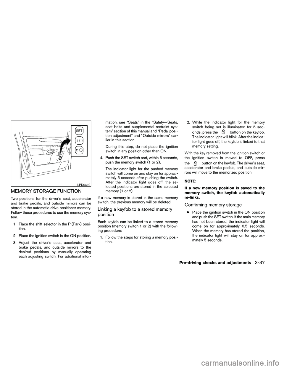
MEMORY STORAGE FUNCTION
Two positions for the driver’s seat, accelerator
and brake pedals, and outside mirrors can be
stored in the automatic drive positioner memory.
Follow these procedures to use the memory sys-
tem.1. Place the shift selector in the P (Park) posi- tion.
2. Place the ignition switch in the ON position.
3. Adjust the driver’s seat, accelerator and brake pedals, and outside mirrors to the
desired positions by manually operating
each adjusting switch. For additional infor- mation, see “Seats” in the “Safety—Seats,
seat belts and supplemental restraint sys-
tem” section of this manual and “Pedal posi-
tion adjustment” and “Outside mirrors” ear-
lier in this section.
During this step, do not place the ignition
switch in any position other than ON.
4. Push the SET switch and, within 5 seconds, push the memory switch (1 or 2) .
The indicator light for the pushed memory
switch will come on and stay on for approxi-
mately 5 seconds after pushing the switch.
After the indicator light goes off, the se-
lected positions are stored in the selected
memory (1 or 2) .
If a new memory is stored in the same memory
switch, the previous memory will be deleted.
Linking a keyfob to a stored memory
position
Each keyfob can be linked to a stored memory
position (memory switch 1 or 2) with the follow-
ing procedure: 1. Follow the steps for storing a memory posi- tion. 2. While the indicator light for the memory
switch being set is illuminated for 5 sec-
onds, press the