2011 NISSAN 370Z COUPE steering wheel
[x] Cancel search: steering wheelPage 309 of 419
Black plate (305,1)
Model "Z34-D" EDITED: 2010/ 7/ 27
distances may also be longer on
rough, gravel or snow covered
roads, or if you are using tire chains.
Alwaysmaintainasafedistance
from the vehicle in front of you.
Ultimately, the driver is responsible
for safety.
. Tire type and condition may also
affect braking effectiveness.
— When replacing tires, install the
specified size of tires on all four
wheels.
— When installing a spare tire, make sure that it is the proper
size and type as specified on the
Tire and Loading Information
label. See “TIRE AND LOADING
INFORMATION LABEL” in the “9.
Technical and consumer infor-
mation” section of this manual.
— For detailed information, see “WHEELS AND TIRES” in the
“8. Maintenance and do-it-your-
self” section of this manual.
The Anti-lock Braking System (ABS) controls
the brakes so the wheels do not lock during hard
braking or when braking on slippery surfaces.
The system detects the rotation speed at each wheel and varies the brake fluid pressure to
prevent each wheel from locking and sliding. By
preventing each wheel from locking, the system
helps the driver maintain steering control and
helps to minimize swerving and spinning on
slippery surfaces.
Using the systemDepress the brake pedal and hold it down.
Depress the brake pedal with firm steady
pressure, but do not pump the brakes. The
ABS will operate to prevent the wheels from
locking up. Steer the vehicle to avoid obstacles.
WARNING
Do not pump the brake pedal. Doing so
may result in increased stopping dis-
tances.Self-test featureThe ABS includes electronic sensors, electric
pumps, hydraulic solenoids and a computer. The
computer has a built-in diagnostic feature that
tests the system each time you start the engine
and move the vehicle at a low speed in forward
or reverse. When the self-test occurs, you may
hear a “clunk” noise and/or feel a pulsation in the
brake pedal. This is normal and does not
indicate a malfunction. If the computer senses
a malfunction, it switches the ABS off and
illuminates the ABS warning light on theinstrument panel. The brake system then oper-
ates normally, but without anti-lock assistance.
If the ABS warning light illuminates during the
self-test or while driving, have the vehicle
checked by a NISSAN dealer.
Normal operationThe ABS operates at speeds above 3 to 6 MPH
(5 to 10 km/h) .
When the ABS senses that one or more wheels
are close to locking up, the actuator rapidly
applies and releases hydraulic pressure. This
action is similar to pumping the brakes very
quickly. You may feel a pulsation in the brake
pedal and hear a noise from under the hood or
feel a vibration from the actuator when it is
operating. This is normal and indicates that the
ABS is operating properly. However, the pulsa-
tion may indicate that road conditions are
hazardous and extra care is required while
driving.
Starting and driving
5-27
Page 310 of 419
Black plate (306,1)
Model "Z34-D" EDITED: 2010/ 7/ 27
The Vehicle Dynamic Control (VDC) system
uses various sensors to monitor driver inputs
and vehicle motion. Under certain driving con-
ditions, the VDC system helps to perform the
following functions.
.Controls brake pressure to reduce wheel
slip on one slipping drive wheel so power is
transferred to a non slipping drive wheel on
the same axle.
. Controls brake pressure and engine output
to reduce drive wheel slip based on vehicle
speed (traction control function) .
. Controls brake pressure at individual wheels
and engine output to help the driver maintain
control of the vehicle in the following
conditions:
— understeer (vehicle tends to not follow the steered path despite increased steering
input)
— oversteer (vehicle tends to spin due to certain road or driving conditions) .
The VDC system can help the driver to maintain
control of the vehicle, but it cannot prevent loss
of vehicle control in all driving situations.
When the VDC system operates, the VDC
warning light
in the instrument panel
flashes so note the following:
. The road may be slippery or the system may determine some action is required to help
keep the vehicle on the steered path.
. You may feel a pulsation in the brake pedal
and hear a noise or vibration from under the
hood. This is normal and indicates that the
VDC system is working properly.
. Adjust your speed and driving to the road
conditions.
See “Vehicle Dynamic Control (VDC) warning
light” in the “2. Instruments and controls”
section.
If a malfunction occurs in the system, the VDC
warning light
illuminates in the instrument
panel. The VDC system automatically turns off.
The VDC OFF switch is used to turn off the VDC
system. The VDC off indicator
illuminates
to indicate the VDC system is off. When the
VDC switch is used to turn off the system, the
VDC system still operates to prevent one drive
wheel from slipping by transferring power to a
non slipping drive wheel. The VDC warning light
flashes if this occurs. All other VDC
functions are off, and the VDC warning lightwill not flash. The VDC system is auto-
matically reset to on when the ignition switch is
placed in the off position then back to the on
position.
See “Vehicle Dynamic Control (VDC) warning
light” in the “2. Instruments and controls” section and “Vehicle Dynamic Control (VDC)
off indicator light” in the “2. Instruments and
controls” section.
The computer has a built-in diagnostic feature
that tests the system each time you start the
engine and move the vehicle forward or in
reverse at a slow speed. When the self-test
occurs, you may hear a “clunk” noise and/or feel
a pulsation in the brake pedal. This is normal and
is not an indication of a malfunction.
WARNING
.
The VDC system is designed to help
the driver maintain stability but
does not prevent accidents due to
abrupt steering operation at high
speeds or by careless or dangerous
driving techniques. Reduce vehicle
speed and be especially careful
when driving and cornering on slip-
pery surfaces and always drive care-
fully.
. Do not modify the vehicle’s suspen-
sion. If suspension parts such as
shock absorbers, struts, springs,
stabilizer bars, bushings and
wheels are not NISSAN recom-
mended for your vehicle or are
extremely deteriorated, the VDC
VEHICLE DYNAMIC CONTROL (VDC)
SYSTEM5-28
Starting and driving
Page 316 of 419
Black plate (314,1)
Model "Z34-D" EDITED: 2010/ 7/ 27
To shut off the engine in an emergency situation
while driving, perform the following procedure:
.Rapidly push the push-button ignition switch
3 consecutive times, or
. Push and hold the push-button ignition
switch for more than 2 seconds.
TIRE PRESSURE MONITORING SYS-
TEM (TPMS)This vehicle is equipped with the Tire Pressure
Monitoring System (TPMS) . It monitors tire
pressure of all tires except the spare. When
the low tire pressure warning light is lit, one or
more of your tires is significantly under-inflated.
If the vehicle is being driven with low tire
pressure, the TPMS will activate and warn you
of it by the low tire pressure warning light. This
system will activate only when the vehicle is
driven at speeds above 16 MPH (25 km/h) . For
more details, see “WARNING/INDICATOR
LIGHTS AND AUDIBLE REMINDERS” in the
“2. Instruments and controls” section and “TIRE
PRESSURE MONITORING SYSTEM (TPMS)”
in the “5. Starting and driving” section.
WARNING
.If the low tire pressure warning light
illuminates while driving, avoid sud-
den steering maneuvers or abrupt
braking, reduce vehicle speed, pull
off the road to a safe location and
stop the vehicle as soon as possi-
ble. Driving with under-inflated tires
may permanently damage the tires
and increase the likelihood of tire
failure. Serious vehicle damage could occur and may lead to an
accident and could result in serious
personal injury. Check the tire pres-
sure for all four tires. Adjust the tire
pressure to the recommended COLD
tire pressure shown on the Tire and
Loading Information label to turn
the low tire pressure warning light
OFF. If the light still illuminates
while driving after adjusting the tire
pressure, a tire may be flat. If you
have a flat tire, replace it with a
spare tire as soon as possible.
. When a spare tire is mounted or a
wheel is replaced, the TPMS will not
function and the low tire pressure
warning light will flash for approxi-
mately 1 minute. The light will
remain on after 1 minute. Contact
your NISSAN dealer as soon as
possible for tire replacement and/
or system resetting.
. Replacing tires with those not ori-
ginally specified by NISSAN could
affect the proper operation of the
TPMS.
. Do not inject any tire liquid or
aerosol tire sealant into the tires,
as this may cause a malfunction of
EMERGENCY ENGINE SHUT OFF FLAT TIRE6-2
In case of emergency
Page 324 of 419
Black plate (322,1)
Model "Z34-D" EDITED: 2010/ 7/ 27
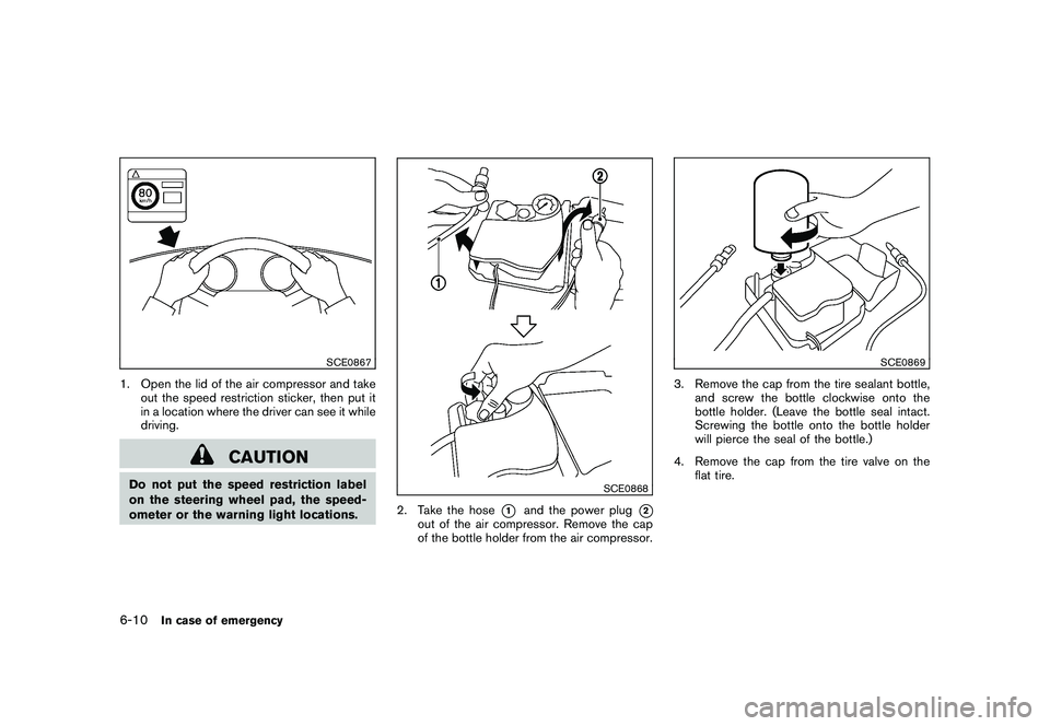
SCE0867
1. Open the lid of the air compressor and takeout the speed restriction sticker, then put it
in a location where the driver can see it while
driving.
CAUTION
Do not put the speed restriction label
on the steering wheel pad, the speed-
ometer or the warning light locations.
SCE0868
2. Take the hose
*1
and the power plug
*2
out of the air compressor. Remove the cap
of the bottle holder from the air compressor.
SCE0869
3. Remove the cap from the tire sealant bottle,and screw the bottle clockwise onto the
bottle holder. (Leave the bottle seal intact.
Screwing the bottle onto the bottle holder
will pierce the seal of the bottle.)
4. Remove the cap from the tire valve on the flat tire.
6-10
In case of emergency
Page 328 of 419
Black plate (326,1)
Model "Z34-D" EDITED: 2010/ 7/ 27
SCE0791
WARNING
Always follow the instructions below.
Failure to do so could result in damage
to the charging system and cause
personal injury.
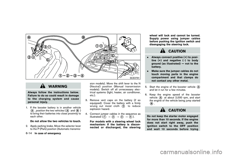
1. If the booster battery is in another vehicle*A
, position the two vehicles (
*A
and
*B)
to bring their batteries into close proximity to
each other.
Do not allow the two vehicles to touch.
2. Apply parking brake. Move the selector lever to the P (Park) position (Automatic transmis- sion models) . Move the shift lever to the N
(Neutral) position (Manual transmission
models) . Switch off all unnecessary elec-
trical systems (light, heater, air conditioner,
etc.) .
3. Remove vent caps on the battery (if so equipped) . Cover the battery with a firmly
wrung out moist cloth
*C
to reduce
explosion hazard.
4. Connect jumper cables in the sequence as illustrated (
*1
?
*2
?
*3
?
*4).
For models with a steering wheel lock
mechanism: If the battery is discon-
nected or discharged, the steering wheel will lock and cannot be turned.
Supply power using jumper cables
before pushing the ignition switch and
disengaging the steering lock.
CAUTION
.
Always connect positive (+) to posi-
tive (+) and negative ( �) to body
ground (as illustrated) — not to the
battery.
. Make sure the jumper cables do not
touch moving parts in the engine
compartment and that clamps do
not contact any other metal.
5. Start the engine of the booster vehicle
*A
and let it run for a few minutes.
6. Keep the engine speed of the booster vehicle
*A
at about 2,000 rpm, and start
the engine of the vehicle being jump started
*B.
CAUTION
Do not keep the starter motor engaged
for more than 10 seconds. If the engine
does not start right away, push the
ignition switch to the OFF position
and wait 10 seconds before trying
6-14
In case of emergency
Page 331 of 419

Black plate (329,1)
Model "Z34-D" EDITED: 2010/ 7/ 27
For information about towing your vehicle behind
a recreational vehicle (RV) , see “FLAT TOW-
ING” in the “9. Technical and consumer
information” section of this manual.
SCE0792
TOWING RECOMMENDED BY
NISSAN (except for NISMO models)NISSAN recommends that your vehicle be
towed with the driving (rear) wheels off the
ground or place the vehicle on a flat bed truck as
illustrated.
CAUTION
.Never tow automatic transmission
models with the rear wheels on the
ground or four wheels on the
ground (forward or backward) , as
this may cause serious and expen-
sive damage to the drivetrain. If it is necessary to tow the vehicle with
the front wheels raised, always use
towing dollies under the rear
wheels.
. When towing rear wheel drive mod-
els with the front wheels on the
ground or on towing dollies: Push
the ignition switch to the ACC or ON
position, and secure the steering
wheel in a straight-ahead position
with a rope or similar device. For
models with a steering wheel lock
mechanism: Never secure the steer-
ing wheel by selecting the LOCK
In case of emergency
6-17
Page 332 of 419

Black plate (330,1)
Model "Z34-D" EDITED: 2010/ 7/ 27
position. This may damage the
steering lock mechanism.
. If you have to tow manual transmis-
sion models with the rear wheels on
the ground (if you do not use towing
dollies) or four wheels on the
ground:
— Push the ignition switch to the
ON position and turn off all
accessories.
— Always release the parking brake.
— Move the transmission shift le- ver to the N (Neutral) position.
— Observe the following restricted towing speeds and distances for
manual transmission models
only:
.
Rear wheels on the ground:
Speed: Below 50 MPH (80
km/h)
Distance: Less than 50 miles
(80 km)
.
Four wheels on the ground:Speed: Below 70 MPH (112
km/h)
Distance: Less than 500 miles
(800 km)
— If the speed or distance must necessarily be greater, remove
the propeller shaft before tow-
ing to prevent damage to the
drivetrain.
6-18
In case of emergency
Page 334 of 419
Black plate (332,1)
Model "Z34-D" EDITED: 2010/ 7/ 27
SCE0793
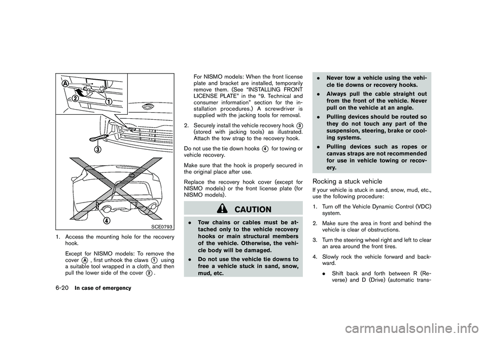
1. Access the mounting hole for the recoveryhook.
Except for NISMO models: To remove the
cover
*A
, first unhook the claws
*1
using
a suitable tool wrapped in a cloth, and then
pull the lower side of the cover
*2. For NISMO models: When the front license
plate and bracket are installed, temporarily
remove them. (See “INSTALLING FRONT
LICENSE PLATE” in the “9. Technical and
consumer information” section for the in-
stallation procedures.) A screwdriver is
supplied with the jacking tools for removal.
2. Securely install the vehicle recovery hook
*3
(stored with jacking tools) as illustrated.
Attach the tow strap to the recovery hook.
Do not use the tie down hooks
*4
for towing or
vehicle recovery.
Make sure that the hook is properly secured in
the original place after use.
Replace the recovery hook cover (except for
NISMO models) or the front license plate (for
NISMO models) .
CAUTION
. Tow chains or cables must be at-
tached only to the vehicle recovery
hooks or main structural members
of the vehicle. Otherwise, the vehi-
cle body will be damaged.
. Do not use the vehicle tie downs to
free a vehicle stuck in sand, snow,
mud, etc. .
Never tow a vehicle using the vehi-
cle tie downs or recovery hooks.
. Always pull the cable straight out
from the front of the vehicle. Never
pull on the vehicle at an angle.
. Pulling devices should be routed so
they do not touch any part of the
suspension, steering, brake or cool-
ing systems.
. Pulling devices such as ropes or
canvas straps are not recommended
for use in vehicle towing or recov-
ery.
Rocking a stuck vehicleIf your vehicle is stuck in sand, snow, mud, etc.,
use the following procedure:
1. Turn off the Vehicle Dynamic Control (VDC)
system.
2. Make sure the area in front and behind the vehicle is clear of obstructions.
3. Turn the steering wheel right and left to clear an area around the front tires.
4. Slowly rock the vehicle forward and back- ward.
.Shift back and forth between R (Re-
verse) and D (Drive) (automatic trans-
6-20
In case of emergency