Page 81 of 706

2-48 Seat and restraint systems
2
Deployment of front airbags
N00408000550
The front airbags and driver’s knee airbag ARE DESIGNED TO DEPLOY when… The front airbags and driver’s knee airbag are designed to
deploy when the vehicle suffers a moderate to severe frontal
impact. A typical condition is shown in the illustration to the
left.
The front airbags and driver’s knee airbag are designed to
deploy only in certain moderate to severe frontal collisions
within the shaded area between the arrows in the illustration to
the right.
The front airbags and driver’s knee airbag will deploy if the
impact to the vehicle’s main structure is above a specific
threshold level. The threshold level is approximately 15 mph
(25 km/h) for a frontal collision straight into a solid flat wallthat does not bend or deform. If the impact to the vehicle’s
main structure is below this threshold level, the front airbags
and driver’s knee airbag may not deploy. This threshold level
may also be higher if the vehicle hits something that absorbs
the impact, either by bending or moving (for example, another
stationary vehicle, a pole or a guard rail).
The beginning stage of airbag inflation is the most forceful,
and can cause serious injuries or death if you are too close to
the deploying airbag. Accordingly, it is important that you
always wear the available seat belt.
Head-on collision with a solid wall at
speeds of approx. 15 mph (25 km/h) or
higherModerate to severe frontal impact within
the shaded area between the arrows
BK0125300US.book 48 ページ 2010年5月18日 火曜日 午後1時53分
Page 82 of 706
Seat and restraint systems
2-49
2
The front airbags and driver’s knee airbag MAY NOT
DEPLOY when … In certain types of front collisions, the front airbags and
driver’s knee airbag may not deploy, even if the deformation of
the body seems to be large, because the vehicle’s body struc-
ture is designed to absorb the impact and deform in order to
help protect the occupants. Some typical situations where the
front airbags and driver’s knee airbag may not deploy are
shown in the illustrations.
Because the front airbags and driver’s knee airbag do not pro-
tect the occupant in all types of frontal collisions, be sure to
always wear your seat belts properly.
Collision with a utility pole, tree or other narrow objects
Collision where the vehicle slides under the rear body of a
truck
Oblique frontal impact
BK0125300US.book 49 ページ 2010年5月18日 火曜日 午後1時53分
Page 91 of 706
2-58 Seat and restraint systems
2
The side airbag and curtain airbag MAY NOT
DEPLOY when … In certain types of side collisions, the side airbag and curtain
airbag may not deploy, even if the deformation of the body
seems to be large, because the vehicle’s body structure is
designed to absorb the impact and to deform in order to help
protect the occupants. Some typical situations where the side
airbag and curtain airbag may not deploy are shown in the
illustrations.
Because the side airbags and curtain airbags do not protect the
occupant in all types of side collisions, be sure to always wear
your seat belts properly.
Side impact in an area away from the passenger compartment
Motorcycle or other similar small vehicle collision with the
side of vehicle
Collision with a utility pole, tree or other narrow object
BK0125300US.book 58 ページ 2010年5月18日 火曜日 午後1時53分
Page 408 of 706
Driving safety
4-15
4
Refitting the covers1. With each cover, put the tabs (C) on the cover in the holes
(D) in the roof.
2. Slide the cover (B) toward the rear of the vehicle to install
it.
Trailer towing
N00629800188
WA R N I N G
!�Do not use this vehicle for trailer towing. It may not
be possible to maintain control or adequate braking.
BK0125300US.book 15 ページ 2010年5月18日 火曜日 午後1時53分
Page 574 of 706
For emergencies
6-19
6
Wheel covers
(if so equipped)
N00849400179
To r e m o v e Wrap the tip of the bar with a cloth, insert it deeply into the
notch provided in the wheel cover, and pry the cover away
from the wheel.
Using the same procedure at the other wheel cover notches,
work the wheel cover away from the wheel to remove it com-
pletely. NOTE�The wheel cover is made of plastic. Be careful when pry-
ing it off.
To install
CAUTION
!�Trying to remove the wheel cover with only your
bare hands can seriously injure your fingers.
CAUTION
!�Before installing the wheel cover to the wheel, make
sure that the tabs (A) on the back of the wheel cover
correctly engage the ring (B) to prevent the wheel
cover from coming off. Do not install a wheel cover
that has broken tabs.
Ty p e 1
Ty p e 2
BK0125300US.book 19 ページ 2010年5月28日 金曜日 午後2時56分
Page 579 of 706

6-24 For emergencies
6
On snowy or icy roads �When driving on a road covered with snow or ice, use
snow tires. Tire chains cannot be used on your vehicle.
There may be state or local regulations about using snow
tires. Always check the regulations in your local area
before using them. Refer to the section entitled “Snow
tires” on page 7-39 and “Tire chains” on page 7-39.
�Drive slowly. Do not make sudden starts or stops, sharp
turns, or slam on the brakes.
�Allow extra distance between your vehicle and the vehicle
in front of you, and avoid sudden braking.
�If a skid occurs when the accelerator pedal is depressed,
take your foot off the pedal. Steer gently in the direction
of the skid.
�Your vehicle is equipped with an anti-lock braking system
(ABS). Hold the brake pedal down firmly and keep it
depressed. Do not pump the brake pedal which will result
in reduced braking performance.
�After parking on snowy or icy road, it may be difficult to
move your vehicle due to freeze-up of the brake. Depress
the accelerator pedal little by little to move the vehicle
after confirming safety of the vehicle.
On a bumpy or rutted roadDrive as slow as possible when driving on bumpy or rutted
roads or over potholes etc.
CAUTION
!�Do not depress the accelerator pedal rapidly. The
vehicle could start moving when it breaks free from
the ice, possibly resulting in an accident.
CAUTION
!�Driving on bumpy, rutted roads or over potholes can
damage the tires and wheels.
Wheels with low-profiles tires or under-inflated tires
are especially at risk for damage.�The vehicle’s body, bumper, muffler and other parts
may be damaged if the vehicle is:
• driven over a step (for example, at the entrance or
exit of a parking lot);
• parked too closely against a curb or parking block,
or by the side of a road with curbstones;
• driven on a steep slope;
BK0125300US.book 24 ページ 2010年5月18日 火曜日 午後1時53分
Page 610 of 706

Vehicle care and maintenance
7-31
7
Size DesignationEXAMPLE: P215/65R15
NOTE�European/Japanese metric tire sizing is based on Euro-
pean/Japanese design standards. Tires designed to these
standards have the tire size molded into the sidewall
beginning with the section width. The letter “P” is
absent from this tire size designation. Example:
215/65R15 96H.
�LT (Light Truck) -metric tire sizing is based on U.S.A.
design standards. The size designation for LT-metric
tires is the same as for P-metric tires except for the let-
ters “LT” that are molded into the sidewall preceding
the size designation. Example: LT235/85R16.�Temporary spare tires are high pressure compact spares
designed for temporary emergency use only. Tires
designed to this standard have the letter “T” molded
into the sidewall preceding the size designation. Exam-
ple: T145/80D18 103M.
Service DescriptionEXAMPLE: 95H
PPassenger car tire size based on U.S.A. design
standards
215 Section width in millimeters (mm.)
65Aspect ratio in percent (%)
Ratio of section height to section width of tire.
RConstruction code
• “R” means radial construction.
• “D” means diagonal or bias construction.
15 Rim diameter in inches (in)
95Load index
A numerical code associated with the maximum
load a tire can carry.
HSpeed symbol
A symbol indicating the range of speeds at
which a tire can carry a load corresponding to its
load index under certain operating conditions.
The maximum speed corresponding to the speed
symbol should only be achieved under specified
operating conditions. (i.e. tire pressure, vehicle
loading, road conditions and posted speed lim-
its)
BK0125300US.book 31 ページ 2010年5月18日 火曜日 午後1時53分
Page 670 of 706
Vehicle care and maintenance
7-91
7
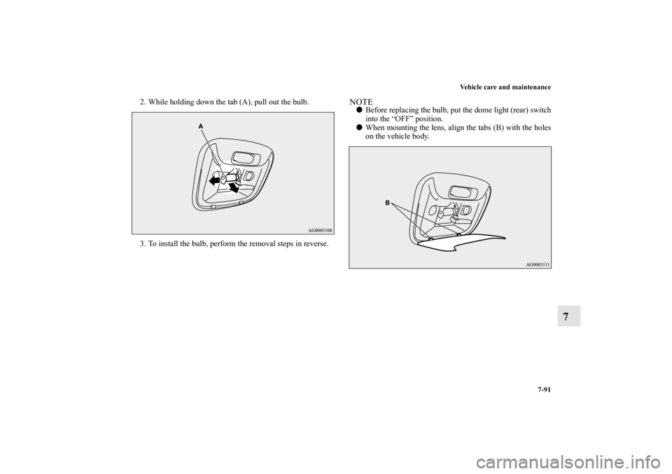
2. While holding down the tab (A), pull out the bulb.
3. To install the bulb, perform the removal steps in reverse.
NOTE�Before replacing the bulb, put the dome light (rear) switch
into the “OFF” position.
�When mounting the lens, align the tabs (B) with the holes
on the vehicle body.
BK0125300US.book 91 ページ 2010年5月18日 火曜日 午後1時53分


 on the cover in the holes
(D) in the roof.
2. Slide the cover (B) toward the rear of the vehicle to install
it.
Trailer t")

N00849400179
To r e m o v e Wrap the tip of the bar with a cloth, insert it deeply into the
notch provided in the wheel cover, and pry the cover")