Page 444 of 700

N00760000050
You can change the following functions to match your prefer-
ence.
�Enable automatic air control:")
Comfort controls
5-45
5
Personalizing the air selection (Changing the function
setting)
N00760000050
You can change the following functions to match your prefer-
ence.
�Enable automatic air control:
When the mode selection dial or the blower speed selec-
tion dial is set to the “AUTO” position, the air selection
switch will also be automatically controlled.
�Disable automatic air control:
Even when the mode selection dial or the blower speed
selection dial is set to the “AUTO” position, the air selec-
tion switch will not be automatically controlled.
�Changing the settings
Press the air selection switch for about 10 seconds or
longer.
When the setting has changed, the system will beep and
the indicator light will flash.
• When the setting has changed from enabled to disabled,
the system will beep three times and the indicator will
flash three times.
• When the setting has changed from disabled to enabled,
the system will beep two times and the indicator light
will flash three times.
NOTE�The factory setting is “Enable automatic air control”.
�While the mode selection dial is set to the “ ” position,
the air selection will automatically change to the outside
air position, even if the system is set to “Disable auto-
matic air control”, in order to prevent windows from fog-
ging up.
BK0119300US.book 45 ページ 2010年5月21日 金曜日 午前10時13分
Page 446 of 700

N00759800029
You can change the following functions to match your prefer-
ence.
�Enable automatic air")
Comfort controls
5-47
5
Personalizing the air conditioning switch (Changing
the function setting)
N00759800029
You can change the following functions to match your prefer-
ence.
�Enable automatic air conditioning control:
When the mode selection dial or blower speed selection
dial has been set to the “AUTO” position or when the tem-
perature control dial has been set to the minimum temper-
ature, the air conditioning switch is automatically
controlled.
�Disable automatic air conditioning control:
The air conditioning switch is not automatically con-
trolled, unless the air conditioning switch is used.
�Changing the settings
Press the air conditioning switch for about 10 seconds or
longer.
When the setting has changed, the system will beep and
the indicator light will flash.
• When the setting has changed from enabled to disabled,
the system will beep three times and the indicator will
flash three times.
• When the setting has changed from disabled to enabled,
the system will beep two times and the indicator light
will flash three times.
NOTE�The factory setting is “Enable automatic air conditioning
control”.
�While the mode selection dial is set to the “ ” position,
the air conditioning will run automatically, even if the sys-
tem is set to “Disable automatic air conditioning control”,
in order to prevent windows from fogging up.
BK0119300US.book 47 ページ 2010年5月21日 金曜日 午前10時13分
Page 627 of 700
7-50 Vehicle care and maintenance
7
Passenger compartment fuse location tablePassenger compartment fuse location
Sub fuse block Main fuse block
No.
Symbol
Electrical system
Capacity
1 Heater 30 A*
2Stop lights
(Brake lights)15 A
3 Rear fog light 10 A
4 Windshield wiper 30 A
5 Optional 10 A
6 Door locks 20 A
7Radio15 A
8 Control unit relay 7.5 A
9Interior lights
(Dome lights)15 A
10 Hazard warning flasher 15 A
11 Rear window wiper 15 A
12 Gauges 7.5 A
13Cigarette lighter/Accessory
socket15 A
14 Ignition switch 10 A
15 Sunroof 20 A
16 Outside rearview mirrors 10 A
17 All-wheel drive system 10 A
18 Back-up lights 7.5 A
BK0119300US.book 50 ページ 2010年5月21日 金曜日 午前10時13分
Page 629 of 700

7-52 Vehicle care and maintenance
7
No.
Symbol
Electrical system
Capacity
1 Front fog lights 15 A
2 Engine 7.5 A
3 Automatic transaxle 20 A
4 Horn 10 A
5 Alternator 7.5 A
6 Headlight washer 20 A
7 Air conditioning 10 A
8/ETV/Oil cooler
fan (Twin
Clutch SST)Except for
vehicles with
turbocharger
15 A
ETVVehicles with
turbocharger
9 Security horn 20 A
10 Wiper deicer 15 A
11 — — —
12 Power gate 30 A
13 Daytime running lights 10 A
14Headlight
(high beam) (left)10 A
15Headlight
(high beam) (right)10 A
16Headlight
(low/high
beam) (left)Discharge 20 A
17Headlight
(low/high
beam) (right)Discharge 20 A
18Headlight
(low beam)
(left)Halogen 10 A
19Headlight
(low beam)
(right)Halogen 10 A
20ENG/POWERExcept for
vehicles with
turbocharger
10 A
I/C SPRAYVe h i c l e s w i t h
turbocharger
21 Ignition coil 10 A
22ENG/POWERVe h i c l e s w i t h
turbocharger20 A
ENG/POWERExcept for
vehicles with
turbocharger20 A
Fuel line heater 25 ANo.
Symbol
Electrical system
Capacity
BK0119300US.book 52 ページ 2010年5月21日 金曜日 午前10時13分
Page 633 of 700

7-56 Vehicle care and maintenance
7Replacement of light bulbs
N00942900219
Before replacing a bulb, be sure the light is off. Do not touch
the glass part of the new bulb with your bare fingers; the oil
from your skin will stay on the glass and dim or destroy the
bulb when it gets hot.NOTE�If you are unsure of how to carry out the work as required,
it is recommended that these procedures be carried out by
an authorized Mitsubishi Motors dealer or a repair facility
of your choice.
�Be careful not to scratch the vehicle body when removing
a light and lens.
�When it rains, or when the vehicle has been washed, the
inside of the lens sometimes becomes temporarily foggy.
This is the same phenomenon as when window glass mists
up on a humid day, and does not indicate a functional
problem.
When the light is switched on, the heat will remove the
fog. However, if water gathers inside the light, please
have it checked by an authorized Mitsubishi Motors
dealer or a repair facility of your choice.
Bulb capacity
N00943000099
The bulb should only be replaced with a new bulb with the
same rating and type. The type and rating are listed on the base
of the bulb.Outside
N00950300704
[Except for vehicles with high intensity discharge headlights]
CAUTION
!�Bulbs are extremely hot immediately after being
turned off.
When replacing a bulb, wait for it to cool sufficiently
before touching it. You could otherwise be burned.
Description
Wattage
ANSI Trade
No. or Bulb
type
1-Front turn signal
light 21 W WY21W
2-Head light, high
beam60 W9005
HB3Front
BK0119300US.book 56 ページ 2010年5月21日 金曜日 午前10時13分
Page 634 of 700
![MITSUBISHI LANCER 2011 8.G Owners Manual Vehicle care and maintenance
7-57
7
[For vehicles with high intensity discharge headlights]
NOTE�It is not possible to repair or replace only the bulb for the
side turn-signal light.
Check with an aut](/manual-img/19/7451/w960_7451-633.png "MITSUBISHI LANCER 2011 8.G Owners Manual Vehicle care and maintenance
7-57
7
[For vehicles with high intensity discharge headlights]
NOTE�It is not possible to repair or replace only the bulb for the
side turn-signal light.
Check with an aut")
Vehicle care and maintenance
7-57
7
[For vehicles with high intensity discharge headlights]
NOTE�It is not possible to repair or replace only the bulb for the
side turn-signal light.
Check with an authorized Mitsubishi Motors dealer or a
repair facility of your choice when the light needs to be
repaired or replaced.
3-Head light, low beam
(Halogen bulb)51 W9006
HB4
4-Front fog light (if so
equipped)55 W H11
5-Front side-marker
and parking light5 W WY5W
6- Side turn signal light 5 W —
Description
Wattage or Candle
power
ANSI Trade
No. or Bulb
type
1-Front turn signal
light 21 W WY21W
2-Daytime running
light27 W
1156
32 cp
3-Head light, low/high
beam (Discharge
bulb)35 W —
4- Front fog light 55 W H11
5-Front side-marker
and parking light5 W WY5W
6- Side turn signal light 5 W —
Description
Wa t t a g e
ANSI Trade
No. or Bulb
type
WA R N I N G
!�Check with an authorized Mitsubishi Motors dealer
or a repair facility of your choice when it is neces-
sary to repair a discharge headlight or to replace the
bulb.
The power circuit, bulb and electrodes generate high
voltages that may cause a severe electrical shock.
BK0119300US.book 57 ページ 2010年5月21日 金曜日 午前10時13分
Page 650 of 700
Vehicle care and maintenance
7-73
7
Front fog lights (except for vehicles with turbo-
charger)
(if so equipped)
N00943600705
1. Remove the screw (A) and pull the cover out.2. Remove the screws (B) and pull the entire light unit out.
BK0119300US.book 73 ページ 2010年5月21日 金曜日 午前10時13分
Page 651 of 700
7-74 Vehicle care and maintenance
7
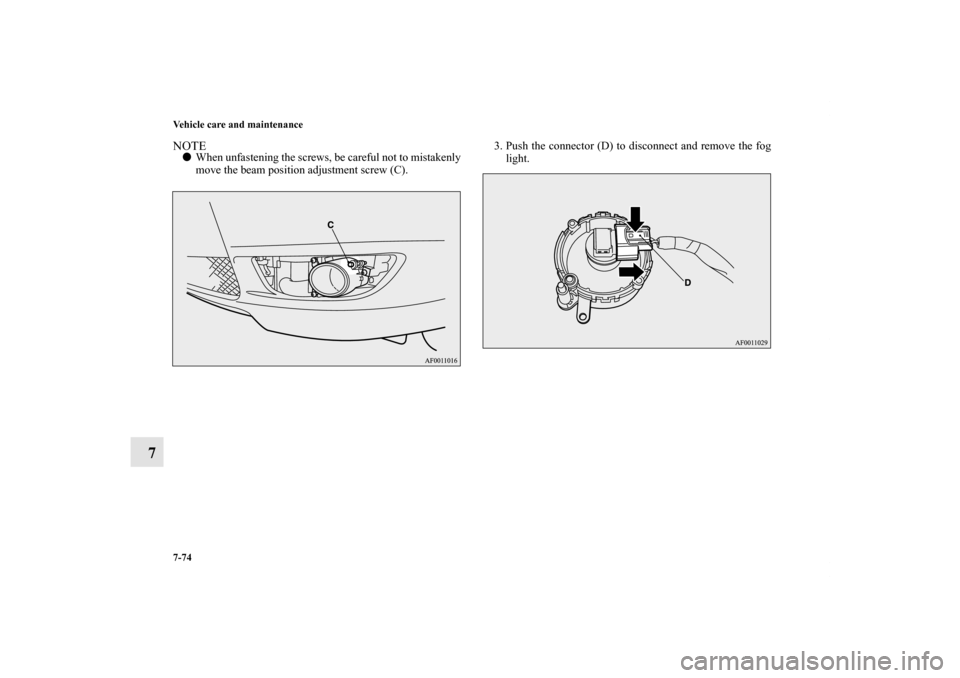
NOTE�When unfastening the screws, be careful not to mistakenly
move the beam position adjustment screw (C).3. Push the connector (D) to disconnect and remove the fog
light.
BK0119300US.book 74 ページ 2010年5月21日 金曜日 午前10時13分


(if so equipped)
N00943600705
1. Remove the screw (A) and pull the cover out.2. Remove the screws (B) an")