Page 445 of 514

7-18 Vehicle care and maintenance
7
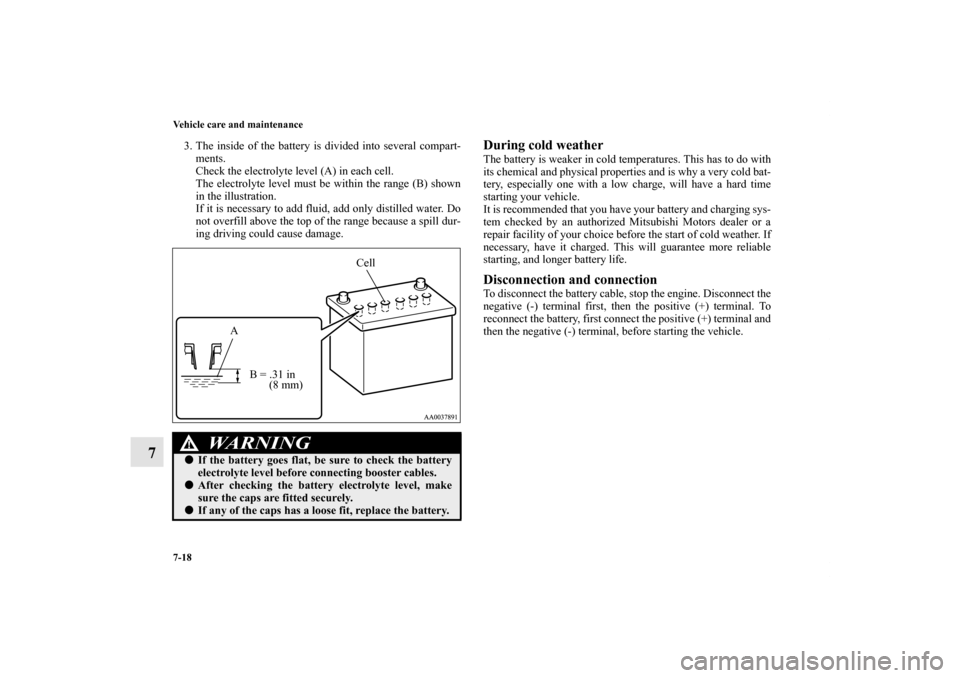
3. The inside of the battery is divided into several compart-
ments.
Check the electrolyte level (A) in each cell.
The electrolyte level must be within the range (B) shown
in the illustration.
If it is necessary to add fluid, add only distilled water. Do
not overfill above the top of the range because a spill dur-
ing driving could cause damage.
During cold weatherThe battery is weaker in cold temperatures. This has to do with
its chemical and physical properties and is why a very cold bat-
tery, especially one with a low charge, will have a hard time
starting your vehicle.
It is recommended that you have your battery and charging sys-
tem checked by an authorized Mitsubishi Motors dealer or a
repair facility of your choice before the start of cold weather. If
necessary, have it charged. This will guarantee more reliable
starting, and longer battery life.Disconnection and connectionTo disconnect the battery cable, stop the engine. Disconnect the
negative (-) terminal first, then the positive (+) terminal. To
reconnect the battery, first connect the positive (+) terminal and
then the negative (-) terminal, before starting the vehicle.
WA R N I N G
!�If the battery goes flat, be sure to check the battery
electrolyte level before connecting booster cables.�After checking the battery electrolyte level, make
sure the caps are fitted securely.�If any of the caps has a loose fit, replace the battery.
Cell
A
B = .31 in
(8 mm)
BK0121600US.book 18 ページ 2010年4月12日 月曜日 午前10時39分
Page 446 of 514

Vehicle care and maintenance
7-19
7
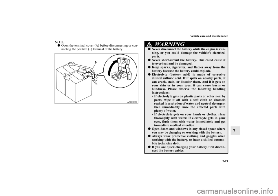
NOTE�Open the terminal cover (A) before disconnecting or con-
necting the positive (+) terminal of the battery.
WA R N I N G
!�Never disconnect the battery while the engine is run-
ning, or you could damage the vehicle’s electrical
parts. �Never short-circuit the battery. This could cause it
to overheat and be damaged. �Keep sparks, cigarettes, and flames away from the
battery because the battery could explode. �Electrolyte (battery acid) is made of corrosive
diluted sulfuric acid. If it spills on nearby parts, it
can crack, stain, or discolor them. And if it gets on
your skin or in your eyes, it can cause burns or
blindness. Please observe the following handling
instructions:
• If electrolyte gets on plastic parts or other nearby
parts, wipe it off with a soft cloth or chamois
soaked in a solution of water and neutral detergent
then immediately rinse the affected parts with
plenty of water.
• If electrolyte gets on your hands or clothes, rinse
thoroughly with water. If electrolyte gets in your
eyes, flush them with water immediately and get
immediate medical attention.
�Open doors and windows in any closed space where
you may be charging or working with the battery. �Always wear protective clothing and goggles when
working with the battery, or have a skilled automo-
bile technician do it. �If you are quick-charging your battery, first discon-
nect the battery cables.
BK0121600US.book 19 ページ 2010年4月12日 月曜日 午前10時39分
Page 456 of 514
Vehicle care and maintenance
7-29
7
Tire chains
N00940100073
Brake pedal free play
N00940300235
To check the brake pedal free play (A), turn off the engine and
press the brake pedal several times with your foot. Then press
the pedal down with your fingers until you first feel resistance.
Brake pedal free play:
.1 to .3 inch (3 to 8 mm)
If the free play is not within these limits, take your vehicle to
an authorized Mitsubishi Motors dealer or a repair facility of
your choice for adjustment.
CAUTION
!�Tire chains cannot be used on your vehicle. The
clearance between the chains and the body is not
sufficient to allow proper clearance, and the vehicle
body might be damaged.
BK0121600US.book 29 ページ 2010年4月12日 月曜日 午前10時39分
Page 459 of 514

7-32 Vehicle care and maintenance
7
NOTE�To meet government regulations and promote cleaner air,
your vehicle is equipped with an onboard diagnostic sys-
tem (OBD). The engine electronic control module that
controls OBD functions stores various data (especially
about the exhaust emissions). This data will be erased if
the battery cable is disconnected, which could make a
rapid diagnosis difficult. Do not disconnect the battery
cable when the engine malfunction indicator (“SERVICE
ENGINE SOON” or “Check engine light”) is on.Spark plugs
N00940900127
Spark plugs must fire properly for good engine performance
and emission-control.
Do not reuse them by cleaning or regapping. Change them at
the mileage listed in the “WARRANTY AND MAINTE-
NANCE MANUAL”.
Your vehicle may be equipped with iridium tipped spark plugs,
which are identified by marks on the ceramic. They do not
require replacement as frequently as the conventional type
spare plug and will last much longer.NOTE�Use the spark plugs listed under “Engine specifications”
on page 9-6 or plugs that are exactly the same. Other
plugs could cause engine damage, performance problems
or radio noise.Fuel hoses
N00941000011
Check the hose surfaces for any heat and mechanical damage,
hard and brittle rubber, cracking, tears, cuts and abrasions. Payspecial attention to the hoses closest to high heat sources such
as the exhaust manifold. Check all the hose connections, such
as clamps and couplings, to make sure they are secure and that
there are no leaks. If you see any wear or damage, replace the
hoses immediately.
Fuel system (tank, pipe line and connection, and
fuel tank filler tube cap)
N00941300131
Check these regularly for damage or leaks in the fuel lines and
connections. Check the fuel tank filler tube cap for damage or
looseness. Pay special attention to the fuel lines closest to high
heat sources such as the exhaust manifold.Evaporative emission control system (except
evaporative emission canister)
N00941400116
If the fuel-vapor vent line is clogged or damaged, the fuel-
vapor mixture will escape, polluting the air.
Have the system checked at an authorized Mitsubishi Motors
dealer at the mileage specified in the “WARRANTY AND
MAINTENANCE MANUAL”.
WA R N I N G
!�If you see a fuel leak or if you smell fuel, do not run
the engine. Any spark (including from the ignition),
flame or smoking material could cause an explosion
or fire. Call an authorized Mitsubishi Motors dealer
or a repair facility of your choice for assistance.
BK0121600US.book 32 ページ 2010年4月12日 月曜日 午前10時39分
Page 461 of 514

7-34 Vehicle care and maintenance
7
the pulleys as shown in the illustration with a force of about 22
pounds (100N).
Check the drive belt for cuts and cracks, and replace it if it is
damaged.
When replacing the belt with a new belt, make sure that there is
no interference between the belt and other engine components.
Then, check the tension of the belt at the designated point. The
deflection must be within the specifications.Amount of belt deflectionExhaust system
N00942200010
The best way to keep carbon monoxide gas from entering
inside your vehicle is to have the engine exhaust system prop-
erly serviced.
Have a competent mechanic inspect the complete exhaust sys-
tem and nearby body areas for broken, damaged, deteriorated,
or mispositioned parts if you notice any of the following:
�A change in the sound of the exhaust system
�The smell of exhaust fumes inside the vehicle
�The underside or rear of the vehicle is damaged
Also check the exhaust system each time the vehicle is raised
for lubrication, oil changes, or required service. Any open
seams or loose connections could let dangerous exhaust fumes
seep into the luggage compartment and passenger compart-
ments. Check for any of the following conditions: �Check for holes or exhaust gas leaks caused by corrosion
or damage.
�Check the joints and connections for looseness or exhaust
gas leaks.
�Check the rubber hangers and brackets for damage.Timing belt
N00942300037
The timing belt should be replaced with a new one at the mile-
age listed in the “WARRANTY AND MAINTENANCE
MANUAL”.Hood lock release mechanism and safety catch
N00942500042
The hood lock release mechanism and hood safety catch should
be checked, cleaned, and oiled when needed for easy move-
ment and to stop rust and wear. Use Multipurpose Grease
NLGI Grade 2 sparingly for all sliding parts of the hood latch
Standard value
Used belt
New belt
A.48 to .64 inch
(12.3 to 16.2 mm).52 to .59 inch
(13.2 to 15.1 mm).38 to .48 inch
(9.6 to 12.3 mm)B.33 to .42 inch
(8.4 to 10.7 mm).35 to .40 inch
(8.9 to 10.1 mm).24 to .30 inch
(6.2 to 7.5 mm)
WA R N I N G
!�Do not check or touch the drive belt with the engine
running, or serious injury or death may result.
WA R N I N G
!�Carbon monoxide gas from your vehicle’s exhaust is
poisonous. Breathing these fumes can cause uncon-
sciousness or death.
BK0121600US.book 34 ページ 2010年4月12日 月曜日 午前10時39分
Page 462 of 514

Vehicle care and maintenance
7-35
7
and release lever. Work the grease into the hood lock mecha-
nism until all the movable surfaces are covered.
Also, put a light coat of the same grease on the safety catch
wherever moving parts touch.
For cold and snowy weather
N00942600115
Ventilation slotsThe ventilation slots in front of the windshield should be kept
clear of leaves or brushed clear after a heavy snowfall, so that
the operation of the heating and ventilation systems will not be
impaired.WeatherstrippingTo prevent freezing of the weatherstripping on the doors,
engine hood, etc., they should be treated with silicone grease.Additional equipment (For regions where snow is
encountered)It is a good idea to carry a shovel or a short-handled spade in
the vehicle during the winter so that you can clear away snow
if you get stranded. A small hand-brush for sweeping snow off
the vehicle and a plastic scraper for the windshield, side and
rear window are also useful.
BK0121600US.book 35 ページ 2010年4月12日 月曜日 午前10時39分
Page 463 of 514
7-36 Vehicle care and maintenance
7Fuse links
N00942700099
The fuse links will melt to prevent a fire if a large current
attempts to flow through certain electrical systems.
In case of a melted fuse link, see your authorized Mitsubishi
Motors dealer or a repair facility of your choice for inspection
and replacement.
Fuses
N00942800869
Fuse block locationTo prevent damage to the electrical system from short-circuit-
ing or overloading, each individual circuit is equipped with a
fuse. The fuse blocks are located in the passenger compartment
and in the engine compartment. Passenger compartmentThe fuse block in the passenger compartment is located in front
of the driver’s seat at the position shown in the illustration.
BK0121600US.book 36 ページ 2010年4月12日 月曜日 午前10時39分
Page 464 of 514
Vehicle care and maintenance
7-37
7
Engine compartmentIn the engine compartment, the fuse blocks (A and B) are
located as shown in the illustration. Ty p e A
1. Push the lock lever.
2. Remove the fuse block cover.
BK0121600US.book 37 ページ 2010年4月12日 月曜日 午前10時39分