2011 MERCEDES-BENZ SLK300 clock
[x] Cancel search: clockPage 237 of 312
X
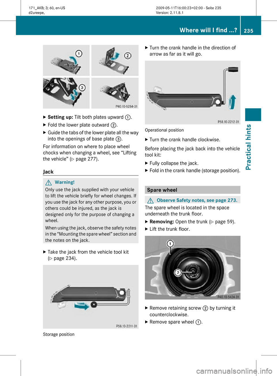
Setting up: Tilt both plates upward :.
X Fold the lower plate outward ;.
X Guide the tabs of the lower plate all the way
into the openings of base plate =.
For information on where to place wheel
chocks when changing a wheel, see “Lifting
the vehicle” ( Y page 277).
Jack G
Warning!
Only use the jack supplied with your vehicle
to lift the vehicle briefly for wheel changes. If
you use the jack for any other purpose, you or
others could be injured, as the jack is
designed only for the purpose of changing a
wheel.
When using the jack, observe the safety notes
in the “Mounting the spare wheel” section and
the notes on the jack.
X Take the jack from the vehicle tool kit
(Y page 234). Storage position X
Turn the crank handle in the direction of
arrow as far as it will go. Operational position
X
Turn the crank handle clockwise.
Before placing the jack back into the vehicle
tool kit:
X Fully collapse the jack.
X Fold in the crank handle (storage position). Spare wheel
G
Observe Safety notes, see page 273.
The spare wheel is located in the space
underneath the trunk floor.
X Removing: Open the trunk (Y page 59).
X Lift the trunk floor. X
Remove retaining screw ; by turning it
counterclockwise.
X Remove spare wheel :. Where will I find ...?
235Practical hints
171_AKB; 3; 60, en-US
d2ureepe, Version: 2.11.8.1 2009-05-11T16:00:23+02:00 - Seite 235 Z
Page 238 of 312
The spare wheel bolts are located under a
plastic cover on the outside of the spare
wheel rim.
X
Take off the spare wheel bolts.
For information on mounting the spare wheel,
see “Flat tire” ( Y page 273).
Storing the spare wheel after use If you wish to store the spare wheel after use,
carry out the following steps. Otherwise, the
spare wheel may not fit into the spare wheel
well.
!
Make sure the spare wheel is dry before
storing it.
X Take the valve extractor from the vehicle
tool kit ( Y page 234).
X Unscrew the valve cap from the valve of the
collapsible tire.
X Use the valve extractor to unscrew the
valve insert from the valve.
X Allow the air to escape.
i It may take a few minutes for the
collapsible tire to deflate completely.
X Use the valve extractor to screw the valve
insert back into the valve.
X Screw the valve cap back onto the valve.
X Place the valve extractor back into the
vehicle tool kit.
X Take the protective wrap from the vehicle
tool kit.
X Pull the protective wrap over the spare
wheel.
X Place the spare wheel into the spare wheel
well.
X Pierce the protective wrap with retaining
screw ;.
X Secure the spare wheel by turning retaining
screw ; clockwise. Vehicle status messages in the
multifunction display
Notes
Warning and malfunction messages appear in
the multifunction display located in the
instrument cluster.
Certain warning and malfunction messages
are accompanied by an audible signal.
Address these messages accordingly and
follow the additional instructions given in this
Operator’s Manual.
Selecting the Vehicle status message
memory menu in the control system
(Y page 101) displays both cleared and
uncleared messages.
High-priority messages appear in the
multifunction display in red color.
Certain messages of high priority cannot be
cleared from the multifunction display using
the reset button . (Y page 92) or button
&, *, U or V on the
multifunction steering wheel.
Other messages of high priority and
messages of less immediate priority can be
cleared from the multifunction display using
the reset button . or button &, *,
U or V on the multifunction steering
wheel. They are then stored in the Vehicle
status message memory menu
(Y page 101). Remember that clearing a
message will only make the message
disappear. Clearing a message will not
correct the condition that caused the
message to appear. G
Warning!
All categories of messages contain important
information which should be taken note of
and, where a malfunction is indicated,
addressed as soon as possible at an
authorized Mercedes-Benz Center.
Failure to repair the condition noted may
cause
damage not covered by the Mercedes- 236
Vehicle status messages in the multifunction display
Practical hints
171_AKB; 3; 60, en-US
d2ureepe,
Version: 2.11.8.1 2009-05-11T16:00:23+02:00 - Seite 236
Page 267 of 312
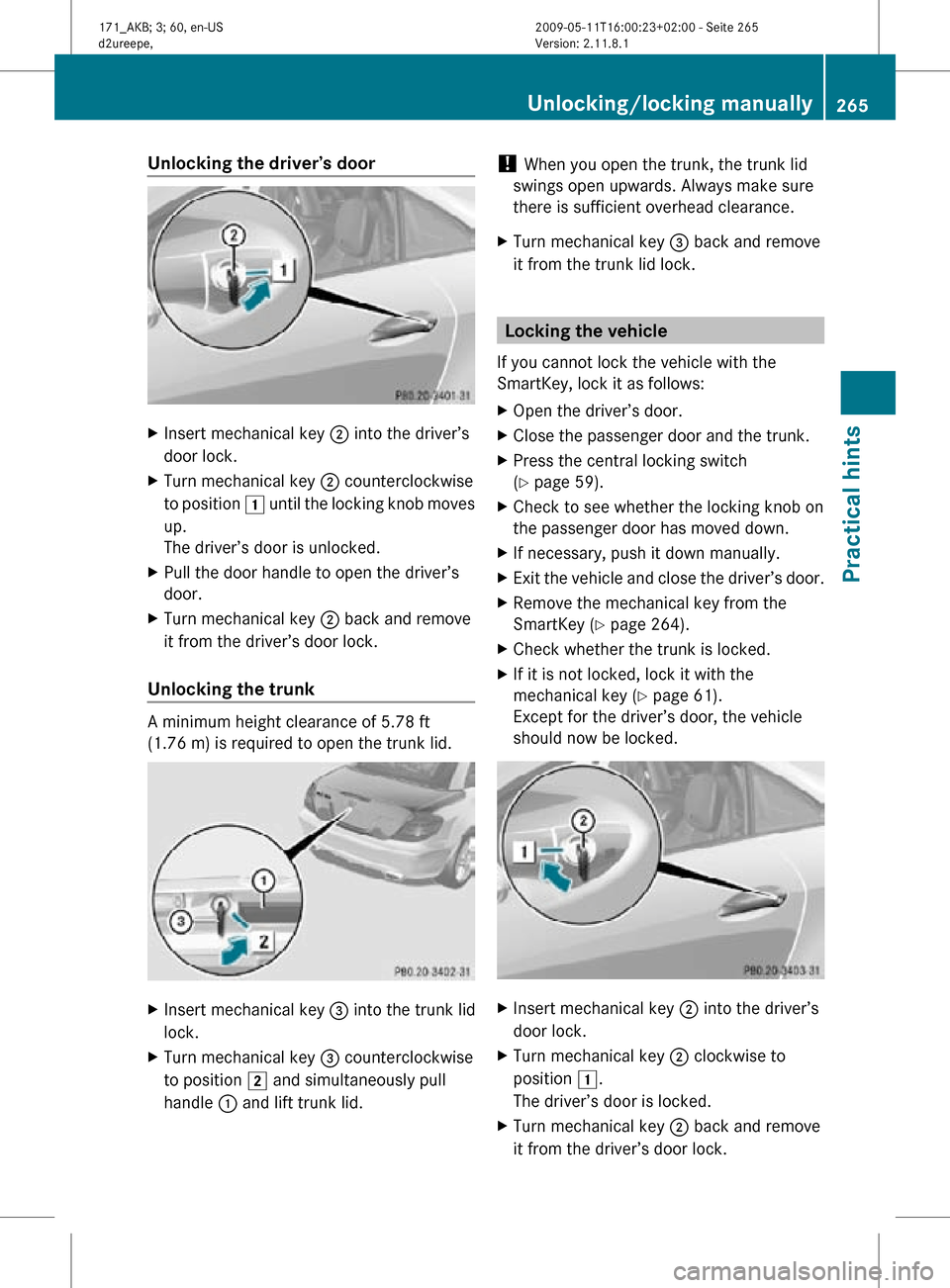
Unlocking the driver’s door
X
Insert mechanical key ; into the driver’s
door lock.
X Turn mechanical key ; counterclockwise
to position 1 until the locking knob moves
up.
The driver’s door is unlocked.
X Pull the door handle to open the driver’s
door.
X Turn mechanical key ; back and remove
it from the driver’s door lock.
Unlocking the trunk A minimum height clearance of 5.78 ft
(1.76 m) is required to open the trunk lid.
X
Insert mechanical key = into the trunk lid
lock.
X Turn mechanical key = counterclockwise
to position 2 and simultaneously pull
handle : and lift trunk lid. !
When you open the trunk, the trunk lid
swings open upwards. Always make sure
there is sufficient overhead clearance.
X Turn mechanical key = back and remove
it from the trunk lid lock. Locking the vehicle
If you cannot lock the vehicle with the
SmartKey, lock it as follows:
X Open the driver’s door.
X Close the passenger door and the trunk.
X Press the central locking switch
(Y page 59).
X Check to see whether the locking knob on
the passenger door has moved down.
X If necessary, push it down manually.
X Exit the vehicle and close the driver’s door.
X Remove the mechanical key from the
SmartKey (Y page 264).
X Check whether the trunk is locked.
X If it is not locked, lock it with the
mechanical key ( Y page 61).
Except for the driver’s door, the vehicle
should now be locked. X
Insert mechanical key ; into the driver’s
door lock.
X Turn mechanical key ; clockwise to
position 1.
The driver’s door is locked.
X Turn mechanical key ; back and remove
it from the driver’s door lock. Unlocking/locking manually
265Practical hints
171_AKB; 3; 60, en-US
d2ureepe, Version: 2.11.8.1 2009-05-11T16:00:23+02:00 - Seite 265 Z
Page 272 of 312
G
Observe Safety notes, see page 267.
R Only use 12-volt bulbs of the same type and
with the specified watt rating.
R Switch the lights off before changing a bulb
to prevent short circuits.
R Always use a clean lint-free cloth when
handling bulbs.
R Your hands should be dry and free of oil and
grease.
R If the newly installed bulb does not come
on, contact an authorized Mercedes-Benz
Center.
i Mercedes-Benz recommends using
Longlife (LL) bulbs. Replacing bulbs for front lamps
Before you start to replace a bulb for a front
lamp, do the following:
X Switch off the ignition.
X Turn the exterior lamp switch to position
$.
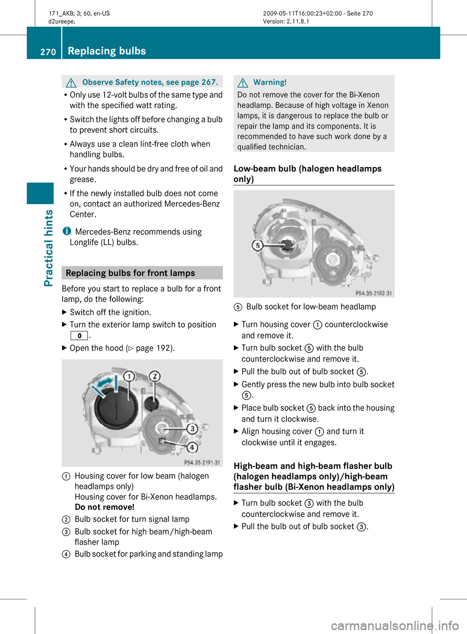
X Open the hood (Y page 192). :
Housing cover for low beam (halogen
headlamps only)
Housing cover for Bi-Xenon headlamps.
Do not remove!
; Bulb socket for turn signal lamp
= Bulb socket for high beam/high-beam
flasher lamp
? Bulb socket for parking and standing lamp G
Warning!
Do not remove the cover for the Bi-Xenon
headlamp. Because of high voltage in Xenon
lamps, it is dangerous to replace the bulb or
repair the lamp and its components. It is
recommended to have such work done by a
qualified technician.
Low-beam bulb (halogen headlamps
only) A
Bulb socket for low-beam headlamp
X Turn housing cover : counterclockwise
and remove it.
X Turn bulb socket A with the bulb
counterclockwise and remove it.
X Pull the bulb out of bulb socket A.
X Gently press the new bulb into bulb socket
A.
X Place bulb socket A back into the housing
and turn it clockwise.
X Align housing cover : and turn it
clockwise until it engages.
High-beam and high-beam flasher bulb
(halogen headlamps only)/high-beam
flasher bulb (Bi-Xenon headlamps only) X
Turn bulb socket = with the bulb
counterclockwise and remove it.
X Pull the bulb out of bulb socket =.270
Replacing bulbsPractical hints
171_AKB; 3; 60, en-US
d2ureepe,
Version: 2.11.8.1 2009-05-11T16:00:23+02:00 - Seite 270
Page 273 of 312
X
Gently press the new bulb into bulb socket
=.
X Place bulb socket = back into the housing
and turn it clockwise until it engages.
Front turn signal lamp bulb X
Turn bulb socket ; with the bulb
counterclockwise and remove it.
X Gently press onto the bulb and turn it
counterclockwise out of bulb socket ;.
X Gently press the new bulb into bulb
socket ; and turn it clockwise until it
engages.
X Place bulb socket ; back into the housing
and turn it clockwise until it engages.
Parking and standing lamp bulb X
Turn bulb socket ? with the bulb
counterclockwise and remove it.
X Pull the bulb out of bulb socket ?.
X Gently press the new bulb into bulb
socket ?.
X Place bulb socket ? back into the housing
and turn it clockwise until it engages. Replacing bulbs for rear lamps
Tail lamp unit Since replacing bulbs in the tail lamp unit is a
technically highly demanding process, we
recommend to have them replaced at an
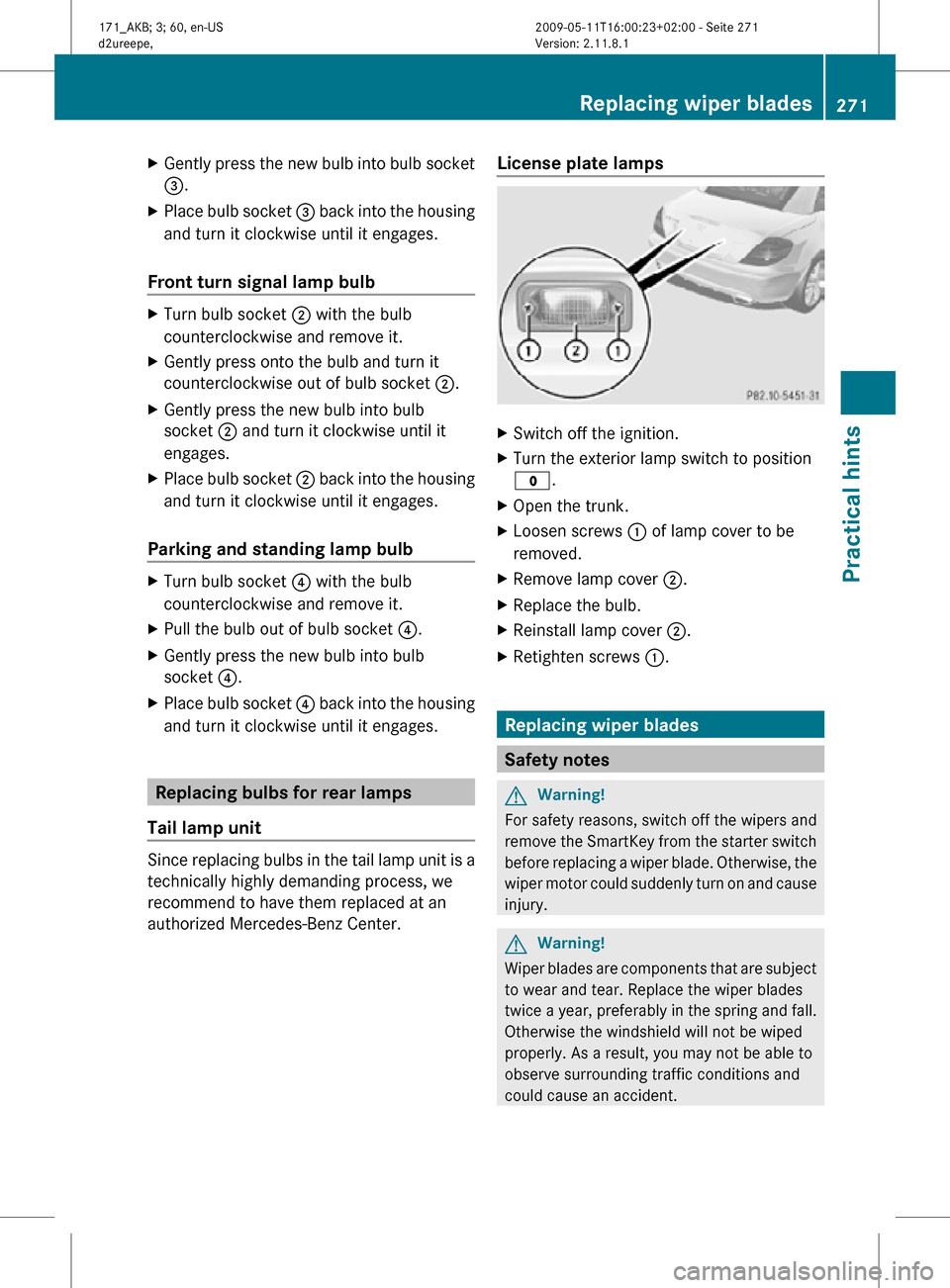
authorized Mercedes-Benz Center. License plate lamps X
Switch off the ignition.
X Turn the exterior lamp switch to position
$.
X Open the trunk.
X Loosen screws : of lamp cover to be
removed.
X Remove lamp cover ;.
X Replace the bulb.
X Reinstall lamp cover ;.
X Retighten screws :. Replacing wiper blades
Safety notes
G
Warning!
For safety reasons, switch off the wipers and
remove the SmartKey from the starter switch
before replacing a wiper blade. Otherwise, the
wiper motor could suddenly turn on and cause
injury. G
Warning!
Wiper blades are components that are subject
to wear and tear. Replace the wiper blades
twice a year, preferably in the spring and fall.
Otherwise the windshield will not be wiped
properly. As a result, you may not be able to
observe surrounding traffic conditions and
could cause an accident. Replacing wiper blades
271Practical hints
171_AKB; 3; 60, en-US
d2ureepe, Version: 2.11.8.1 2009-05-11T16:00:23+02:00 - Seite 271 Z
Page 280 of 312
Always try lifting the vehicle using the jack on
a level surface. However, should
circumstances require you to do so on a hill:
X
Place wheel chocks or other sizeable
objects on the downhill side in front of both
wheels on the side opposite to the side on
which the wheel is to be changed. G
Warning!
Only jack up the vehicle on level ground or on
slight inclines/declines. Otherwise, the
vehicle could fall off the jack and injure you or
others. X
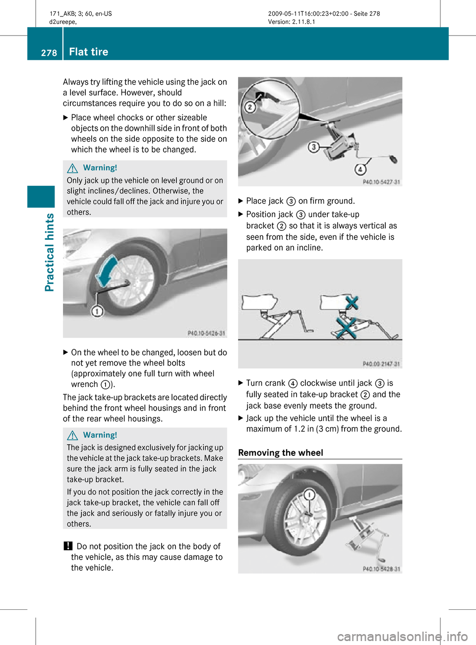
On the wheel to be changed, loosen but do
not yet remove the wheel bolts
(approximately one full turn with wheel
wrench :).
The jack take-up brackets are located directly
behind the front wheel housings and in front
of the rear wheel housings. G
Warning!
The jack is designed exclusively for jacking up
the vehicle at the jack take-up brackets. Make
sure the jack arm is fully seated in the jack
take-up bracket.
If you do not position the jack correctly in the
jack take-up bracket, the vehicle can fall off
the jack and seriously or fatally injure you or
others.
! Do not position the jack on the body of
the vehicle, as this may cause damage to
the vehicle. X
Place jack = on firm ground.
X Position jack = under take-up
bracket ; so that it is always vertical as
seen from the side, even if the vehicle is
parked on an incline. X
Turn crank ? clockwise until jack = is
fully seated in take-up bracket ; and the
jack base evenly meets the ground.
X Jack up the vehicle until the wheel is a
maximum of 1.2 in (3 cm) from the ground.
Removing the wheel 278
Flat tirePractical hints
171_AKB; 3; 60, en-US
d2ureepe,
Version: 2.11.8.1 2009-05-11T16:00:23+02:00 - Seite 278
Page 283 of 312
X
Turn the SmartKey in the starter switch to
position 1.
X Press I on electric air pump switch ;.
The electric air pump switches on and
inflates the collapsible tire.
X Inflate the collapsible tire to the
recommended tire inflation pressure as
specified for your vehicle ( Y page 300).
This should take approximately 5 minutes. G
Warning!
The air hose and the union nut can become
hot during inflation. Exercise proper caution
to avoid burning yourself when using the
equipment.
! Do not operate the electric air pump
longer than 6 minutes without interruption.
Otherwise it may overheat.
You may operate the air pump again after
it has cooled off.
! Compare the recommended tire inflation
pressure for your vehicle with the tire
inflation pressure on the yellow label
located on the spare wheel rim.
If the tire inflation pressure on the yellow
label on the spare wheel rim differs from
the values given in this Operator’s Manual,
inflate the tire to the recommended tire
inflation pressure given on the yellow label
on the spare wheel rim.
X Press 0 on electric air pump switch ;.
X Turn the SmartKey in the starter switch to
position 0.
X Version 1 only: If the tire inflation pressure
is above the recommended tire inflation
pressure as specified for your vehicle
(Y page 300), decrease tire pressure using
the vent screw on air hose ?.
X Version 2 only: If the tire inflation pressure
is above the recommended tire inflation
pressure as specified for your vehicle
(Y page 300), decrease tire pressure using
deflate button B. G
Observe Safety notes, see page 201.
X Detach the electric air pump.
X Reinstall collapsible tire valve cap.
X Version 1 only: Store electrical plug =
and air hose ? behind flap :.
X Version 2 only: Store electrical plug =
and the air hose back into the pump
housing bottom.
X Place the electric air pump back in its
designated storage space.
X Lower the vehicle.
Lowering the vehicle G
Warning!
Inflate collapsible tire only after the wheel is
properly attached.
Inflate the collapsible tire using the electric
air pump before lowering the vehicle.
X Lower the vehicle by turning the crank
counterclockwise until the vehicle is
resting fully on its own weight.
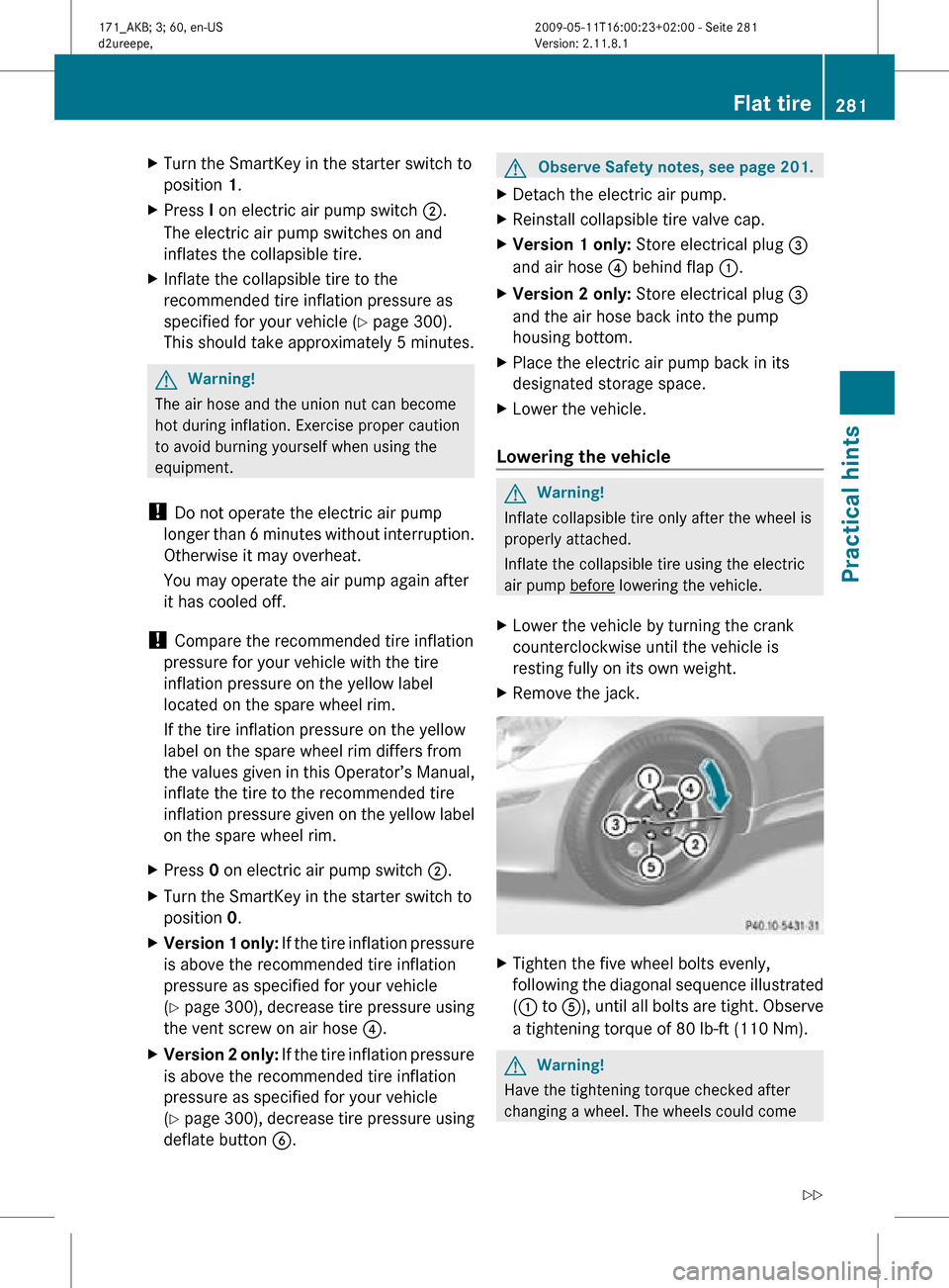
X Remove the jack. X
Tighten the five wheel bolts evenly,
following the diagonal sequence illustrated
(: to A), until all bolts are tight. Observe
a tightening torque of 80 lb-ft (110 Nm). G
Warning!
Have the tightening torque checked after
changing a wheel. The wheels could come Flat tire
281Practical hints
171_AKB; 3; 60, en-US
d2ureepe, Version: 2.11.8.1 2009-05-11T16:00:23+02:00 - Seite 281 Z
Page 285 of 312
G
Warning!
Do not place metal objects on the battery as
this could result in a short circuit.
Use
leak-proof batteries only to avoid the risk
of acid burns in the event of an accident.
Take care that you do not become statically
charged, e.g. by wearing synthetic clothing or
rubbing against textiles. For this reason, you
also should not pull or push the battery over
carpets or other synthetic materials.
Never touch the battery first. First touch the
outside body of the vehicle in order to release
any possible electrostatic charges.
Do not rub the battery with rags or cloths. The
battery could explode if touched due to
electrostatic charge or due to spark
formation.
! As any other battery, the battery may
discharge if you do not operate the vehicle
for an extended period of time. Have the
battery disconnected at a qualified
workshop or an authorized Mercedes-Benz
Center in such a case. You may also
connect an accessory battery charge unit
expressly approved by Mercedes-Benz for
your vehicle model to maintain the battery
charge. Contact an authorized Mercedes-
Benz Center for further information.
The battery, the battery ventilation hose
and the lateral plug must always be
securely installed when the vehicle is in
operation.
! Never loosen or detach battery terminal
clamps while the engine is running or the
SmartKey is in the starter switch.
Otherwise the alternator and other
electronic components could be severely
damaged.
Have the battery checked regularly at an
authorized Mercedes-Benz Center.
Refer to Maintenance Booklet for
maintenance intervals or contact an
authorized Mercedes-Benz Center for
further information. i
After battery power was interrupted, do
the following:
R Set the clock
(Y page 105).
R Synchronize the power windows
(Y page 79). Charging the battery
G
Warning!
Never charge a battery while still installed in
the vehicle unless the accessory battery
charge unit approved by Mercedes-Benz is
being used. Gases may escape during
charging and could cause an explosion that
may
result in personal injury, paint damage or
corrosion.
An accessory battery charge unit specially
adapted for Mercedes-Benz vehicles and
tested and approved by Mercedes-Benz is
available. It permits the charging of the
battery in its installed position. Contact an
authorized Mercedes-Benz Center for
information and availability.
Charge battery in accordance with the
separate instructions for the accessory
battery charger.
Have the battery charged at an authorized
Mercedes-Benz Center. If you charge the
battery yourself, follow the operating
instructions for your charging device.
Only use a battery charge unit with a
maximum charging voltage of 14.8 V.
X Charge battery in accordance with the
instructions of the battery charger
manufacturer. Jump starting
G
Warning!
Failure to follow these directions will cause
damage to the electronic components, and Jump starting
283
Practical hints
171_AKB; 3; 60, en-US
d2ureepe, Version: 2.11.8.1 2009-05-11T16:00:23+02:00 - Seite 283 Z