2011 MERCEDES-BENZ S-Class Start
[x] Cancel search: StartPage 422 of 524

inside of the fuel filler flap of your vehicle, if there is one). If your vehicle has tires which are a
different size to those on the tire and load data label or those specified in the tire pressure table,
if there is one, you should determine the correct tire pressure for these tires.
As an added safety feature, your vehicle has been equipped with a tire pressure monitor (TPMS).
An indicator lamp lights up if one or more of your tires are significantly underinflated. Accordingly,
when the low tire pressure indicator lamp lights up, you should stop and check your tires as soon
as possible, and inflate them to the proper pressure. Driving on a significantly underinflated tire
causes the tire to overheat and can lead to tire failure.
An excessively low tire pressure also increases fuel consumption, reduces the service life of the
tires and may impair the driving and braking characteristics of the vehicle. Please note that the
TPMS is not a substitute for proper tire maintenance and it is the driver's responsibility to maintain
correct tire pressure, even if underinflation has not reached the level at which the low tire
pressure indicator lamp of the TPMS lights up.
USA only:
Your vehicle has also been equipped with a TPMS malfunction indicator to indicate when the
system is not operating properly. The TPMS malfunction indicator is combined with the low tire
pressure indicator lamp. When the system detects a malfunction, the indicator lamp will flash
for approximately one minute and then remain illuminated. This sequence will continue upon
subsequent vehicle start-ups as long as the malfunction exists. When the malfunction indicator
is lit, the system may not be able to detect or signal low tire pressure as intended.
TPMS malfunctions may occur for a variety of reasons, including the installation of incompatible
replacement or alternate tires or wheels on the vehicle that prevent the TPMS from functioning
properly. Always check the TPMS malfunction indicator after replacing one or more tires or wheels
on your vehicle to ensure that the replacement or alternate tires and wheels allow the TPMS to
continue to function properly.420Warning and indicator lamps in the instrument clusterOn-board computer and displays
Page 433 of 524

Cigarette lighterGWarning
When leaving the vehicle, always remove the
SmartKey from the ignition lock. Always take
the SmartKey with you and lock the vehicle.
Do not leave children unattended in the
vehicle, even if they are secured in a child
restraint system, or with access to an
unlocked vehicle. A child's unsupervised
access to a vehicle could result in an accident
and/or serious personal injury. The children
could:
Rinjure themselves on parts of the vehicle
Rbe seriously or fatally injured through
excessive exposure to extreme heat or cold
Rinjure themselves or cause an accident with
vehicle equipment that can be operated
even if the SmartKey is removed from the
ignition lock or removed from the vehicle,
such as seat adjustment, steering wheel
adjustment, or the memory function
If children open a door, they could injure other
persons or get out of the vehicle and injure
themselves or be injured by following traffic.
Do not expose the child restraint system to
direct sunlight. The child restraint system's
metal parts, for example, could become very
hot, and the child could be burned on these
parts.
GWarning
Never touch the heating element or sides of
the lighter; they are extremely hot. Hold the
knob only.
Make sure any children traveling with you do
not injure themselves or start a fire with the
hot cigarette lighter.
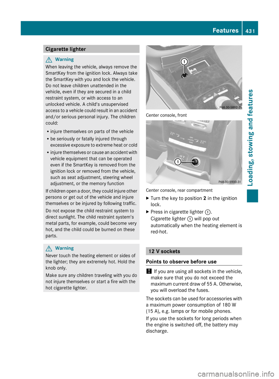
Center console, front
Center console, rear compartment
XTurn the key to position 2 in the ignition
lock.
XPress in cigarette lighter :.
Cigarette lighter : will pop out
automatically when the heating element is
red-hot.
12 V sockets
Points to observe before use
! If you are using all sockets in the vehicle,
make sure that you do not exceed the
maximum current draw of 55 A. Otherwise,
you will overload the fuses.
The sockets can be used for accessories with
a maximum power consumption of 180 W
(15 A), e.g. lamps or for mobile phones.
If you use the sockets for long periods when
the engine is switched off, the battery may
discharge.
Features431Loading, stowing and featuresZ
Page 437 of 524

pressed the SOS button. Carefully leave the
vehicle and move to a safe location. The
Response Center will automatically contact
local emergency officials with the vehicle's
approximate location if they receive an
automatic SOS signal and cannot make voice
contact with the vehicle occupants.
Roadside Assistance call buttonXOpen the stowage compartment under the
armrest ( Y page 423).XPress and hold Roadside Assistance
button : for more than two seconds.
A call to a Mercedes-Benz Roadside
Assistance Representative is initiated. The
indicator lamp in Roadside Assistance
button : flashes while the call is active.
The Connecting Call message appears in
the COMAND display and COMAND is
muted.
If a connection can be established, the Call
Connected message appears in the
COMAND display.
If a mobile phone network is available and
there is sufficient GPS reception, the mbrace
system transmits data to the Response
Center, for example:
R current location of the vehicle
R vehicle identification number
R vehicle model
R vehicle color
i The COMAND display shows that an
mbrace call is active. You can switch to the
navigation menu by pressing the
S button on COMAND during the call.
Spoken commands are not available.
A voice connection is established between
the Mercedes-Benz Roadside Assistance
Representative and the vehicle occupants.XDescribe the type of assistance needed.
The Mercedes-Benz Roadside Assistance
Representative either sends a qualified
Mercedes-Benz technician or organizes for
your vehicle to be transported to the nearest
authorized Mercedes-Benz Center. You may
be charged for services such as repair work
and/or towing. Further details are available
in your mbrace manual.
i If the indicator lamp in MB info call
button : flashes continuously and it was
not possible to establish a voice
connection to the Response Center, then
the mbrace system has failed to initiate a
Roadside Assistance call (e.g. the
corresponding cellular phone network is
not available). The Call Failed message
appears in the multifunction display.
The COMAND display shows the Call
could not be connected! message.
Press W to confirm the message.
XTo end a call: press the ~ button on the
multifunction steering wheel.
or
XPress the corresponding button for ending
a phone call on the COMAND telephone
keypad.
i Sign and Drive services 30
: you are not
charged for services such as jump-starting,
providing a few gallons of fuel for a fuel tank
that has been run dry or changing a flat tire
with the vehicle's own spare tire.
30 USA only.Features435Loading, stowing and featuresZ
Page 439 of 524

Downloading destinations in COMAND
iThe components and operating principles
of COMAND can be found on
( Y page 116).
Destination Download gives you access to a
database with over 10 million points of
interest (POIs) which can be downloaded to
the navigation system of your vehicle. If you
know the destination, you can download the
address or obtain the location of points of
interest (POIs) or important destinations in
the surrounding area.
You are prompted to confirm route guidance
to the entered address.
XUsing the COMAND controller XVY (slide)
and cVd (turn) to select Yes and confirm
by pressing W.
The system calculates the route and
subsequently starts the route guidance with
the address entered.
i If you select No, the address can be stored
in the address book.
i The Destination Download function is
available if the corresponding cellular
phone network is available and data
transfer is possible.
Search & Send
Points to observe before use
i To use Search & Send, your vehicle must
be equipped with mbrace and a navigation
system. You must also have an mbrace
service subscription.
"Search & Send" is a destination entry
service. A destination which is determined by
Google Maps ®
or Yahoo Local Maps ®
can be
forwarded directly to your vehicle's
navigation system using TELEAID.
Specifying and sending the destination
address
i Information about specific commands
such as address entry or sending an
address can be found on (either of) the
website(s). Each website works differently
and is subject to change.XGo to either http://
www.maps.google.com or http://
www.maps.yahoo.com and enter a
destination address in the entry field.XPress the relevant button on the website to
send the destination address to the e-mail
address of your mbrace account.XWhen the "Send" dialog window appears:
In the relevant field, enter the e-mail
address which you specified when
activating your mbrace account.XClick on "Send".
Calling up destination addresses
XPress the MB info call button to load the
destination address to your vehicle's
navigation system.
A display message appears, asking
whether navigation should be started.XSelect Yes.
The navigation start screen appears.XSelect Start.
Route guidance is started.
or
XSelect No.
The address is saved to the destination
memory for future use ( Y page 175).
i
If you have sent more than one
destination address, you have to make an
info call to load each individual address.
i Destination addresses are loaded in the
same order as the order in which they were
sent. If you own multiple Mercedes-Benz
vehicles with mbrace and activated mbrace
accounts:
Each destination address sent can be
accessed by every vehicle which is
connected with the relevant e-mail
address.
Features437Loading, stowing and featuresZ
Page 442 of 524

interference that may cause undesired
operation.
Unauthorized modification of this device
could void the user's authority to legally
operate the device.
Programming the remote control
Programming
GWarning!
Only press the transmitter button on the
integrated remote control if there are no
persons or objects present within the sweep
of the garage door. People could otherwise be
injured by the movement of the door.
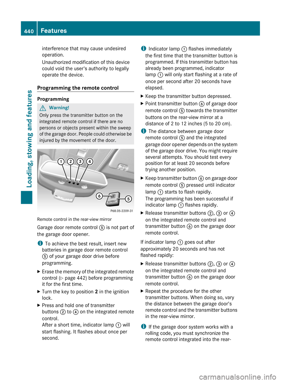
Remote control in the rear-view mirror
Garage door remote control A is not part of
the garage door opener.
iTo achieve the best result, insert new
batteries in garage door remote control
A of your garage door drive before
programming.
XErase the memory of the integrated remote
control (Y page 442) before programming
it for the first time.
XTurn the key to position 2 in the ignition
lock.
XPress and hold one of transmitter
buttons ; to ? on the integrated remote
control.
After a short time, indicator lamp : will
start flashing. It flashes about once per
second.
iIndicator lamp : flashes immediately
the first time that the transmitter button is
programmed. If this transmitter button has
already been programmed, indicator
lamp : will only start flashing at a rate of
once per second after 20 seconds have
elapsed.
XKeep the transmitter button depressed.XPoint transmitter button B of garage door
remote control A towards the transmitter
buttons on the rear-view mirror at a
distance of 2 to 12 inches (5 to 20 cm).
iThe distance between garage door
remote control A and the integrated
garage door opener depends on the system
of the garage door drive. You might require
several attempts. You should test every
position for at least 20 seconds before
trying another position.
XKeep transmitter button B on garage door
remote control A pressed until indicator
lamp : starts to flash rapidly.
The programming has been successful if
indicator lamp : flashes rapidly.
XRelease transmitter buttons ;, = or ?
on the integrated remote control and
transmitter button B on the garage door
remote control.
If indicator lamp : goes out after
approximately 20 seconds and has not
flashed rapidly:
XRelease transmitter buttons ;, = or ?
on the integrated remote control and
transmitter button B on the garage door
remote control.
XRepeat the procedure for the other
transmitter buttons. When doing so, vary
the distance between the garage door's
remote control and the transmitter buttons
in the rear-view mirror.
iIf the garage door system works with a
rolling code, you must synchronize the
remote control integrated into the rear-
440FeaturesLoading, stowing and features
Page 448 of 524

Vehicle equipment
iThis manual describes all the standard
and optional equipment of your vehicle
which was available at the time of
purchase. Country-specific differences are
possible. Note that your vehicle may not be
equipped with all functions described.
Engine compartment
Hood
Opening the hood
GWarning
Do not pull the release lever while the vehicle
is in motion. Otherwise, the hood could be
forced open by passing air flow.
This could cause the hood to come loose and
injure you and/or others.
GWarning
Hybrid vehicles: ensure that you read the
"HYBRID" supplement. You may otherwise fail
to recognize dangers.
GWarning
Do not open the hood when the engine is
overheated. You could be seriously injured.
Observe the coolant temperature gauge to
determine whether the engine may be
overheated. If you see flames or smoke
coming from the engine compartment, move
away from the vehicle. Wait until the engine
has cooled. If necessary, call the fire
department.
GWarning
There is a risk of injury if the hood is open,
even if the engine is not running.
Some engine components can become very
hot.
To avoid the risk of burns, only touch those
components described in the Operator's
Manual and observe the relevant safety notes.
GWarning
To help prevent personal injury, stay clear of
moving parts when the hood is open and the
engine is running.
The radiator fan may continue to run for
approximately 30 seconds or may even
restart after the engine has been turned off.
Stay clear of fan blades.
GWarning
The engine is equipped with a transistorized
ignition system. Because of the high voltage,
it is dangerous to touch any components
(ignition coils, spark plug sockets, diagnostic
socket) of the ignition system:
Rwith the engine running
Rwhile starting the engine
Rwhen the ignition is switched on and the
engine is turned manually
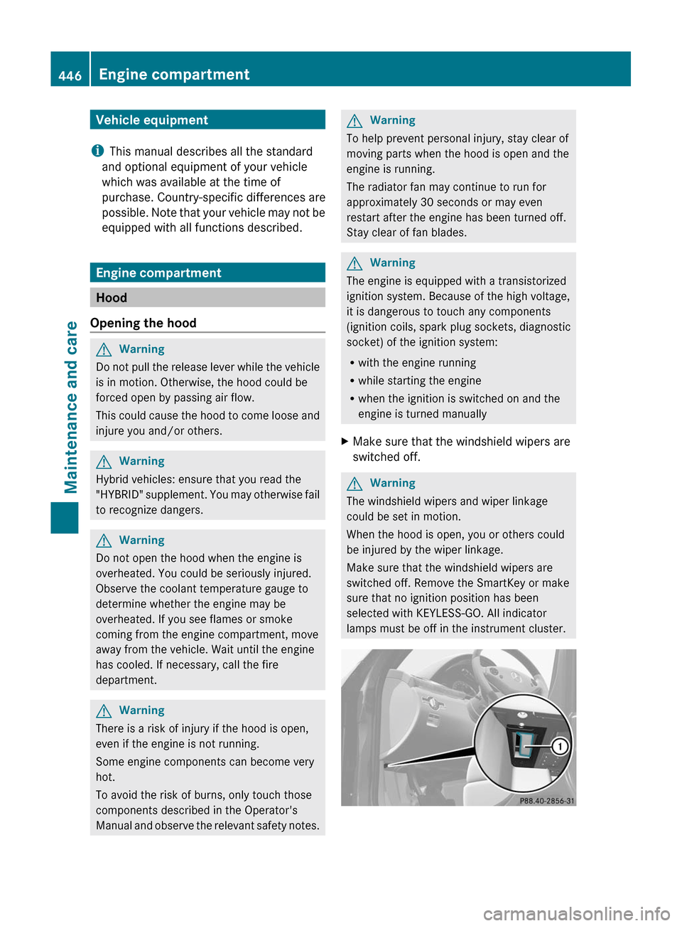
XMake sure that the windshield wipers are
switched off.
GWarning
The windshield wipers and wiper linkage
could be set in motion.
When the hood is open, you or others could
be injured by the wiper linkage.
Make sure that the windshield wipers are
switched off. Remove the SmartKey or make
sure that no ignition position has been
selected with KEYLESS-GO. All indicator
lamps must be off in the instrument cluster.
446Engine compartmentMaintenance and care
Page 451 of 524

If the engine is not at normal operating
temperature (e.g. if the engine was only
started briefly): repeat the measurement
after about 30 minutes.
If the Engine Oil Level Not Measurable
With Running Engine message appears:
XSwitch off the engine.XIf the engine is at normal operating
temperature: wait about five minutes
before carrying out the measurement.
If the engine is not at normal operating
temperature, e.g. if the engine was only
started briefly: wait about 30 minutes
before carrying out the measurement.
iIf you wish to cancel the measurement,
press the % button on the multifunction
steering wheel.
Adding engine oil
HEnvironmental note
When adding oil, take care not to spill any. If
oil enters the soil or waterways, it is harmful
to the environment.
! Only use engine oils and oil filters which
have been approved for vehicles with a
service system. A list of the engine oils and
oil filters that have been tested and
approved according to the Mercedes-Benz
specifications for service products can be
found on the Internet at http://
www.mbusa.com (USA only). Further
information on tested and approved engine
oils and oil filters can be obtained from any
authorized Mercedes-Benz Center.
The following causes engine failure or
damage to the exhaust system:
Rusing engine oils and oil filters that are
not specifically approved for the service
system
Rreplacing the engine oil and oil filter after
having exceeded the interval for
replacement prescribed by the
maintenance system
Rusing engine oil additives
Engine oil cap (example)
Engine oil cap (AMG vehicles, example: 8-cylinderengine)
XTurn cap : counter-clockwise and remove
it.
XAdd the amount of oil required.
Observe the specifications in the on-board
computer when doing so or fill carefully to the
maximum mark on the oil dipstick.
iVehicles with a dipstick: the difference in
quantity between the MIN mark and the
MAX mark on the dipstick is (depending on
the engine) approximately 1.6 to
2.1 US qt (1.5 to 2 l).
iAMG vehicles with 8-cylinder engines: the
difference in quantity between the MIN
mark and the MAX mark on the dipstick is
approximately 1.6 US qt (1.5 l).
! Do not add too much oil. If the oil level is
above the "max" mark on the dipstick, too
Engine compartment449Maintenance and careZ
Page 452 of 524

much oil has been added. This can lead to
damage to the engine or the catalytic
converter. Have excess oil siphoned off.
Further information on engine oil
(Y page 513).
XReplace cap : on the filler neck and
tighten clockwise.
Ensure that the cap locks into place
securely.
Checking and adding other service
products
Check coolant level
Only check the coolant level when the vehicle
is on a level surface and the engine has cooled
down.
XTurn the key to position 2 (Y page 299) in
the ignition lock.
On vehicles with KEYLESS-GO, press the
Start/Stop button twice (Y page 299).
XCheck the coolant temperature display in
the instrument cluster.
The coolant temperature must be below
158 ‡ (70 †).
GWarning
In order to avoid any potentially serious burns:
Ruse extreme caution when opening the
hood if there are any signs of steam or
coolant leaking from the cooling system, or
if the coolant temperature display indicates
that the coolant is overheated.
Rdo not remove the pressure cap on the
coolant reservoir if the coolant temperature
is above 158 ‡ (70 †). Allow the engine to
cool down before removing the cap. The
coolant reservoir contains hot fluid and is
under pressure.
Rusing a rag, slowly turn the cap
approximately 1/2 turn to relieve excess
pressure. If opened immediately, scalding
hot fluid and steam will be blown out under
pressure.
Rdo not spill antifreeze on hot engine parts.
Antifreeze contains ethylene glycol which
may burn if it comes into contact with hot
engine parts.
XSlowly turn cap : half a turn counter-
clockwise and allow excess pressure to
escape.
XTurn cap : further counter-clockwise and
remove it.
If the coolant is at the level of marker bar
= in the filler neck when cold, there is
enough coolant in coolant expansion
tank ;.
If the coolant is approximately 0.6 in
(1.5 cm) above marker bar = in the filler
neck when warm, there is enough coolant
in coolant expansion tank ;.
XIf necessary, add coolant that has been
tested and approved by Mercedes-Benz.
XReplace cap : and turn it clockwise as far
as it will go.
For further information on coolant, see
(Y page 515).
Windshield washer system/headlamp
cleaning system
The washer fluid reservoir is used for both the
windshield washer system and the headlamp
cleaning system.
450Engine compartmentMaintenance and care