2011 MERCEDES-BENZ GL350 BlueTEC height
[x] Cancel search: heightPage 108 of 376
driving without the steering wheel adjustment
feature locked could cause the driver to lose
control of the vehicle.
The electrical steering wheel adjustment
feature can be operated at any time.
Therefore, do not leave children unattended
in the vehicle, or with access to an unlocked
vehicle. A child's unsupervised access to a
vehicle could result in an accident and/or
serious personal injury.
Adjusting the steering wheel
manually
This function is only available in vehicles in
the USA.
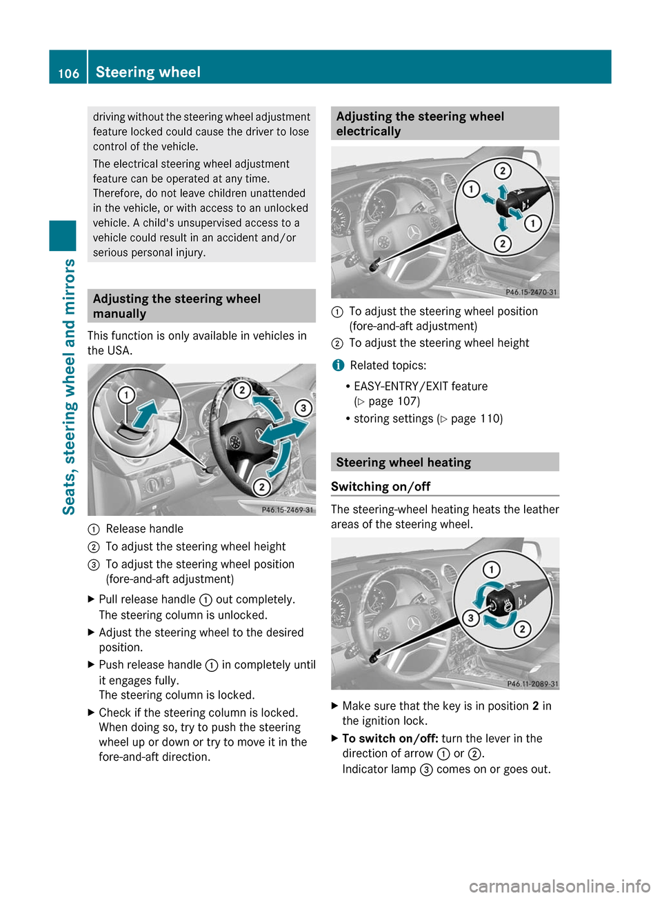
:Release handle;To adjust the steering wheel height=To adjust the steering wheel position
(fore-and-aft adjustment)XPull release handle : out completely.
The steering column is unlocked.XAdjust the steering wheel to the desired
position.XPush release handle : in completely until
it engages fully.
The steering column is locked.XCheck if the steering column is locked.
When doing so, try to push the steering
wheel up or down or try to move it in the
fore-and-aft direction.Adjusting the steering wheel
electrically:To adjust the steering wheel position
(fore-and-aft adjustment);To adjust the steering wheel height
i Related topics:
R EASY-ENTRY/EXIT feature
( Y page 107)
R storing settings ( Y page 110)
Steering wheel heating
Switching on/off
The steering-wheel heating heats the leather
areas of the steering wheel.
XMake sure that the key is in position 2 in
the ignition lock.XTo switch on/off: turn the lever in the
direction of arrow : or ;.
Indicator lamp = comes on or goes out.106Steering wheelSeats, steering wheel and mirrors
BA 164.8 USA, CA Edition B 2011; 1; 2, en-USd2sboikeVersion: 3.0.3.52010-04-21T15:08:44+02:00 - Seite 106
Page 126 of 376

XInsert the bulb holder and turn it clockwise.XClose the side trim panel (Y page 123).
License plate lamp
XSwitch off the lights.XOpen the tailgate.XRemove screws :.XRemove the license plate lamp.XReplace the bulb.XInsert the license plate lamp.XReplace and tighten screws :.
Setting the headlamps
:V vertical axis;H (horizontal) height, measured from the
center
Setting the headlamps correctly is extremely
important. Setting the high-beam headlamps
also sets the low-beam headlamps. (The term
headlamps covers both high and low beam.)
To check and adapt the headlamp setting,
proceed as follows:
XPark the vehicle on level ground at a
distance of 25 feet (7.6 m) from a wall or
similar.
XMake sure that the vehicle load is in the
normal range.
XSwitch on the L low-beam headlamps.
If the light of the headlamps is not distributed
as shown in the illustration above, follow the
instructions below:
XOpen the hood (Y page 294).
The adjustment screws are located under the
cover.
XInsert a suitable tool into the openings in
the cover. The directions of arrow =
and ? indicate the angle at which the tool
needs to be inserted in order to reach the
adjustment screws.
XTurn both screws uniformly until the
vertical setting corresponds to :. Turn the
screws clockwise to adjust the headlamp
upwards and counterclockwise to adjust it
downwards.
Gradation:
RScrew at arrow =: 0.67˚ angle of
inclination
RScrew at arrow ?: 0.50˚ angle of
inclination
The left and right headlamp need to be
adjusted individually.
iIf it is not possible to adjust the
headlamps accurately, have the
124Changing bulbsLights and windshield wipers
BA 164.8 USA, CA Edition B 2011; 1; 2, en-USd2sboikeVersion: 3.0.3.52010-04-21T15:08:44+02:00 - Seite 124
Page 176 of 376
GWarning!
Please be aware that by raising the vehicle
level, the center of gravity also rises.
Therefore, always ensure that the vehicle
level is as low as possible. With higher ride
height the ESP ®
may activate earlier in certain
situations.
GWarning!
Do not reduce the tire inflation pressure
before driving through sand. However, if you
do so, remember to correct the tire inflation
pressure before continuing your trip. Driving
with reduced tire inflation pressure increases
the risk of losing control of the vehicle and
rolling over.
General information
Read this section before driving your vehicle
off-road. Practice by traveling over more
gentle off-road terrain first.
Familiarize yourself with the characteristics
of your vehicle and the gear change process
before driving through difficult terrain.
The following driving systems are specially
adapted to off-road driving:
R off-road drive program (vehicles without
the Off-Road Pro engineering package)
( Y page 204)
R LOW RANGE off-road gear ( Y page 157)
R off-road ABS ( Y page 66)
R off-road 4ETS ( Y page 67)
R off-road ESP ®
(Y page 68)
R hill start assist
R differential locks ( Y page 207)
R DSR (Downhill Speed Regulation)
( Y page 203)
Observe the following notes:
R stop your vehicle and, if necessary, select
the off-road drive program (Y page 204) or
the LOW RANGE off-road gear
( Y page 157) before driving off-road.
R select a vehicle level that is suitable for the
terrain. Make sure there is always sufficient
ground clearance to prevent damage to the
vehicle.
R activate the differential lock if necessary.
R make sure that items of luggage and cargo
are stowed safely and are well secured
( Y page 268).
R always keep the engine running and in gear
when driving on a downhill gradient.
Activate DSR ( Y page 203).
R always keep the doors, tailgate, windows
and the tilt/sliding sunroof closed while the
vehicle is in motion.
R adapt the speed to suit the terrain
conditions. The more uneven, worn or
steeper the terrain is, the slower you should
drive.
R drive slowly and at an even speed through
the water. Ensure that a bow wave does not
form as you drive.
R drive with extreme care on unfamiliar off-
road routes where visibility is poor. For
safety reasons, get out of the vehicle first
and survey the off-road route.
R look out for obstacles, such as rocks, holes,
tree stumps and furrows.
R check the depth of water before fording
rivers and streams.
R do not stop in water and do not switch the
engine off.
R drive quickly on sand to overcome the
rolling resistance. Otherwise, the vehicle
could dig itself into the sand.
R do not jump with the vehicle. This
interrupts the vehicle's traction.
R always keep the engine running and in gear
when driving on slopes.
R do not shift the automatic transmission to
transmission position N.174Driving tipsDriving and parking
BA 164.8 USA, CA Edition B 2011; 1; 2, en-USd2sboikeVersion: 3.0.3.52010-04-21T15:08:44+02:00 - Seite 174
Page 275 of 376
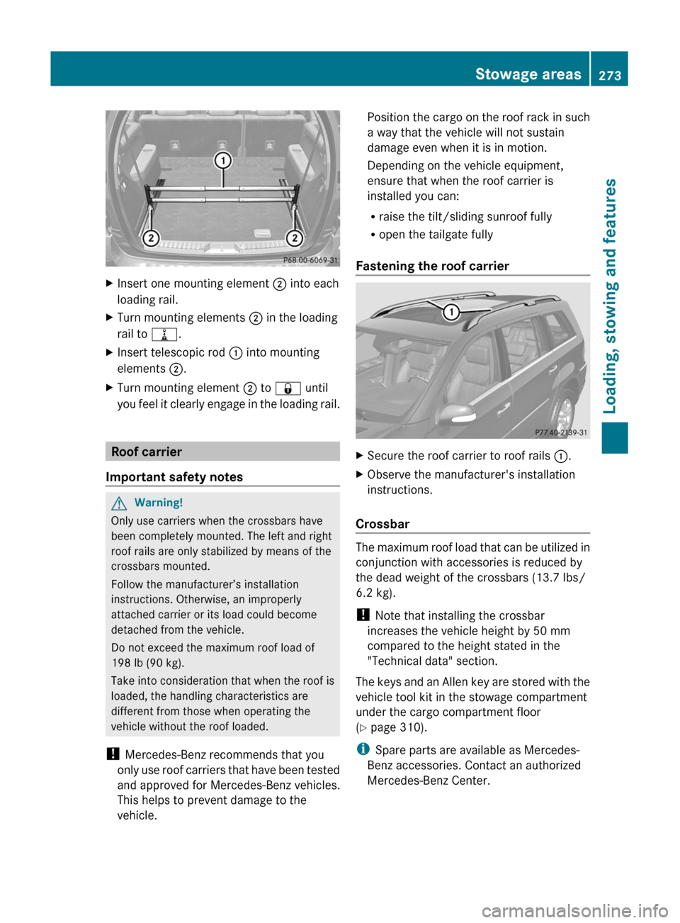
XInsert one mounting element ; into each
loading rail.XTurn mounting elements ; in the loading
rail to =.XInsert telescopic rod : into mounting
elements ;.XTurn mounting element ; to & until
you feel it clearly engage in the loading rail.
Roof carrier
Important safety notes
GWarning!
Only use carriers when the crossbars have
been completely mounted. The left and right
roof rails are only stabilized by means of the
crossbars mounted.
Follow the manufacturer’s installation
instructions. Otherwise, an improperly
attached carrier or its load could become
detached from the vehicle.
Do not exceed the maximum roof load of
198 lb (90 kg).
Take into consideration that when the roof is
loaded, the handling characteristics are
different from those when operating the
vehicle without the roof loaded.
! Mercedes-Benz recommends that you
only use roof carriers that have been tested
and approved for Mercedes-Benz vehicles.
This helps to prevent damage to the
vehicle.
Position the cargo on the roof rack in such
a way that the vehicle will not sustain
damage even when it is in motion.
Depending on the vehicle equipment,
ensure that when the roof carrier is
installed you can:
R raise the tilt/sliding sunroof fully
R open the tailgate fully
Fastening the roof carrierXSecure the roof carrier to roof rails :.XObserve the manufacturer's installation
instructions.
Crossbar
The maximum roof load that can be utilized in
conjunction with accessories is reduced by
the dead weight of the crossbars (13.7 lbs/
6.2 kg).
! Note that installing the crossbar
increases the vehicle height by 50 mm
compared to the height stated in the
"Technical data" section.
The keys and an Allen key are stored with the
vehicle tool kit in the stowage compartment
under the cargo compartment floor
( Y page 310).
i Spare parts are available as Mercedes-
Benz accessories. Contact an authorized
Mercedes-Benz Center.
Stowage areas273Loading, stowing and featuresBA 164.8 USA, CA Edition B 2011; 1; 2, en-USd2sboikeVersion: 3.0.3.52010-04-21T15:08:44+02:00 - Seite 273Z
Page 279 of 376
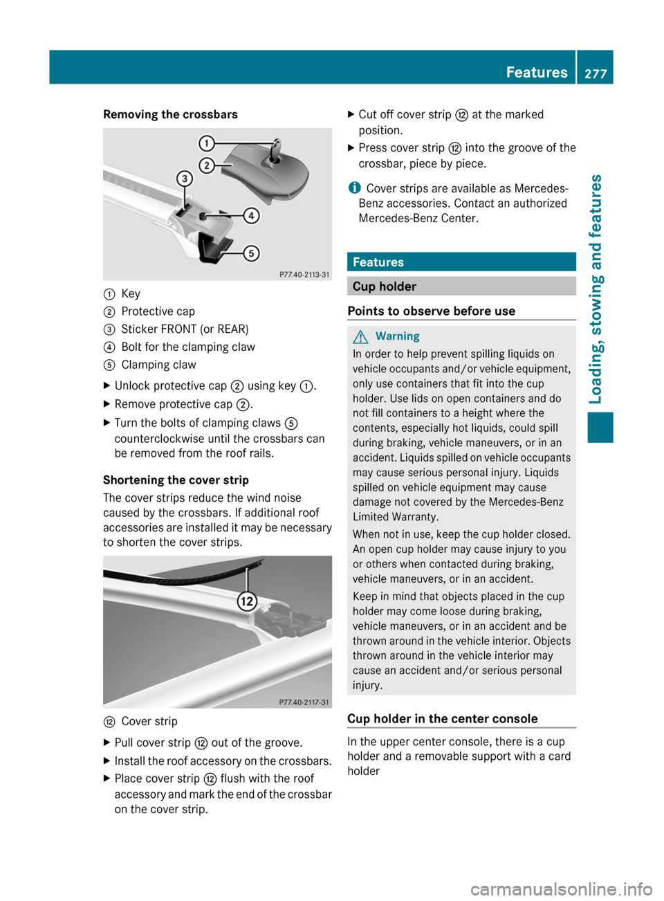
Removing the crossbars:Key;Protective cap=Sticker FRONT (or REAR)?Bolt for the clamping clawAClamping clawXUnlock protective cap ; using key :.XRemove protective cap ;.XTurn the bolts of clamping claws A
counterclockwise until the crossbars can
be removed from the roof rails.
Shortening the cover strip
The cover strips reduce the wind noise
caused by the crossbars. If additional roof
accessories are installed it may be necessary
to shorten the cover strips.
HCover stripXPull cover strip H out of the groove.XInstall the roof accessory on the crossbars.XPlace cover strip H flush with the roof
accessory and mark the end of the crossbar
on the cover strip.XCut off cover strip H at the marked
position.XPress cover strip H into the groove of the
crossbar, piece by piece.
i Cover strips are available as Mercedes-
Benz accessories. Contact an authorized
Mercedes-Benz Center.
Features
Cup holder
Points to observe before use
GWarning
In order to help prevent spilling liquids on
vehicle occupants and/or vehicle equipment,
only use containers that fit into the cup
holder. Use lids on open containers and do
not fill containers to a height where the
contents, especially hot liquids, could spill
during braking, vehicle maneuvers, or in an
accident. Liquids spilled on vehicle occupants
may cause serious personal injury. Liquids
spilled on vehicle equipment may cause
damage not covered by the Mercedes-Benz
Limited Warranty.
When not in use, keep the cup holder closed.
An open cup holder may cause injury to you
or others when contacted during braking,
vehicle maneuvers, or in an accident.
Keep in mind that objects placed in the cup
holder may come loose during braking,
vehicle maneuvers, or in an accident and be
thrown around in the vehicle interior. Objects
thrown around in the vehicle interior may
cause an accident and/or serious personal
injury.
Cup holder in the center console
In the upper center console, there is a cup
holder and a removable support with a card
holder
Features277Loading, stowing and featuresBA 164.8 USA, CA Edition B 2011; 1; 2, en-USd2sboikeVersion: 3.0.3.52010-04-21T15:08:44+02:00 - Seite 277Z
Page 297 of 376
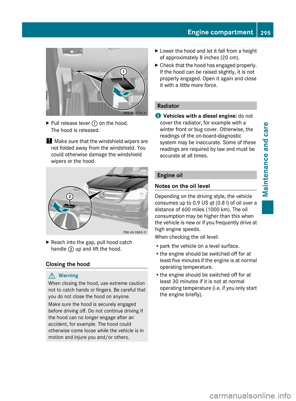
XPull release lever : on the hood.
The hood is released.
! Make sure that the windshield wipers are
not folded away from the windshield. You
could otherwise damage the windshield
wipers or the hood.
XReach into the gap, pull hood catch
handle ; up and lift the hood.
Closing the hood
GWarning
When closing the hood, use extreme caution
not to catch hands or fingers. Be careful that
you do not close the hood on anyone.
Make sure the hood is securely engaged
before driving off. Do not continue driving if
the hood can no longer engage after an
accident, for example. The hood could
otherwise come loose while the vehicle is in
motion and injure you and/or others.
XLower the hood and let it fall from a height
of approximately 8 inches (20 cm).XCheck that the hood has engaged properly.
If the hood can be raised slightly, it is not
properly engaged. Open it again and close
it with a little more force.
Radiator
i Vehicles with a diesel engine: do not
cover the radiator, for example with a
winter front or bug cover. Otherwise, the
readings of the on-board-diagnostic
system may be inaccurate. Some of these
readings are required by law and must be
accurate at all times.
Engine oil
Notes on the oil level
Depending on the driving style, the vehicle
consumes up to 0.9 US qt (0.8 l) of oil over a
distance of 600 miles (1000 km). The oil
consumption may be higher than this when
the vehicle is new or if you frequently drive at
high engine speeds.
When checking the oil level:
R park the vehicle on a level surface.
R the engine should be switched off for at
least five minutes if the engine is at normal
operating temperature.
R the engine should be switched off for at
least 30 minutes if it is not at normal
operating temperature (i.e. if you only start
the engine briefly).
Engine compartment295Maintenance and careBA 164.8 USA, CA Edition B 2011; 1; 2, en-USd2sboikeVersion: 3.0.3.52010-04-21T15:08:44+02:00 - Seite 295Z
Page 320 of 376
XOn downhill gradients: place chocks or
other suitable items in front of the wheels
of the front and rear axle.
Raising the vehicle
GWarning
When jacking up the vehicle, only use the jack
which has been specifically approved by
Mercedes-Benz for your vehicle.
The jack is designed exclusively for jacking up
the vehicle at the jacking points built into both
sides of the vehicle. The jack saddle must be
placed centrally under the jacking point. The
jack must always be vertical when in use,
especially on inclines or declines.
The jack is intended only for lifting the vehicle
briefly for wheel changes. It is not suited for
performing maintenance work under the
vehicle. To help avoid personal injury, use the
jack only to lift the vehicle during a wheel
change.
Never get beneath the vehicle while it is
supported by the jack. Keep hands and feet
away from the area under the lifted vehicle.
Always lower the vehicle onto sufficient
capacity jackstands before working under the
vehicle.
Always firmly engage the parking brake and
block the wheels with wheel chocks or other
sizable objects before raising the vehicle with
the jack. Do not disengage the parking brake
while the vehicle is raised.
Make sure that the ground on which the
vehicle is standing and where you place the
jack is solid, level and not slippery. If
necessary, use a large underlay. On slippery
surfaces, such as tiled floors, you should use
a non-slip underlay, for example a rubber mat.
Do not use wooden blocks or similar objects
as a jack underlay. Otherwise, the jack may
not be able to achieve its load-bearing
capacity if it is not at its full height.
Never start the engine when the vehicle is
raised.
Also observe the notes on the jack.
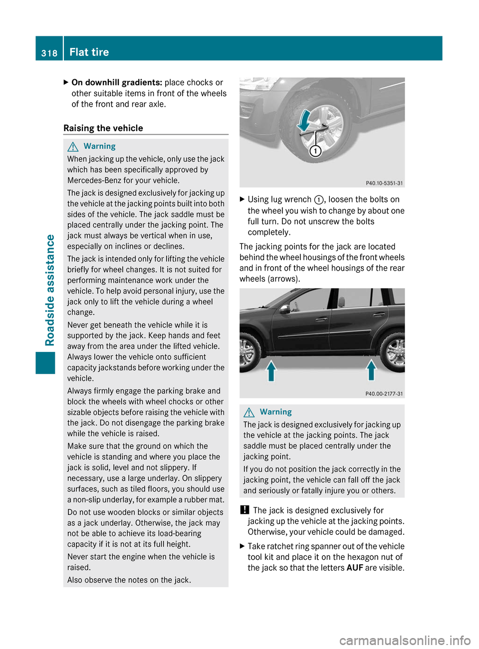
XUsing lug wrench :, loosen the bolts on
the wheel you wish to change by about one
full turn. Do not unscrew the bolts
completely.
The jacking points for the jack are located
behind the wheel housings of the front wheels
and in front of the wheel housings of the rear
wheels (arrows).
GWarning
The jack is designed exclusively for jacking up
the vehicle at the jacking points. The jack
saddle must be placed centrally under the
jacking point.
If you do not position the jack correctly in the
jacking point, the vehicle can fall off the jack
and seriously or fatally injure you or others.
! The jack is designed exclusively for
jacking up the vehicle at the jacking points.
Otherwise, your vehicle could be damaged.
XTake ratchet ring spanner out of the vehicle
tool kit and place it on the hexagon nut of
the jack so that the letters AUF are visible.318Flat tireRoadside assistance
BA 164.8 USA, CA Edition B 2011; 1; 2, en-USd2sboikeVersion: 3.0.3.52010-04-21T15:08:44+02:00 - Seite 318
Page 353 of 376
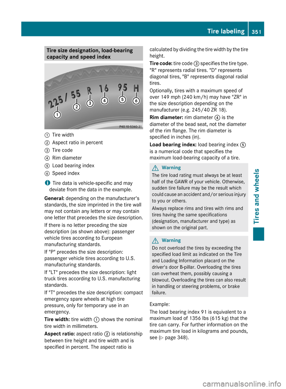
Tire size designation, load-bearing
capacity and speed index:Tire width;Aspect ratio in percent=Tire code?Rim diameterALoad bearing indexBSpeed index
i Tire data is vehicle-specific and may
deviate from the data in the example.
General: depending on the manufacturer's
standards, the size imprinted in the tire wall
may not contain any letters or may contain
one letter that precedes the size description.
If there is no letter preceding the size
description (as shown above): passenger
vehicle tires according to European
manufacturing standards.
If "P" precedes the size description:
passenger vehicle tires according to U.S.
manufacturing standards.
If "LT" precedes the size description: light
truck tires according to U.S. manufacturing
standards.
If "T" precedes the size description: compact
emergency spare wheels at high tire
pressure, only for temporary use in an
emergency.
Tire width: tire width : shows the nominal
tire width in millimeters.
Aspect ratio: aspect ratio ; is relationship
between tire height and tire width and is
specified in percent. The aspect ratio is
calculated by dividing the tire width by the tire
height.
Tire code: tire code = specifies the tire type.
"R" represents radial tires. "D" represents
diagonal tires, "B" represents diagonal radial
tires.
Optionally, tires with a maximum speed of
over 149 mph (240 km/h) may have "ZR" in
the size description depending on the
manufacturer (e.g. 245/40 ZR 18).
Rim diameter: rim diameter ? is the
diameter of the bead seat, not the diameter
of the rim flange. The rim diameter is
specified in inches (in).
Load bearing index: load bearing index A
is a numerical code that specifies the
maximum load-bearing capacity of a tire.GWarning
The tire load rating must always be at least
half of the GAWR of your vehicle. Otherwise,
sudden tire failure may be the result which
could cause an accident and/or serious injury
to you or others.
Always replace rims and tires with rims and
tires having the same specifications
(designation, manufacturer and type) as
shown on the original part.
GWarning
Do not overload the tires by exceeding the
specified load limit as indicated on the Tire
and Loading Information placard on the
driver's door B-pillar. Overloading the tires
can overheat them, possibly causing a
blowout. Overloading the tires can also result
in handling or steering problems, or brake
failure.
Example:
The load bearing index 91 is equivalent to a
maximum load of 1356 lbs (615 kg) that the
tire can carry. For further information on the
maximum tire load in kilograms and pounds,
see ( Y page 348).
Tire labeling351Tires and wheelsBA 164.8 USA, CA Edition B 2011; 1; 2, en-USd2sboikeVersion: 3.0.3.52010-04-21T15:08:44+02:00 - Seite 351Z