2011 MERCEDES-BENZ GL350 BlueTEC light
[x] Cancel search: lightPage 261 of 376
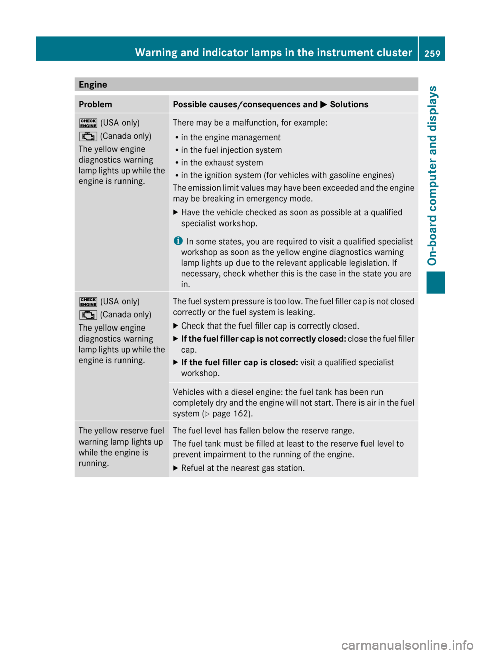
EngineProblemPossible causes/consequences and M Solutions! (USA only)
; (Canada only)
The yellow engine
diagnostics warning
lamp lights up while the
engine is running.There may be a malfunction, for example:
R in the engine management
R in the fuel injection system
R in the exhaust system
R in the ignition system (for vehicles with gasoline engines)
The emission limit values may have been exceeded and the engine
may be breaking in emergency mode.XHave the vehicle checked as soon as possible at a qualified
specialist workshop.
i In some states, you are required to visit a qualified specialist
workshop as soon as the yellow engine diagnostics warning
lamp lights up due to the relevant applicable legislation. If
necessary, check whether this is the case in the state you are
in.
! (USA only)
; (Canada only)
The yellow engine
diagnostics warning
lamp lights up while the
engine is running.The fuel system pressure is too low. The fuel filler cap is not closed
correctly or the fuel system is leaking.XCheck that the fuel filler cap is correctly closed.XIf the fuel filler cap is not correctly closed: close the fuel filler
cap.XIf the fuel filler cap is closed: visit a qualified specialist
workshop.Vehicles with a diesel engine: the fuel tank has been run
completely dry and the engine will not start. There is air in the fuel
system ( Y page 162).The yellow reserve fuel
warning lamp lights up
while the engine is
running.The fuel level has fallen below the reserve range.
The fuel tank must be filled at least to the reserve fuel level to
prevent impairment to the running of the engine.XRefuel at the nearest gas station.Warning and indicator lamps in the instrument cluster259On-board computer and displaysBA 164.8 USA, CA Edition B 2011; 1; 2, en-USd2sboikeVersion: 3.0.3.52010-04-21T15:08:44+02:00 - Seite 259Z
Page 262 of 376

Driving systemsProblemPossible causes/consequences and M Solutions·
The red DTR distance
warning lamp lights up
while the vehicle is in
motion. A warning tone
also sounds.GRisk of accident
A warning is issued if:
R you are approaching a vehicle in front at too great a speed
R DISTRONIC has detected a stationary obstacle in your line of
travel
XBe prepared to brake immediately.XPay careful attention to the traffic situation. You may have to
brake or take evasive action.
Tires
ProblemPossible causes/consequences and M Solutionsh
USA only:
The yellow combination
low tire pressure
telltale/TPMS
malfunction telltale for
the TPMS is on.GRisk of accident
The TPMS has detected a loss of pressure in at least one of the
tires.
XStop the vehicle without making any sudden steering or braking
maneuvers. Pay attention to the traffic conditions as you do so.XObserve the additional display messages in the multifunction
display.XCheck the tire pressure. If necessary, correct the tire pressure
( Y page 341).XIf necessary, change a wheel ( Y page 350).h
USA only:
The yellow combination
low tire pressure
telltale/TPMS
malfunction telltale for
the TPMS flashes for 60
seconds and then
remains illuminated.The TPMS is faulty.XObserve the additional display messages in the multifunction
display.XVisit a qualified specialist workshop.GWarning
Each tire, including the spare (if provided), should be checked every other week when cold and
inflated to the inflation pressure recommended by the vehicle manufacturer on the Tire and
Loading Information placard on the driver's door B-pillar or, if available, the tire inflation pressure
label on the inside of the fuel filler flap. If your vehicle has tires of a different size than the size
260Warning and indicator lamps in the instrument clusterOn-board computer and displays
BA 164.8 USA, CA Edition B 2011; 1; 2, en-USd2sboikeVersion: 3.0.3.52010-04-21T15:08:44+02:00 - Seite 260
Page 268 of 376
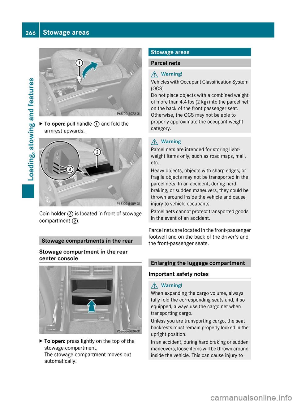
XTo open: pull handle : and fold the
armrest upwards.
Coin holder = is located in front of stowage
compartment ;.
Stowage compartments in the rear
Stowage compartment in the rear
center console
XTo open: press lightly on the top of the
stowage compartment.
The stowage compartment moves out
automatically.Stowage areas
Parcel nets
GWarning!
Vehicles with Occupant Classification System
(OCS)
Do not place objects with a combined weight
of more than 4.4 lbs (2 kg) into the parcel net
on the back of the front passenger seat.
Otherwise, the OCS may not be able to
properly approximate the occupant weight
category.
GWarning
Parcel nets are intended for storing light-
weight items only, such as road maps, mail,
etc.
Heavy objects, objects with sharp edges, or
fragile objects may not be transported in the
parcel nets. In an accident, during hard
braking, or sudden maneuvers, they could be
thrown around inside the vehicle and cause
injury to vehicle occupants.
Parcel nets cannot protect transported goods
in the event of an accident.
Parcel nets are located in the front-passenger
footwell and on the back of the driver's and
the front-passenger seats.
Enlarging the luggage compartment
Important safety notes
GWarning!
When expanding the cargo volume, always
fully fold the corresponding seats and, if so
equipped, always use the cargo net when
transporting cargo.
Unless you are transporting cargo, the seat
backrests must remain properly locked in the
upright position.
In an accident, during hard braking or sudden
maneuvers, loose items will be thrown around
inside the vehicle. This can cause injury to
266Stowage areasLoading, stowing and features
BA 164.8 USA, CA Edition B 2011; 1; 2, en-USd2sboikeVersion: 3.0.3.52010-04-21T15:08:44+02:00 - Seite 266
Page 270 of 376
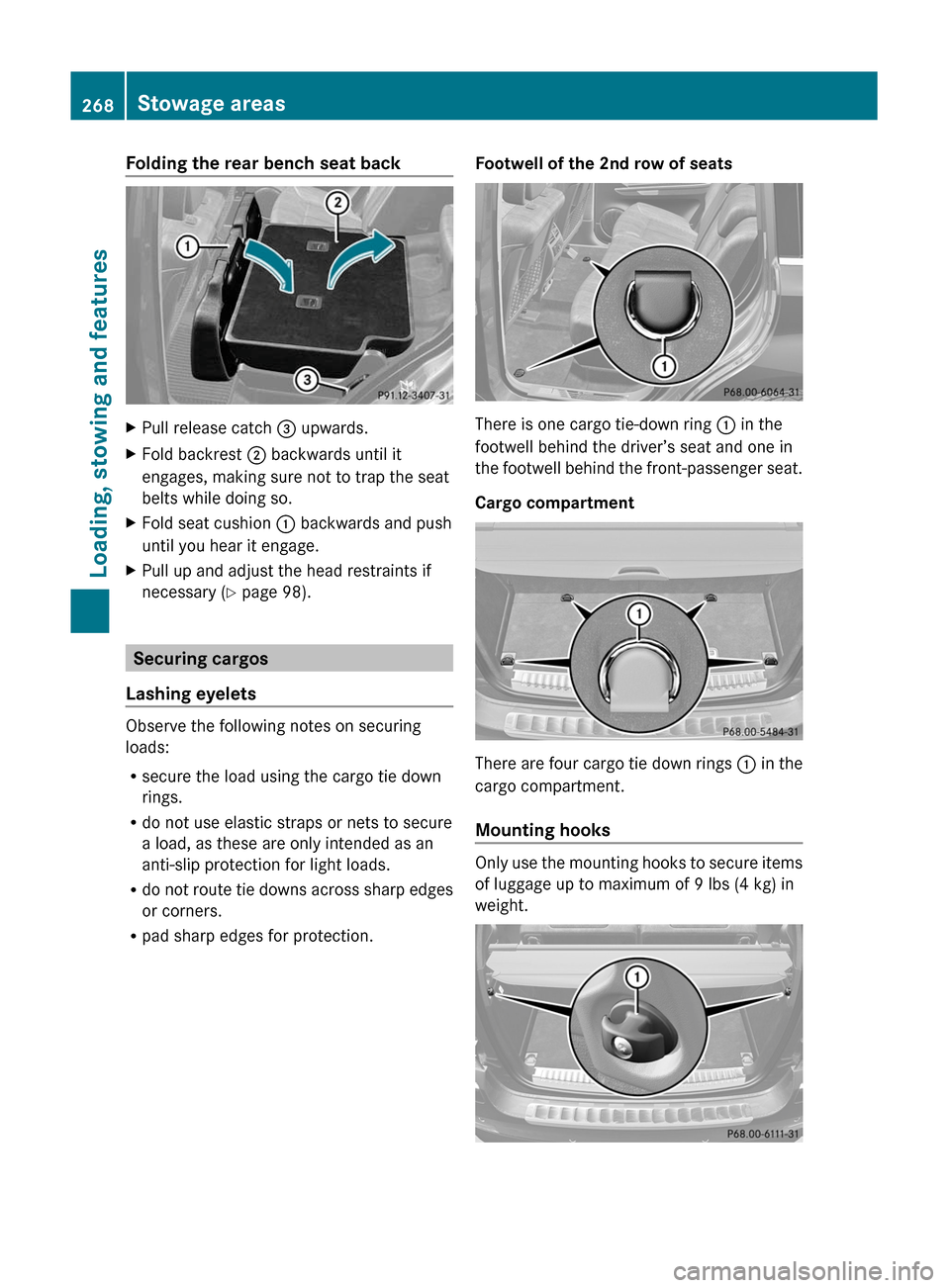
Folding the rear bench seat backXPull release catch = upwards.XFold backrest ; backwards until it
engages, making sure not to trap the seat
belts while doing so.XFold seat cushion : backwards and push
until you hear it engage.XPull up and adjust the head restraints if
necessary ( Y page 98).
Securing cargos
Lashing eyelets
Observe the following notes on securing
loads:
R secure the load using the cargo tie down
rings.
R do not use elastic straps or nets to secure
a load, as these are only intended as an
anti-slip protection for light loads.
R do not route tie downs across sharp edges
or corners.
R pad sharp edges for protection.
Footwell of the 2nd row of seats
There is one cargo tie-down ring : in the
footwell behind the driver’s seat and one in
the footwell behind the front-passenger seat.
Cargo compartment
There are four cargo tie down rings : in the
cargo compartment.
Mounting hooks
Only use the mounting hooks to secure items
of luggage up to maximum of 9 lbs (4 kg) in
weight.
268Stowage areasLoading, stowing and features
BA 164.8 USA, CA Edition B 2011; 1; 2, en-USd2sboikeVersion: 3.0.3.52010-04-21T15:08:44+02:00 - Seite 268
Page 274 of 376
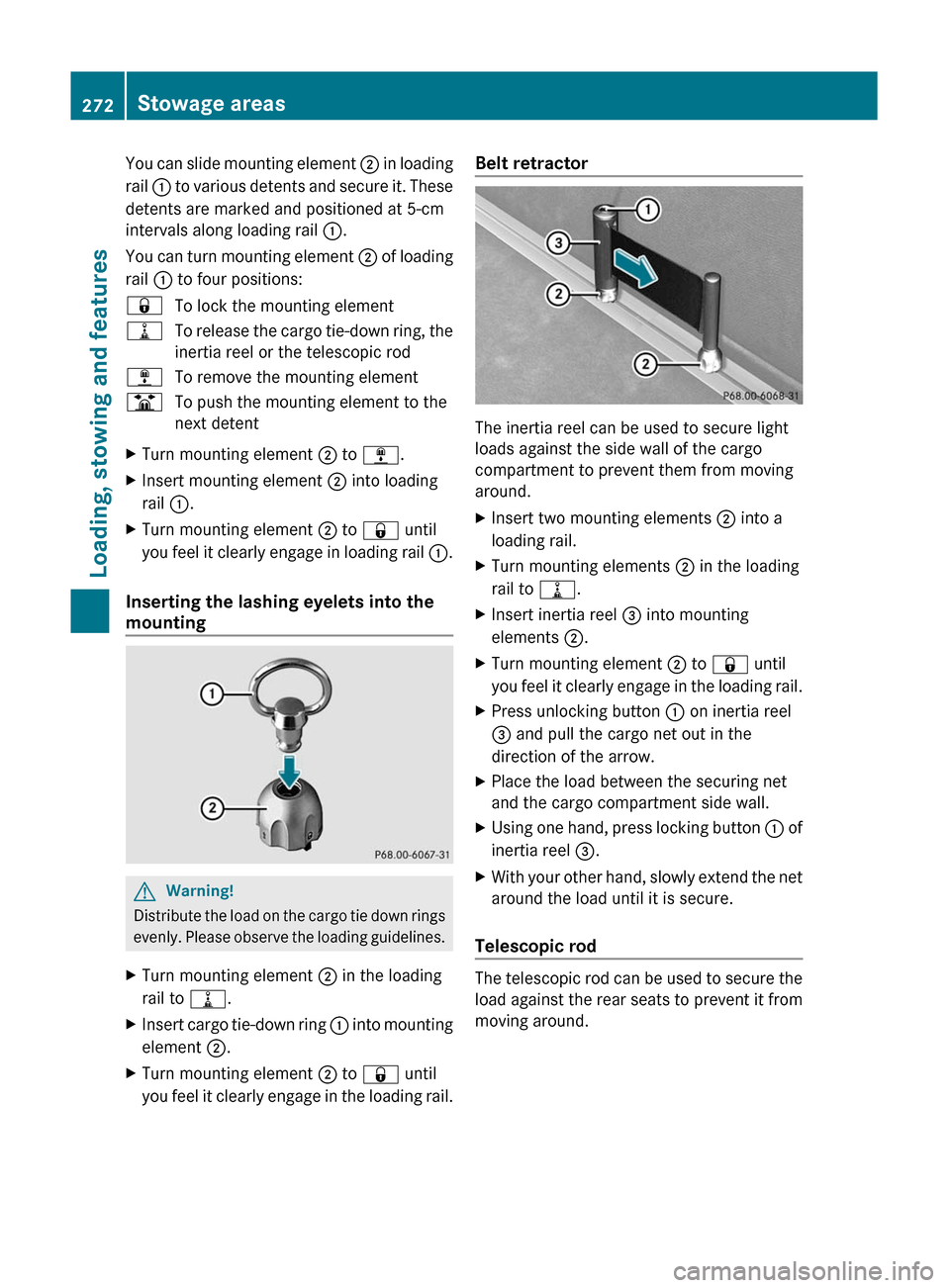
You can slide mounting element ; in loading
rail : to various detents and secure it. These
detents are marked and positioned at 5-cm
intervals along loading rail :.
You can turn mounting element ; of loading
rail : to four positions:&To lock the mounting element=To release the cargo tie-down ring, the
inertia reel or the telescopic rod;To remove the mounting elementBTo push the mounting element to the
next detentXTurn mounting element ; to ; .XInsert mounting element ; into loading
rail :.XTurn mounting element ; to & until
you feel it clearly engage in loading rail :.
Inserting the lashing eyelets into the
mounting
GWarning!
Distribute the load on the cargo tie down rings
evenly. Please observe the loading guidelines.
XTurn mounting element ; in the loading
rail to =.XInsert cargo tie-down ring : into mounting
element ;.XTurn mounting element ; to & until
you feel it clearly engage in the loading rail.Belt retractor
The inertia reel can be used to secure light
loads against the side wall of the cargo
compartment to prevent them from moving
around.
XInsert two mounting elements ; into a
loading rail.XTurn mounting elements ; in the loading
rail to =.XInsert inertia reel = into mounting
elements ;.XTurn mounting element ; to & until
you feel it clearly engage in the loading rail.XPress unlocking button : on inertia reel
= and pull the cargo net out in the
direction of the arrow.XPlace the load between the securing net
and the cargo compartment side wall.XUsing one hand, press locking button : of
inertia reel =.XWith your other hand, slowly extend the net
around the load until it is secure.
Telescopic rod
The telescopic rod can be used to secure the
load against the rear seats to prevent it from
moving around.
272Stowage areasLoading, stowing and features
BA 164.8 USA, CA Edition B 2011; 1; 2, en-USd2sboikeVersion: 3.0.3.52010-04-21T15:08:44+02:00 - Seite 272
Page 277 of 376
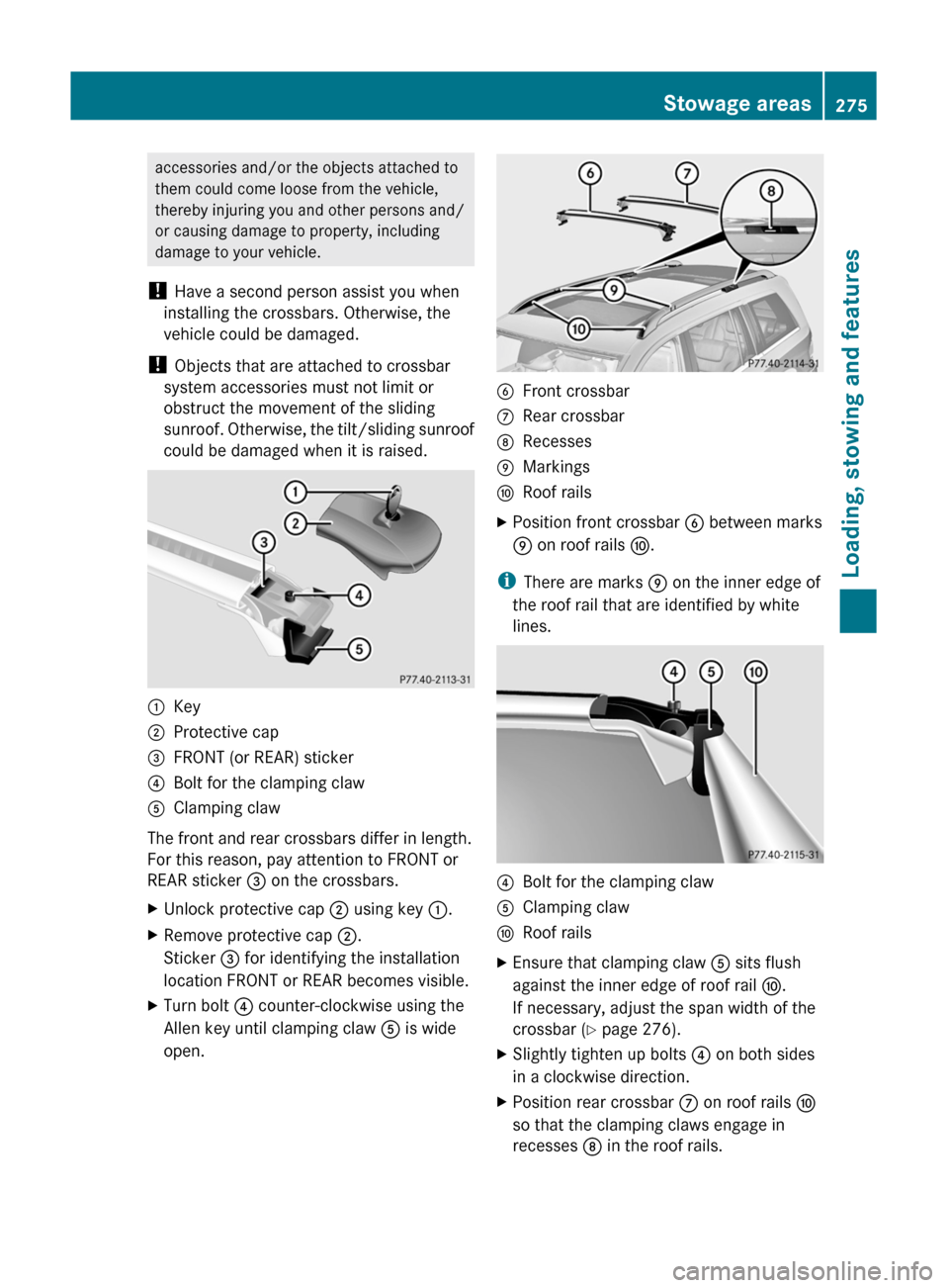
accessories and/or the objects attached to
them could come loose from the vehicle,
thereby injuring you and other persons and/
or causing damage to property, including
damage to your vehicle.
! Have a second person assist you when
installing the crossbars. Otherwise, the
vehicle could be damaged.
! Objects that are attached to crossbar
system accessories must not limit or
obstruct the movement of the sliding
sunroof. Otherwise, the tilt/sliding sunroof
could be damaged when it is raised.:Key;Protective cap=FRONT (or REAR) sticker?Bolt for the clamping clawAClamping claw
The front and rear crossbars differ in length.
For this reason, pay attention to FRONT or
REAR sticker = on the crossbars.
XUnlock protective cap ; using key :.XRemove protective cap ;.
Sticker = for identifying the installation
location FRONT or REAR becomes visible.XTurn bolt ? counter-clockwise using the
Allen key until clamping claw A is wide
open.BFront crossbarCRear crossbarDRecessesEMarkingsFRoof railsXPosition front crossbar B between marks
E on roof rails F.
i
There are marks E on the inner edge of
the roof rail that are identified by white
lines.
?Bolt for the clamping clawAClamping clawFRoof railsXEnsure that clamping claw A sits flush
against the inner edge of roof rail F.
If necessary, adjust the span width of the
crossbar ( Y page 276).XSlightly tighten up bolts ? on both sides
in a clockwise direction.XPosition rear crossbar C on roof rails F
so that the clamping claws engage in
recesses D in the roof rails.Stowage areas275Loading, stowing and featuresBA 164.8 USA, CA Edition B 2011; 1; 2, en-USd2sboikeVersion: 3.0.3.52010-04-21T15:08:44+02:00 - Seite 275Z
Page 278 of 376

XEnsure that clamping claw A sits flush
against the inner edge of roof rail F.
If necessary, adjust the span width of the
crossbar ( Y page 276).XSlightly tighten up bolts ? on both sides
in a clockwise direction.XTighten up bolts ? on the front and rear
crossbars. Observe the tightening torque of
4 lb/ft (6 Nm) .GWarning!
Have the tightening torque checked after
mounting the crossbars. The screws could
come loose if they are not tightened to a
torque of 4 lb-ft (6 Nm).
XAttach and lock protective caps ;.XStow the key and Allen key in the stowage
compartment under the cargo
compartment floor again ( Y page 274).
Setting the span width of the crossbars
GWarning!
Only install the crossbars at the exact
locations designated on the roof rails. The
designated locations for the front crossbars
are between the markings engraved on the
inside of the roof rails. The designated
locations for the rear crossbars are between
the gaps on the roof rails.
Otherwise, the crossbars, mounted
accessories and the objects attached to them
could come loose from the vehicle causing an
accident, thereby injuring you and other
persons and/or causing damage to property,
including damage to your vehicle.
The span width of the crossbars for your
vehicle is set at the factory. The span widths
only fit in the intended positions on the
vehicle.
Only install the crossbars at the marked
positions and observe stickers = FRONT and
REAR.
?Bolt for the clamping clawAClamping clawGBolts for adjusting the span width (2 per
side)HCover stripXPull cover strip H out of the groove until
bolts G on both ends of the crossbar are
visible.XTurn bolts G on both sides approximately
two turns counterclockwise.XAlign the crossbars on the marked
positions on the roof rails.XEnsure that clamping claws A sit flush
with the roof rails on both sides. If
necessary, pull out or slide into clamping
claws A.XTighten bolts G. Observe the tightening
torque of 4 lb/ft (6 Nm) .
The width of the clamping claw is not set
correctly.GWarning!
Have the tightening torque checked after
mounting the crossbars. The screws could
come loose if they are not tightened to a
torque of 4 lb-ft (6 Nm).
XPress cover strip H piece by piece into the
groove of the crossbar.XInstall the crossbars as described
( Y page 274).276Stowage areasLoading, stowing and features
BA 164.8 USA, CA Edition B 2011; 1; 2, en-USd2sboikeVersion: 3.0.3.52010-04-21T15:08:44+02:00 - Seite 276
Page 280 of 376
You can remove the cup holder to clean it.
Clean the cup holder with clear, lukewarm
water only.XTo remove: hold cup holder : by
support ; and pull out in the direction of
the arrow.XTo install: place the cup holder into the
guides and insert.
Cup holder in the rear seat armrest
! Do not sit or lean your bodyweight on the
armrests when they are folded out as you
could damage them.
XFold down the armrest.
Cup holder in the third row of seats
The cup holders are located in the side trim
on the left and right-hand sides.
Sun visors
GWarning
Do not use the vanity mirror while driving.
Keep the vanity mirrors in the sun visors
closed while the vehicle is in motion.
Reflected glare can endanger you and others.
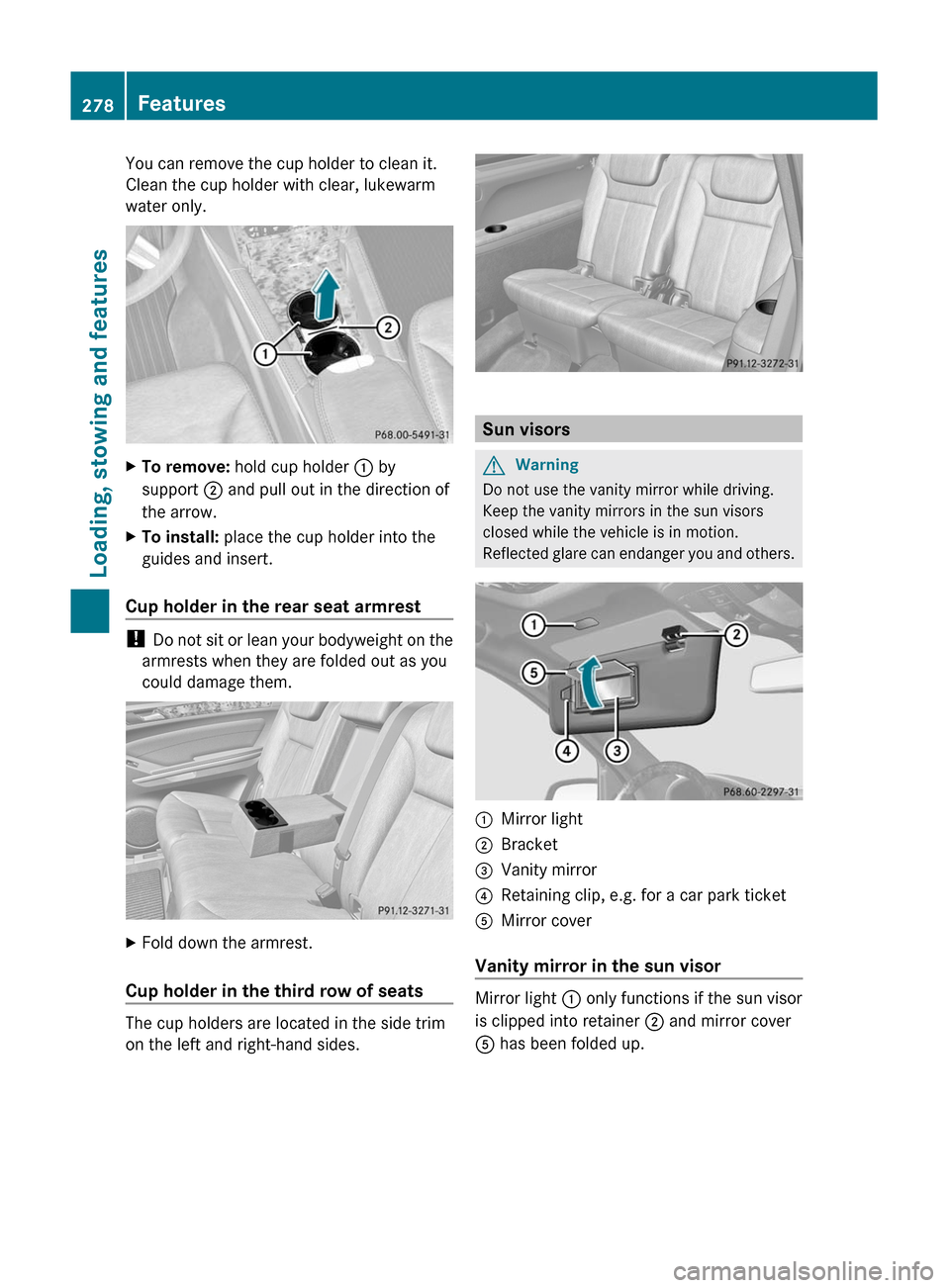
:Mirror light;Bracket=Vanity mirror?Retaining clip, e.g. for a car park ticketAMirror cover
Vanity mirror in the sun visor
Mirror light : only functions if the sun visor
is clipped into retainer ; and mirror cover
A has been folded up.
278FeaturesLoading, stowing and features
BA 164.8 USA, CA Edition B 2011; 1; 2, en-USd2sboikeVersion: 3.0.3.52010-04-21T15:08:44+02:00 - Seite 278