2011 MERCEDES-BENZ GL trunk
[x] Cancel search: trunkPage 19 of 376

Unladen weight (definition) ............355
Wear indicator (definition) .............356
Wheel rim (definition) ....................355
Tires and wheels (important safety
information) ....................................... 334
Top Tether ............................................ 62
Towing Important safety guidelines ...........327
Towing a trailer
Driving tips .................................... 209
Towing away
Installing the towing eye ................327
Removing the towing eye ...............328
Trailer
Coupling up ................................... 209
Decoupling ..................................... 211
Display message ............................ 237
Power supply ................................. 212
Towing ........................................... 210
Trailer loads and drawbar
noseweights ...................................... 211
Trailer towing .................................... 155
Blind Spot Assist ............................ 202
ESP ®
................................................ 68
PARKTRONIC ................................. 197
Transfer case ..................................... 157
Shift ranges ................................... 158
Transmission position display ......... 153
Transmission positions .................... 154
Traveling uphill Brow of hill ..................................... 178
Driving downhill ............................. 178
Maximum gradient-climbing
capability ....................................... 178
Trip computer (on-board
computer) .......................................... 227
Trip odometer Calling up ....................................... 218
Resetting (on-board computer) ......227
Trunk
Automatic opening ..................... 82, 83
Turn signal (display message) ......... 237
Turn signals ....................................... 117
TWR (permissible trailer drawbar
noseweight) (definition) ................... 356
Type plate
see Vehicle identification plate U
Unlocking Emergency unlocking .......................80
From inside the vehicle (central
unlocking button) ............................. 79
V
Vanity mirror Sun visor ........................................ 278
Vehicle
Data acquisition ............................... 23
Emergency release ..........................80
Equipment ....................................... 19
Exterior view .................................... 26
Individual settings (on-board
computer) ...................................... 221
Loading .......................................... 344
Lowering ........................................ 320
Maintenance .................................... 20
Parking up ..................................... 166
Raising ........................................... 318
Reporting problems .........................22
Towing away .................................. 327
Tow-starting ................................... 327
Transporting .................................. 329
Vehicle data
see Technical data
Vehicle identification number
see VIN
Vehicle identification plate .............. 363
Vehicle tool kit .................................. 310
Video (DVD) ........................................ 220
Video DVD (on-board computer) ...... 220
VIN ...................................................... 363
W
Warning and indicator lamps Overview .......................................... 29
PASSENGER AIRBAG OFF
indicator lamp (only Canada) ...........48
PASSENGER AIRBAG OFF
indicator lamp (only USA) ................42
Warranty ............................................ 362
Wheel bolt tightening torque ........... 320
Wheel chock ...................................... 317
Index17BA 164.8 USA, CA Edition B 2011; 1; 2, en-USd2sboikeVersion: 3.0.3.52010-04-21T15:08:44+02:00 - Seite 17
Page 61 of 376
Children in the vehicle
Important safety notes
GWarning
When leaving the vehicle, always remove the
SmartKey from the ignition lock. Always take
the SmartKey with you and lock the vehicle.
Do not leave children unattended in the
vehicle, even if they are secured in a child
restraint system, or with access to an
unlocked vehicle. A child's unsupervised
access to a vehicle could result in an accident
and/or serious personal injury. The children
could:
R injure themselves on parts of the vehicle
R be seriously or fatally injured through
excessive exposure to extreme heat or cold
R injure themselves or cause an accident with
vehicle equipment that can be operated
even if the SmartKey is removed from the
ignition lock or removed from the vehicle,
such as seat adjustment, steering wheel
adjustment, or the memory function
If children open a door, they could injure other
persons or get out of the vehicle and injure
themselves or be injured by following traffic.
Do not expose the child restraint system to
direct sunlight. The child restraint system's
metal parts, for example, could become very
hot, and the child could be burned on these
parts.
GWarning!
Do not carry heavy or hard objects in the
passenger compartment or trunk unless they
are firmly secured in place.
Unsecured or improperly positioned cargo
increases a child's risk of injury in the event
of
R strong braking maneuvers
R sudden changes of direction
R an accident
If an infant or child is traveling in the vehicle:XSecure the child using an infant or child
restraint system appropriate to the age and
weight of the child.XMake sure that the infant or child is
properly secured at all times while the
vehicle is in motion.
Child restraint systems
Important safety notes
GWarning
Observe "Important safety instructions"
( Y page 59).
We recommend all infants and children be
properly restrained using the child restraint
systems at all times while the vehicle is in
motion.
The use of infant or child restraints is required
by law in all 50 states, the District of
Columbia, the U.S. territories and all
Canadian provinces.
Infants and small children should always be
seated in an infant or child seat restraint
system appropriate for the size and weight of
the child. They must be properly secured in
accordance with the manufacturer's
installation instructions for the infant or child
seat restraint system. All infant and child seat
restraint systems must comply with the US
Federal Motor Vehicle Safety Standards 213
and 225 and Canadian Motor Vehicle Safety
Standards 213 and 210.2.
A statement by the child restraint
manufacturer of compliance with these
standards can be found on the instruction
label on the child restraint system. You will
also find the statement in the instruction
manual provided with the child restraint
system.
When using an infant restraint system, child
restraint system or booster seat, make sure
to carefully read and follow all manufacturer's
instructions for installation and use.
Children in the vehicle59SafetyBA 164.8 USA, CA Edition B 2011; 1; 2, en-USd2sboikeVersion: 3.0.3.52010-04-21T15:08:44+02:00 - Seite 59Z
Page 65 of 376
that rear seat backrests are secured properly
by pushing and pulling on the seat backrests.
If the seat backrest is not locked properly, the
seat backrest could fold forward. The child
restraint system is no longer supported
properly or held in position and can no longer
fulfill its function. That could cause serious or
even fatal injuries.
Top Tether provides an additional connection
between the child restraint system secured
with ISOFIX and the rear seat. It helps reduce
the risk of injury even further.
The Top Tether anchorages in the second row
of seats are located on the rear of the rear
seat backrests. For the third row of seats, use
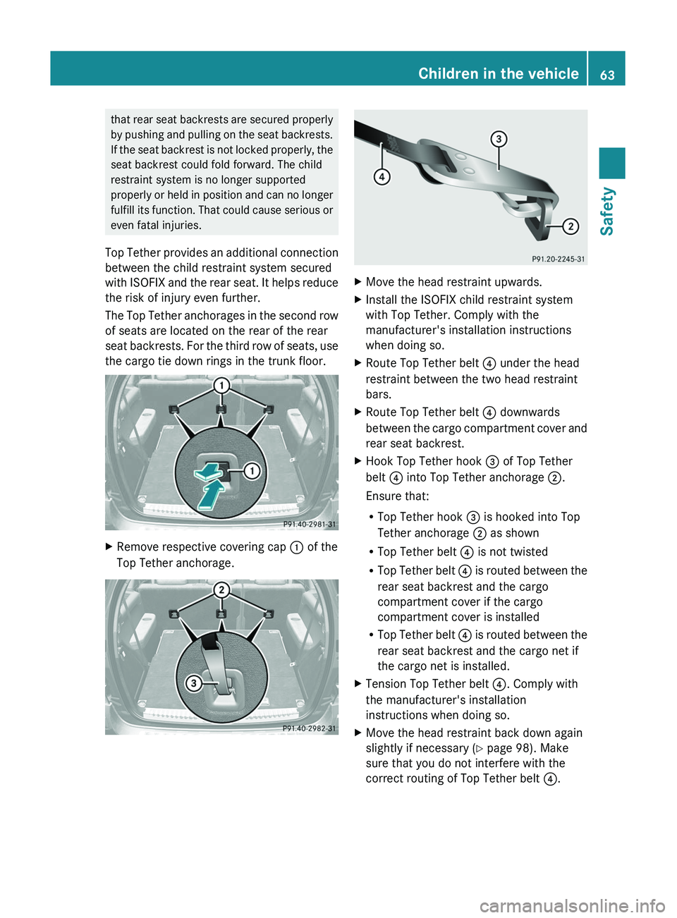
the cargo tie down rings in the trunk floor.XRemove respective covering cap : of the
Top Tether anchorage.XMove the head restraint upwards.XInstall the ISOFIX child restraint system
with Top Tether. Comply with the
manufacturer's installation instructions
when doing so.XRoute Top Tether belt ? under the head
restraint between the two head restraint
bars.XRoute Top Tether belt ? downwards
between the cargo compartment cover and
rear seat backrest.XHook Top Tether hook = of Top Tether
belt ? into Top Tether anchorage ;.
Ensure that:
R Top Tether hook = is hooked into Top
Tether anchorage ; as shown
R Top Tether belt ? is not twisted
R Top Tether belt ? is routed between the
rear seat backrest and the cargo
compartment cover if the cargo
compartment cover is installed
R Top Tether belt ? is routed between the
rear seat backrest and the cargo net if
the cargo net is installed.XTension Top Tether belt ?. Comply with
the manufacturer's installation
instructions when doing so.XMove the head restraint back down again
slightly if necessary ( Y page 98). Make
sure that you do not interfere with the
correct routing of Top Tether belt ?.Children in the vehicle63SafetyBA 164.8 USA, CA Edition B 2011; 1; 2, en-USd2sboikeVersion: 3.0.3.52010-04-21T15:08:44+02:00 - Seite 63Z
Page 72 of 376

The alarm is not switched off, even if you
close the open door that has triggered it, for
example.
i If the alarm stays on for more than 30
seconds, the emergency call system
mbrace (USA only) or Tele Aid (Canada
only) initiates a call to the Customer
Assistance Center automatically. The
emergency call system initiates the call
provided that:
R you have subscribed to the mbrace/Tele
Aid service
R the mbrace/Tele Aid service has been
activated properly
R the mobile phone, power supply and GPS
necessary are availableXTo arm: lock the vehicle with the SmartKey
or KEYLESS-GO.
The turn signal lamps flash three times to
indicate that the vehicle is locked. Indicator
lamp : flashes to indicate that the alarm
system is armed.
i If the turn signal lamps do not flash three
times, a door or the tailgate may not be
properly closed.
It may be necessary to close the affected
door or the tailgate.
XTo deactivate: unlock the vehicle using the
key or KEYLESS-GO.
The turn signal lamps flash once to indicate
that the anti-theft alarm system is switched
off.i Unless you open a door or the trunk lid
within 40 seconds after unlocking the
vehicle:
R the vehicle will be locked again.
R the anti-theft alarm system will be re-
armed.XTo stop the alarm using the SmartKey:
insert the key into the ignition lock.
The alarm is switched off.
or
XPress the % or & button on the key.
The alarm is switched off.XTo stop the alarm using KEYLESS-GO:
grasp the outside door handle. The key
must be outside the vehicle.
The alarm is switched off.
or
XPress the Start/Stop button on the
dashboard. The key must be inside the
vehicle.
The alarm is switched off.70Anti-theft systemsSafety
BA 164.8 USA, CA Edition B 2011; 1; 2, en-USd2sboikeVersion: 3.0.3.52010-04-21T15:08:44+02:00 - Seite 70
Page 273 of 376
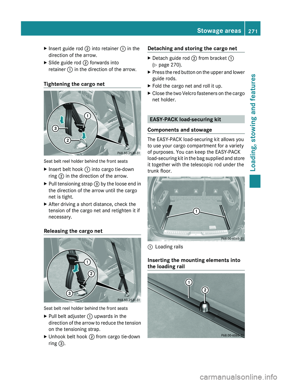
XInsert guide rod ; into retainer : in the
direction of the arrow.XSlide guide rod ; forwards into
retainer : in the direction of the arrow.
Tightening the cargo net
Seat belt reel holder behind the front seats
XInsert belt hook : into cargo tie-down
ring ; in the direction of the arrow.XPull tensioning strap = by the loose end in
the direction of the arrow until the cargo
net is tight.XAfter driving a short distance, check the
tension of the cargo net and retighten it if
necessary.
Releasing the cargo net
Seat belt reel holder behind the front seats
XPull belt adjuster : upwards in the
direction of the arrow to reduce the tension
on the tensioning strap.XUnhook belt hook ; from cargo tie-down
ring =.Detaching and storing the cargo netXDetach guide rod ; from bracket :
( Y page 270).XPress the red button on the upper and lower
guide rods.XFold the cargo net and roll it up.XClose the two Velcro fasteners on the cargo
net holder.
EASY-PACK load-securing kit
Components and stowage
The EASY-PACK load-securing kit allows you
to use your cargo compartment for a variety
of purposes. You can keep the EASY-PACK
load-securing kit in the bag supplied and store
it together with the telescopic rod under the
trunk floor.
:Loading rails
Inserting the mounting elements into
the loading rail
Stowage areas271Loading, stowing and featuresBA 164.8 USA, CA Edition B 2011; 1; 2, en-USd2sboikeVersion: 3.0.3.52010-04-21T15:08:44+02:00 - Seite 271Z
Page 313 of 376
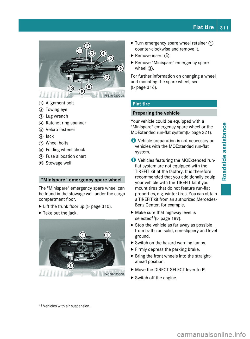
:Alignment bolt;Towing eye=Lug wrench?Ratchet ring spannerAVelcro fastenerBJackCWheel boltsDFolding wheel chockEFuse allocation chartFStowage well
"Minispare" emergency spare wheel
The "Minispare" emergency spare wheel can
be found in the stowage well under the cargo
compartment floor.
XLift the trunk floor up ( Y page 310).XTake out the jack.XTurn emergency spare wheel retainer :
counter-clockwise and remove it.XRemove insert =.XRemove "Minispare" emergency spare
wheel ;.
For further information on changing a wheel
and mounting the spare wheel, see
( Y page 316).
Flat tire
Preparing the vehicle
Your vehicle could be equipped with a
"Minispare" emergency spare wheel or the
MOExtended run-flat system( Y page 321).
i Vehicle preparation is not necessary on
vehicles with the MOExtended run-flat
system.
i Vehicles featuring the MOExtended run-
flat system are not equipped with the
TIREFIT kit at the factory. It is therefore
recommended that you additionally equip
your vehicle with the TIREFIT kit if you
mount tires that do not feature run-flat
properties, e.g. winter tires. You can obtain
a TIREFIT kit from an authorized Mercedes-
Benz Center, for example.
XMake sure that highway level is
selected 41
(Y page 189).XStop the vehicle as far away as possible
from traffic on solid, non-slippery and level
ground.XSwitch on the hazard warning lamps.XFirmly depress the parking brake.XBring the front wheels into the straight-
ahead position.XMove the DIRECT SELECT lever to P.XSwitch off the engine.41
Vehicles with air suspension.Flat tire311Roadside assistanceBA 164.8 USA, CA Edition B 2011; 1; 2, en-USd2sboikeVersion: 3.0.3.52010-04-21T15:08:44+02:00 - Seite 311Z
Page 314 of 376
XVehicles without KEYLESS-GO: remove
the key from the ignition lock.
XVehicles with KEYLESS-GO: open the
driver's door.
The on-board electronics have status 0,
which is the same as the key having been
removed.
XVehicles with KEYLESS-GO: remove the
Start/Stop button from the ignition lock
(Y page 147).
XAll occupants must get out of the vehicle.
Make sure that they are not endangered as
they get out of the vehicle.
XMake sure that no one is near the danger
area whilst a wheel is being changed.
Anyone who is not directly assisting in the
wheel change should, for example, stand
behind the barrier.
XGet out of the vehicle. Pay attention to
traffic conditions when doing so.
XClose the driver's door.
iOnly operate the electric air pump using
the socket in the footwell of the 2nd row of
seats (Y page 281), even if the ignition is
turned off.
An emergency cut-off ensures that the on-
board voltage does not drop too low. If the
on-board voltage is too low, power to the
sockets is automatically cut-off. This
ensures that there is sufficient power to
start the engine.
TIREFIT kit
Using the TIREFIT kit
You can use the TIREFIT kit to seal small
punctures, particularly those in the tire tread.
You can use TIREFIT at outside temperatures
down to -4 ‡ (-20 †).
GWarning
TIREFIT is a limited repair device. TIREFIT
cannot be used for cuts or punctures larger
than approximately 0.16 in (4 mm) and tire
damage caused by driving with extremely low
tire inflation pressure, or on a flat tire, or a
damaged wheel.
Do not drive the vehicle under such
circumstances.
Contact the nearest authorized Mercedes-
Benz Center for assistance or call roadside
assistance.
XDo not remove any foreign objects which
have penetrated the tire, e.g. screws or
nails.
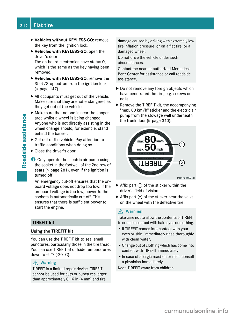
XRemove the TIREFIT kit, the accompanying
"max. 80 km/h" sticker and the electric air
pump from the stowage well underneath
the trunk floor (Y page 310).
XAffix part : of the sticker within the
driver's field of vision.
XAffix part ; of the sticker near the valve
on the wheel with the defective tire.
GWarning!
Take care not to allow the contents of TIREFIT
to come in contact with hair, eyes or clothing.
RIf TIREFIT comes into contact with your
eyes or skin, immediately rinse thoroughly
with clean water.
RChange out of clothing which has come into
contact with TIREFIT immediately.
RIn case of allergic reaction or rash, consult
a physician immediately.
Keep TIREFIT away from children.
312Flat tireRoadside assistance
BA 164.8 USA, CA Edition B 2011; 1; 2, en-USd2sboikeVersion: 3.0.3.52010-04-21T15:08:44+02:00 - Seite 312
Page 319 of 376
lug wrench, consult an authorized
Mercedes-Benz Center.
XPrepare the vehicle as described
(Y page 311).
XIf a trailer is coupled to the vehicle,
uncouple it.
XRemove the following items from the
stowage well under the trunk floor:
Rthe emergency spare wheel42
Rthe lug wrench
Rthe folding wheel chock
Rthe jack
Rthe ratchet ring spanner
Rthe alignment bolt
Rthe wheel bolts for the emergency spare
wheel
XSecure the vehicle to prevent it from rolling
away.
Securing the vehicle to prevent it from
rolling away
GWarning
Only jack up the vehicle on level ground or on
slight inclines/declines. The vehicle could
otherwise fall off the jack and injure you or
others.
If your vehicle is equipped with a wheel chock,
it can be found in the vehicle tool kit
(Y page 310).
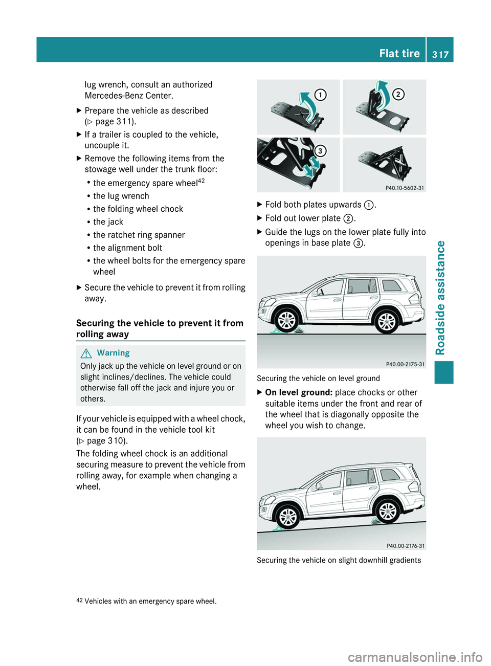
The folding wheel chock is an additional
securing measure to prevent the vehicle from
rolling away, for example when changing a
wheel.
XFold both plates upwards :.XFold out lower plate ;.XGuide the lugs on the lower plate fully into
openings in base plate =.
Securing the vehicle on level ground
XOn level ground: place chocks or other
suitable items under the front and rear of
the wheel that is diagonally opposite the
wheel you wish to change.
Securing the vehicle on slight downhill gradients
42Vehicles with an emergency spare wheel.Flat tire317Roadside assistanceBA 164.8 USA, CA Edition B 2011; 1; 2, en-USd2sboikeVersion: 3.0.3.52010-04-21T15:08:44+02:00 - Seite 317Z