2011 MERCEDES-BENZ E350 4MATIC Page 140
[x] Cancel search: Page 140Page 54 of 400

situations (on vehicles with DISTRONIC
PLUS)
R in critical driving situations, e.g. when
physical limits are exceeded and the
vehicle understeers or oversteers severely
or when having to swerve to avoid an
obstacle at a speed above 85 mph
(140 km/h).
PRE-SAFE ®
takes the following measures
depending on the hazardous situation
detected:
R the front seat belts are pre-tensioned.
R under accident conditions, the front-
passenger seat is adjusted if it is in an
unfavorable position.
R increases the air pressure in the side
bolsters of the seat cushion and seat
backrest of the active multicontour seats in
the front.
R if the vehicle skids, the sliding roof with
power tilt/sliding panel and the side
windows are closed so that only a small gap
remains.
If the hazardous situation passes without
resulting in an accident, PRE-SAFE ®
slackens
the belt pretensioning. The air pressure in the
side bolsters on the active multicontour seat
is reduced again. All settings made by PRE-
SAFE ®
can then be reversed.
If the seat belts are not released:XWhen the vehicle is stationary, move the
backrest or seat back slightly.
The belt pretensioning is reduced and the
locking mechanism is released.GWarning
Make sure that nobody can become trapped
as you adjust the seat.
! Make sure that there are no objects in the
footwell or behind the seats when resetting
the seats. There is a risk that the seats
and/or the objects could be damaged.
More information about belt adjustment, a
convenience function integrated into PRE-
SAFE ®
, can be found in the "Belt adjustment"
section ( Y page 56).
NECK-PRO head restraints
The NECK-PRO head restraints increase
protection for the driver's and front-
passenger's head and neck. In the event of a
rear collision of a certain severity, the NECK-
PRO head restraints on the driver's and front-
passenger seats are moved forwards and
upwards. This provides better head support.
GWarning
Do not secure any objects (e.g. coat hangers)
on the NECK-PRO head restraints. Otherwise,
the NECK-PRO head restraints may not
function properly, or in the event of a rear-end
collision may not be able offer the level of
protection they are designed to provide.
GWarning
Only use seat covers/head restraint covers
that have been tested and approved by
Mercedes-Benz for your model.
Using seat covers and head restraint covers
other than those recommended may cause a
malfunction when NECK-PRO head restraints
are triggered or front side impact air bags/
pelvis air bags may be prevented from
deploying.
Contact an authorized Mercedes-Benz Center
for availability.
If the NECK-PRO head restraints have been
triggered in an accident, you must reset the
NECK-PRO head restraints on the driver's and
front-passenger seat ( Y page 53).
Otherwise, the additional protection will not
be available in the event of another rear-end
collision. You can recognize that NECK-PRO
head restraints have been triggered by the
fact that they have moved forwards and can
no longer be adjusted.
52Occupant safetySafety
BA 212 USA, CA Edition B 2011; 1; 5, en-USdimargiVersion: 3.0.3.62010-05-20T13:33:46+02:00 - Seite 52
Page 142 of 400

3-zone automatic climate control
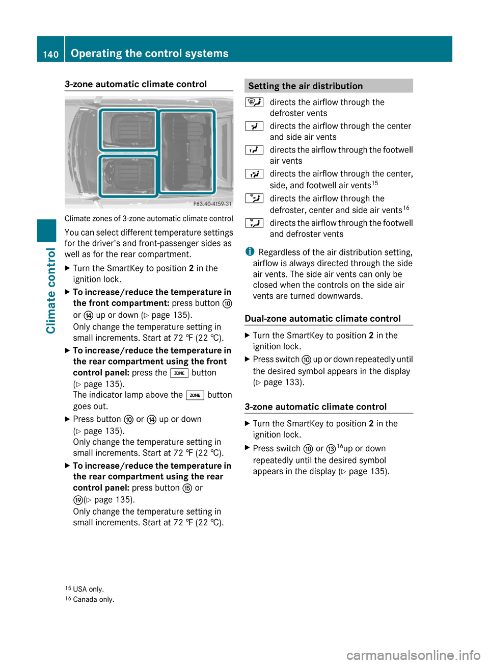
Climate zones of 3-zone automatic climate control
You can select different temperature settings
for the driver's and front-passenger sides as
well as for the rear compartment.
XTurn the SmartKey to position 2 in the
ignition lock.
XTo increase/reduce the temperature in
the front compartment: press button F
or J up or down (Y page 135).
Only change the temperature setting in
small increments. Start at 72 ‡ (22 †).
XTo increase/reduce the temperature in
the rear compartment using the front
control panel: press the á button
(Y page 135).
The indicator lamp above the á button
goes out.
XPress button F or J up or down
(Y page 135).
Only change the temperature setting in
small increments. Start at 72 ‡ (22 †).
XTo increase/reduce the temperature in
the rear compartment using the rear
control panel: press button K or
O(Y page 135).
Only change the temperature setting in
small increments. Start at 72 ‡ (22 †).
Setting the air distribution¯directs the airflow through the
defroster vents
Pdirects the airflow through the center
and side air vents
Odirects the airflow through the footwell
air vents
Sdirects the airflow through the center,
side, and footwell air vents15bdirects the airflow through the
defroster, center and side air vents16adirects the airflow through the footwell
and defroster vents
iRegardless of the air distribution setting,
airflow is always directed through the side
air vents. The side air vents can only be
closed when the controls on the side air
vents are turned downwards.
Dual-zone automatic climate control
XTurn the SmartKey to position 2 in the
ignition lock.
XPress switch F up or down repeatedly until
the desired symbol appears in the display
(Y page 133).
3-zone automatic climate control
XTurn the SmartKey to position 2 in the
ignition lock.
XPress switch F or I16up or down
repeatedly until the desired symbol
appears in the display (Y page 135).
15USA only.16Canada only.
140Operating the control systemsClimate control
BA 212 USA, CA Edition B 2011; 1; 5, en-USdimargiVersion: 3.0.3.62010-05-20T13:33:46+02:00 - Seite 140
Page 365 of 400

Determining the maximum load
The following steps have been developed as required of all manufacturers under Title 49, Code
of U.S. Federal Regulations, Part 575 pursuant to the "National Traffic and Motor Vehicle
Safety Act of 1966".XStep 1: Locate the statement "The combined weight of occupants and cargo should never
exceed XXX kg or XXX lbs." on your vehicle's Tire and Loading Information placard.XStep 2: Determine the combined weight of the driver and passengers that will be traveling
in your vehicle.XStep 3: Subtract the combined weight of the driver and passengers from XXX kilograms or
XXX lbs.XStep 4: The resulting figure equals the available amount of cargo and luggage load capacity.
For example, if the "XXX" amount equals 1400 lbs and there will be five 150 lbs passengers
in your vehicle, the amount of available cargo and luggage load capacity is 650 lbs (1400 -
750 (5 x 150) = 650 lbs).X Step 5: Determine the combined weight of luggage and cargo being loaded on the vehicle.
For reasons of safety, that weight must not exceed the available cargo and luggage cargo
capacity calculated in step 4.XStep 6 (if applicable): If you intend to tow a trailer behind your vehicle, the load on the
trailer is transferred to your vehicle. Consult this Operator's Manual to determine how this
reduces the available cargo and luggage load capacity of your vehicle ( Y page 365).
The following table shows examples of how to calculate total and cargo load capacities with
varying seating configurations and number and size of occupants. The following examples use
a cargo limit of 1500 lbs (680 kg). This is for illustration purposes only. Make sure you
always use the actual load limit for your vehicle stated on the vehicle's Tire and Loading
Information placard ( Y page 361).
Example 1Example 2Example 3Step 1Combined maximum
weight of occupants
and cargo (data from
the Tire and Loading
Information placard)1500 lbs
(680 kg)1500 lbs
(680 kg)1500 lbs
(680 kg)Example 1Example 2Example 3Step 2Number of people in
the vehicle (driver
and occupants)531Distribution of the
occupantsFront: 2
Rear: 3Front: 1
Rear: 2Front: 1Loading the vehicle363Tires and wheelsBA 212 USA, CA Edition B 2011; 1; 5, en-USdimargiVersion: 3.0.3.62010-05-20T13:33:46+02:00 - Seite 363Z
Page 366 of 400

Example 1Example 2Example 3Weight of the
occupantsOccupant 1:
150 lbs (68 kg)
Occupant 2:
180 lbs (82 kg)
Occupant 3:
160 lbs (73 kg)
Occupant 4:
140 lbs (63 kg)
Occupant 5:
120 lbs (54 kg)Occupant 1:
200 lbs (91 kg)
Occupant 2:
190 lbs (86 kg)
Occupant 3:
150 lbs (68 kg)Occupant 1:
150 lbs (68 kg)Gross weight of all
occupants750 lbs (340 kg)540 lbs (245 kg)150 lbs (68 kg)Example 1Example 2Example 3Step 3Permissible cargo
and trailer load/
noseweight
(maximum gross
vehicle weight rating
from the Tire and
Loading Information
placard minus the
gross weight of all
occupants)1500 lbs
(680 kg) -
750 lbs (340 kg)
= 750 lbs
(340 kg)1500 lbs
(680 kg) -
540 lbs (245 kg)
= 960 lbs
(435 kg)1500 lbs
(680 kg) -
150 lbs (68 kg) =
1350 lbs
(612 kg)
The greater the combined weight of the occupants, the lower the maximum luggage load.
Further information can be found under "Towing a trailer" ( Y page 365).
Vehicle identification plate
Even if you have calculated the total cargo
carefully, you should still make sure that the
gross vehicle weight rating and the gross axle
weight rating are not exceeded. Details can
be found on the vehicle identification plate on
the B-pillar on the driver's side (Y page 360).
Gross vehicle weight: the gross weight of
the vehicle, all passengers, cargo and trailer
load/noseweight (if applicable) must not
exceed the permissible gross vehicle weight.Gross axle weight rating: the maximum
permissible load that can be carried by one
axle (front or rear axle).
To ensure that your vehicle does not exceed
the maximum permissible values (gross
vehicle weight and maximum gross axle
weight rating), have your loaded vehicle
(including driver, occupants, cargo, and full
trailer load if applicable) weighed on a
suitable vehicle weighbridge.364Loading the vehicleTires and wheels
BA 212 USA, CA Edition B 2011; 1; 5, en-USdimargiVersion: 3.0.3.62010-05-20T13:33:46+02:00 - Seite 364