2011 MERCEDES-BENZ E350 4MATIC Start
[x] Cancel search: StartPage 319 of 400

! Do not use dry cloths, abrasive products,
solvents or cleaning agents containing
solvents to clean the inside of the windows.
Do not use hard objects to clean the insides
of the windows, e.g. an ice scraper or ring.
There is otherwise a risk of damaging the
windows.
! Clean the water drainage channels of the
windshield and the rear window at regular
intervals. Deposits such as leaves, petals
and pollen may under certain
circumstances prevent water from draining
away. This can lead to corrosion damage
and damage to electronic components.
Cleaning the wiper blades
GWarning
Switch off the windshield wipers and remove
the SmartKey from the ignition lock before
cleaning the windshield or the wiper blades.
On vehicles with KEYLESS-GO, press the
Start/Stop button repeatedly until all
indicator lamps in the instrument cluster have
gone off. The windshield wipers could
otherwise move and injure you.
! Do not pull the wiper blade. Otherwise,
the wiper blade could be damaged.
! Do not clean wiper blades too often and
do not rub them too hard. Otherwise, the
graphite coating could be damaged. This
could cause wiper noise.
XFold the wiper arms away from the
windshield.
XCarefully clean the wiper blades with a
damp cloth.
XFold the windshield wipers back again
before switching on the ignition.
! Hold the wiper arm securely when folding
back. The windshield could be damaged if
the wiper arm smacks against it suddenly.
Cleaning the headlampsXClean the plastic lamp lenses on the
headlamps using a wet sponge and a mild
cleaning agent, e.g. Mercedes-Benz car
shampoo or cleaning cloths.
! Only use cleaning agents or cleaning
cloths which are suitable for plastic
headlamp lenses. Unsuitable cleaning
agents or cleaning cloths could scratch or
damage the plastic headlamp lenses.
Cleaning the sensors
XClean sensors : of the driving systems
with water, car shampoo and a soft cloth.
! When cleaning the sensors with a power
washer, maintain a distance between the
vehicle and the nozzle of the power washer
of at least 11.8 in (30 cm). Information
about the correct distance is available from
the equipment manufacturer.
Care317Maintenance and careBA 212 USA, CA Edition B 2011; 1; 5, en-USdimargiVersion: 3.0.3.62010-05-20T13:33:46+02:00 - Seite 317Z
Page 323 of 400

Vehicle equipment ............................322
After an accident .............................. 323
Where will I find...? ...........................323
Flat tire .............................................. 326
Battery ............................................... 338
Jump-starting .................................... 341
Towing and tow-starting ..................343
Fuses .................................................. 345321Roadside AssistanceBA 212 USA, CA Edition B 2011; 1; 5, en-USdimargiVersion: 3.0.3.62010-05-20T13:33:46+02:00 - Seite 321
Page 325 of 400

After an accidentProblemPossible causes/consequences and M SolutionsFuel is leaking from the
vehicle.GRisk of explosion or fire
The fuel line or the fuel tank is faulty.
XImmediately turn the key to position 0(Y page 149)in the ignition
lock and remove it.XDo not restart the engine under any circumstances.XConsult a qualified specialist workshop.You are unable to
determine the extent of
the damage.XConsult a qualified specialist workshop.You cannot detect any
damage.XStart the engine as normal.The NECK-PRO head
restraints on the
driver's and front-
passenger seats have
been triggered.Your vehicle has been involved in a rear-end collision.XReset the triggered NECK-PRO head restraints ( Y page 53).Where will I find...?
First-aid kit
Sedan: the first-aid kit is in the right-hand
stowage compartment in the trunk.
XOpen the trunk lid.XSlide down the parcel net.XOpen the stowage compartment.XRelease strap :.XRemove first-aid kit ;.
Wagon: depending on the vehicle's
equipment, the first-aid kit is in the parcel net
or behind the side trim panel.
XOpen the tailgate.
In the parcel net
Where will I find...?323Roadside AssistanceBA 212 USA, CA Edition B 2011; 1; 5, en-USdimargiVersion: 3.0.3.62010-05-20T13:33:46+02:00 - Seite 323Z
Page 329 of 400

recommended that you additionally equip
your vehicle with the TIREFIT kit if you
mount tires that do not feature run-flat
properties, e.g. winter tires. You can obtain
a TIREFIT kit from an authorized Mercedes-
Benz Center, for example.
XVehicles with AIRMATIC: make sure that
"normal" level is selected (Y page 191).
XStop the vehicle as far away as possible
from traffic on solid, non-slippery and level
ground.
XSwitch on the hazard warning lamps.XFirmly depress the parking brake.XBring the front wheels into the straight-
ahead position.
XMove the selector lever/DIRECT SELECT
lever to P.
XSwitch off the engine.XVehicles without KEYLESS-GO: remove
the key from the ignition lock.
XVehicles with KEYLESS-GO: open the
driver's door.
The on-board electronics have status 0,
which is the same as the key having been
removed.
XVehicles with KEYLESS-GO: remove the
Start/Stop button from the ignition lock
(Y page 150).
XAll occupants must get out of the vehicle.
Make sure that they are not endangered as
they get out of the vehicle.
XMake sure that no one is near the danger
area whilst a wheel is being changed.
Anyone who is not directly assisting in the
wheel change should, for example, stand
behind the barrier.
XGet out of the vehicle. Pay attention to
traffic conditions when doing so.
XClose the driver's door.TIREFIT kit
Using the TIREFIT kit
You can use the TIREFIT kit to seal small
punctures, particularly those in the tire tread.
You can use TIREFIT at outside temperatures
down to -4 ‡ (-20 †).
GWarning
TIREFIT is a limited repair device. TIREFIT
cannot be used for cuts or punctures larger
than approximately 0.16 in (4 mm) and tire
damage caused by driving with extremely low
tire inflation pressure, or on a flat tire, or a
damaged wheel.
Do not drive the vehicle under such
circumstances.
Contact the nearest authorized Mercedes-
Benz Center for assistance or call roadside
assistance.
XDo not remove any foreign objects which
have penetrated the tire, e.g. screws or
nails.
XRemove the TIREFIT kit, the accompanying
"max. 80 km/h" sticker and the electric air
pump from the stowage well underneath
the trunk/trunk floor (Y page 324).
XAffix part : of the sticker within the
driver's field of vision.
XAffix part ; of the sticker near the valve
on the wheel with the defective tire.
Flat tire327Roadside AssistanceBA 212 USA, CA Edition B 2011; 1; 5, en-USdimargiVersion: 3.0.3.62010-05-20T13:33:46+02:00 - Seite 327Z
Page 335 of 400
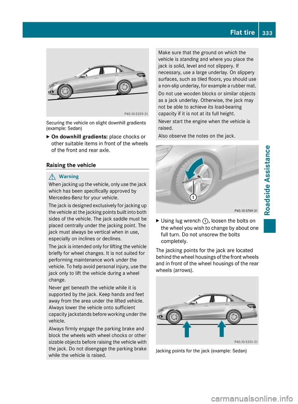
Securing the vehicle on slight downhill gradients(example: Sedan)
XOn downhill gradients: place chocks or
other suitable items in front of the wheels
of the front and rear axle.
Raising the vehicle
GWarning
When jacking up the vehicle, only use the jack
which has been specifically approved by
Mercedes-Benz for your vehicle.
The jack is designed exclusively for jacking up
the vehicle at the jacking points built into both
sides of the vehicle. The jack saddle must be
placed centrally under the jacking point. The
jack must always be vertical when in use,
especially on inclines or declines.
The jack is intended only for lifting the vehicle
briefly for wheel changes. It is not suited for
performing maintenance work under the
vehicle. To help avoid personal injury, use the
jack only to lift the vehicle during a wheel
change.
Never get beneath the vehicle while it is
supported by the jack. Keep hands and feet
away from the area under the lifted vehicle.
Always lower the vehicle onto sufficient
capacity jackstands before working under the
vehicle.
Always firmly engage the parking brake and
block the wheels with wheel chocks or other
sizable objects before raising the vehicle with
the jack. Do not disengage the parking brake
while the vehicle is raised.
Make sure that the ground on which the
vehicle is standing and where you place the
jack is solid, level and not slippery. If
necessary, use a large underlay. On slippery
surfaces, such as tiled floors, you should use
a non-slip underlay, for example a rubber mat.
Do not use wooden blocks or similar objects
as a jack underlay. Otherwise, the jack may
not be able to achieve its load-bearing
capacity if it is not at its full height.
Never start the engine when the vehicle is
raised.
Also observe the notes on the jack.
XUsing lug wrench :, loosen the bolts on
the wheel you wish to change by about one
full turn. Do not unscrew the bolts
completely.
The jacking points for the jack are located
behind the wheel housings of the front wheels
and in front of the wheel housings of the rear
wheels (arrows).
Jacking points for the jack (example: Sedan)
Flat tire333Roadside AssistanceBA 212 USA, CA Edition B 2011; 1; 5, en-USdimargiVersion: 3.0.3.62010-05-20T13:33:46+02:00 - Seite 333Z
Page 339 of 400

XVersion 2: stow connector = and the air
hose in the lower section of the pump
housing.XStow the electric air pump in the
designated place in the vehicle.
Lowering the vehicle
GWarning!
Vehicles with spare wheel with collapsible tire
only: Inflate collapsible tire only after the
wheel is properly attached.
Inflate the collapsible tire using the electric
air pump before lowering the vehicle.
XTurn the crank of the jack counter-
clockwise until the vehicle is once again
standing firmly on the ground.XPlace the jack to one side.XTighten the wheel bolts evenly in a
crosswise pattern in the sequence
indicated ( : to A). The tightening torque
must be 96 lb-ft (130 Nm) .GRisk of accident
Have the tightening torque checked
immediately after a wheel is changed. The
wheels could come loose if they are not
tightened to a torque of 96 lb-ft (130 Nm).
XTurn the jack back to its initial position and
store it together with the rest of the vehicle
tool kit in the trunk/cargo compartment.XAMG vehicles and vehicles with AMG
equipment: insert the cover into the outer
sill.
Vehicles with an emergency spare wheel:
XTransport the faulty wheel in the trunk/
cargo compartment.
or
XDepending on the size of the wheel, you
may also be able to secure the faulty wheel
in the spare wheel well. In this case, you
will have to remove the stowage well casing
from the spare wheel well and stow it
securely in the trunk/cargo compartment.
Further information on stowing the
collapsible spare wheel ( Y page 326).
i When you are driving with the collapsible
spare wheel mounted, the tire pressure
loss warning system or the tire pressure
monitor cannot function reliably. Only
restart the tire pressure loss warning
system/tire pressure monitor when the
defective wheel has been replaced with a
new wheel.
Vehicles with tire pressure monitor: all
mounted wheels must be equipped with
functioning sensors and the defective
wheel should no longer be in the vehicle.
MOExtended run-flat system
The MOExtended run-flat system allows you
to drive on even if there is a complete loss of
pressure in one or more tires.
The MOExtended run-flat system may only be
used in conjunction with the activated tire
pressure loss warning system or with the
activated tire pressure monitor.
The maximum permissible distance which
can be driven in run-flat mode depends on the
cargo in the vehicle. You can drive 50 miles
(80 km) if the vehicle is partially laden and
18 miles (30 km) if it is fully laden.
The maximum permissible distance which
can be driven in run-flat mode is counted from
Flat tire337Roadside AssistanceBA 212 USA, CA Edition B 2011; 1; 5, en-USdimargiVersion: 3.0.3.62010-05-20T13:33:46+02:00 - Seite 337Z
Page 340 of 400

the moment the tire pressure loss warning
appears in the multifunction display.
You must not exceed a maximum speed of
50 mph(80 km/h).GWarning!
The handling characteristics of your vehicle
deteriorate in run-flat mode, for example:
R when cornering
R when braking
R when accelerating rapidly
Adapt your driving style accordingly and avoid
sudden changes in direction and sudden
acceleration, as well as driving over obstacles
(i.e. curbs, potholes), and driving off-road.
This is particularly the case when the vehicle
is heavily laden.
The maximum permissible distance that can
be driven in run-flat mode depends to a large
extent on the loads placed on the vehicle. It
can be shorter due to high speeds, a heavy
cargo, sudden changes in direction, the road
surface condition, outside temperature, etc.,
or further if you drive carefully and
conservatively.
Do not continue to drive in run-flat mode if:
R you hear banging noises.
R the vehicle starts to shake.
R you see smoke and smell rubber.
R ESP ®
is intervening constantly.
R there are tears in the sidewalls of the tire.
After driving in run-flat mode, you must have
the wheel(s) checked for damage at a
qualified specialist workshop which has the
necessary specialist knowledge and tools to
carry out the work required. The faulty tire
must be replaced in every case.
Mercedes-Benz recommends that you use an
authorized Mercedes-Benz Center for this
purpose. In particular, work relevant to safety
or on safety-related systems must be carried
out at a qualified specialist workshop.
i When replacing one or all tires, make sure
that you only use tires marked
MOExtended and of the specified size for
the vehicle.
i Vehicles featuring the MOExtended run-
flat system are not equipped with TIREFIT
kit at the factory. It is therefore
recommended that you additionally equip
your vehicle with the TIREFIT kit if you
mount tires that do not feature run-flat
properties, e.g. winter tires. You can obtain
a TIREFIT kit from an authorized Mercedes-
Benz Center, for example.
Battery
Important safety notes
In order for the battery to achieve the
maximum possible service life, it must always
be sufficiently charged.
! Have the battery checked regularly at a
qualified specialist workshop, e.g. an
authorized Mercedes-Benz Center.
Observe the service intervals in the Service
Booklet or for further information consult a
qualified specialist workshop, e.g. an
authorized Mercedes-Benz Center.
Have the battery charge checked more
frequently if you use the vehicle mainly for
short trips or if you leave it standing idle for
a lengthy period.
To prevent damage from corrosion, only
replace the battery with one that has a central
ventilation cover.
Only replace a battery with a battery that has
been recommended by Mercedes-Benz.
Consult an authorized Mercedes-Benz Center
if you wish to leave your vehicle parked up for
a long period of time.
GWarning
Comply with safety precautions and take
protective measures when handling batteries.
338BatteryRoadside Assistance
BA 212 USA, CA Edition B 2011; 1; 5, en-USdimargiVersion: 3.0.3.62010-05-20T13:33:46+02:00 - Seite 338
Page 342 of 400

The battery, breather hose and cover of the
positive terminal clamp must be installed
securely during operation.
i Remove the key if you park the vehicle
and do not require any electrical
consumers. The vehicle will then use very
little energy, thus conserving battery
power.
Mercedes-Benz recommends that you do not
carry out work on batteries yourself, e.g.
removing, charging or replacing. Always have
this work performed at a qualified specialist
workshop, e.g. an authorized Mercedes-Benz
Center.
Charging the battery
GWarning
Never charge a battery while still installed in
the vehicle unless the accessory battery
charge unit approved by Mercedes-Benz is
being used. Gases may escape during
charging and cause explosions that may
result in paint damage, corrosion or personal
injury.
An accessory battery charge unit specially
adapted for Mercedes-Benz vehicles and
tested and approved by Mercedes-Benz is
available. It permits the charging of the
battery in its installed position. Contact an
authorized Mercedes-Benz Center for
information and availability.
Charge the battery in accordance with the
separate instructions for the accessory
battery charger.
GWarning!
There is a risk of acid burns during the
charging process due to the gases which
escape from the battery. Do not lean over the
battery during the charging process.
GWarning!
Battery acid is caustic. Avoid contact with the
skin, eyes or clothing.
! Only charge the installed battery with a
battery charger which has been tested and
approved by Mercedes-Benz. These battery
chargers allow the battery to be charged
while still installed.
! Only use battery chargers with a
maximum charging voltage of 14.8 V.
! Only charge the battery using the jump-
starting connection point.
The jump-starting connection point is in the
engine compartment ( Y page 341).XOpen the hood ( Y page 308).XConnect the battery charger to the positive
terminal and earth point in the same order
as when connecting the donor battery in
the jump-starting procedure
( Y page 341).340BatteryRoadside Assistance
BA 212 USA, CA Edition B 2011; 1; 5, en-USdimargiVersion: 3.0.3.62010-05-20T13:33:46+02:00 - Seite 340