2011 MERCEDES-BENZ E-CLASS ESTATE change time
[x] Cancel search: change timePage 248 of 409
X
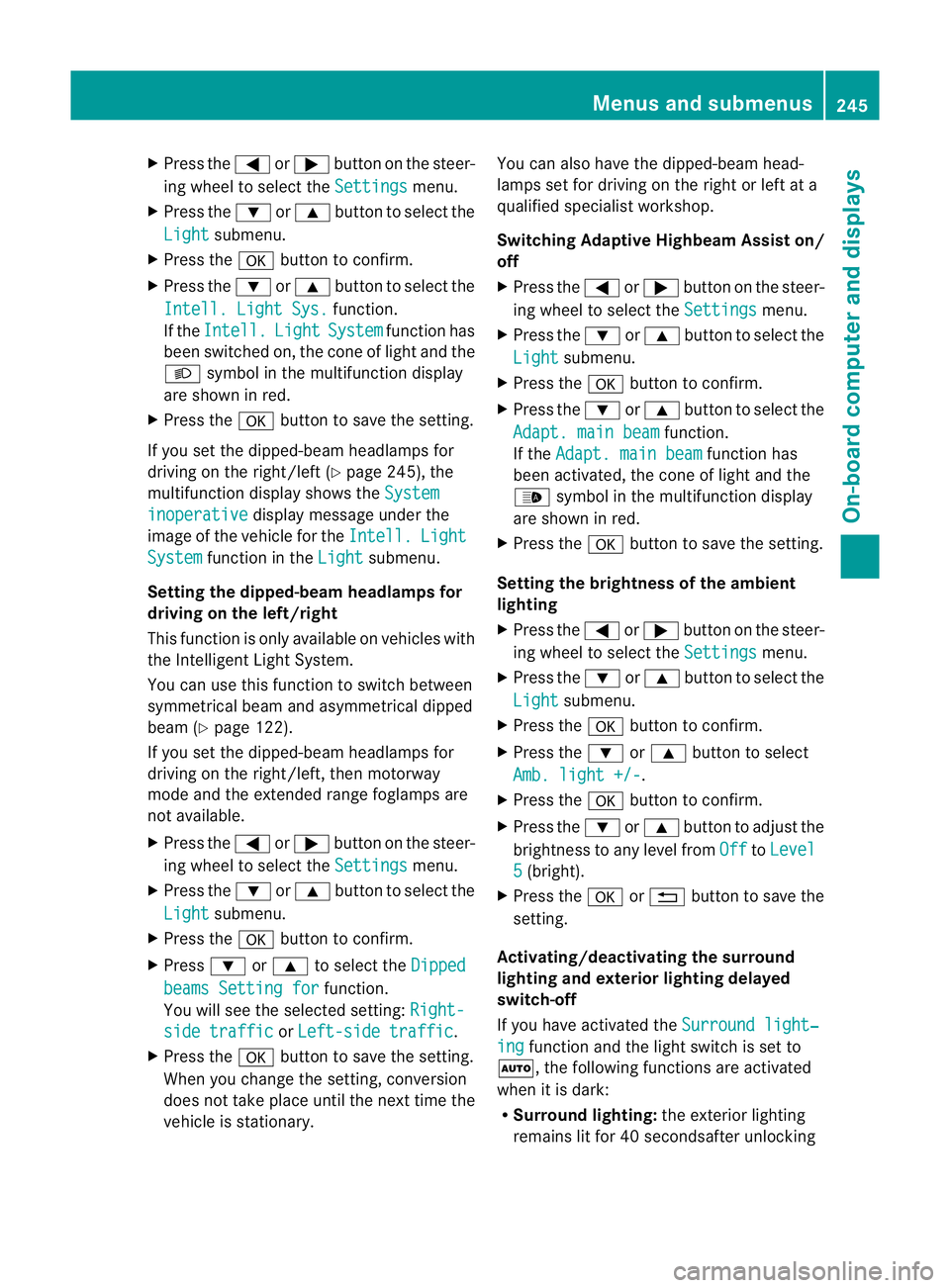
Press the =or; button on the steer-
ing wheel to select the Settings menu.
X Press the :or9 button to select the
Light submenu.
X Press the abutton to confirm.
X Press the :or9 button to select the
Intell. Light Sys. function.
If the Intell. Light System function has
been switched on, the cone of light and the
L symbol in the multifunction display
are shown in red.
X Press the abutton to save the setting.
If you set the dipped-beam headlamps for
driving on the right/left (Y page 245), the
multifunction display shows the Systeminoperative display message under the
image of the vehicle for the Intell. Light
System function in the
Light submenu.
Setting the dipped-beam headlamps for
driving on the left/right
This function is only available on vehicles with
the Intelligent Light System.
You can use this function to switch between
symmetrical beam and asymmetrical dipped
beam (Y page 122).
If you set the dipped-beam headlamps for
driving on the right/left, then motorway
mode and the extended range foglamps are
not available.
X Press the =or; button on the steer-
ing wheel to select the Settings menu.
X Press the :or9 button to select the
Light submenu.
X Press the abutton to confirm.
X Press :or9 to select the Dipped beams Setting for function.
You will see the selected setting: Right-side traffic or
Left-side traffic .
X Press the abutton to save the setting.
When you change the setting, conversion
does not take place until the next time the
vehicle is stationary. You can also have the dipped-beam head-
lamps set for driving on the right or left at a
qualified specialist workshop.
Switching Adaptive Highbeam Assist on/
off
X
Press the =or; button on the steer-
ing wheel to select the Settings menu.
X Press the :or9 button to select the
Light submenu.
X Press the abutton to confirm.
X Press the :or9 button to select the
Adapt. main beam function.
If the Adapt. main beam function has
been activated, the cone of light and the
_ symbol in the multifunction display
are shown in red.
X Press the abutton to save the setting.
Setting the brightness of the ambient
lighting
X Press the =or; button on the steer-
ing wheel to select the Settings menu.
X Press the :or9 button to select the
Light submenu.
X Press the abutton to confirm.
X Press the :or9 button to select
Amb. light +/- .
X Press the abutton to confirm.
X Press the :or9 button to adjust the
brightness to any level from Off to
Level 5 (bright).
X Press the aor% button to save the
setting.
Activating/deactivating the surround
lighting and exterior lighting delayed
switch-off
If you have activated the Surround light‐ ing function and the light switch is set to
Ã, the following functions are activated
when it is dark:
R Surround lighting: the exterior lighting
remains lit for 40 secondsafter unlocking Menus and submenus
245On-board computer and displays Z
Page 250 of 409
X
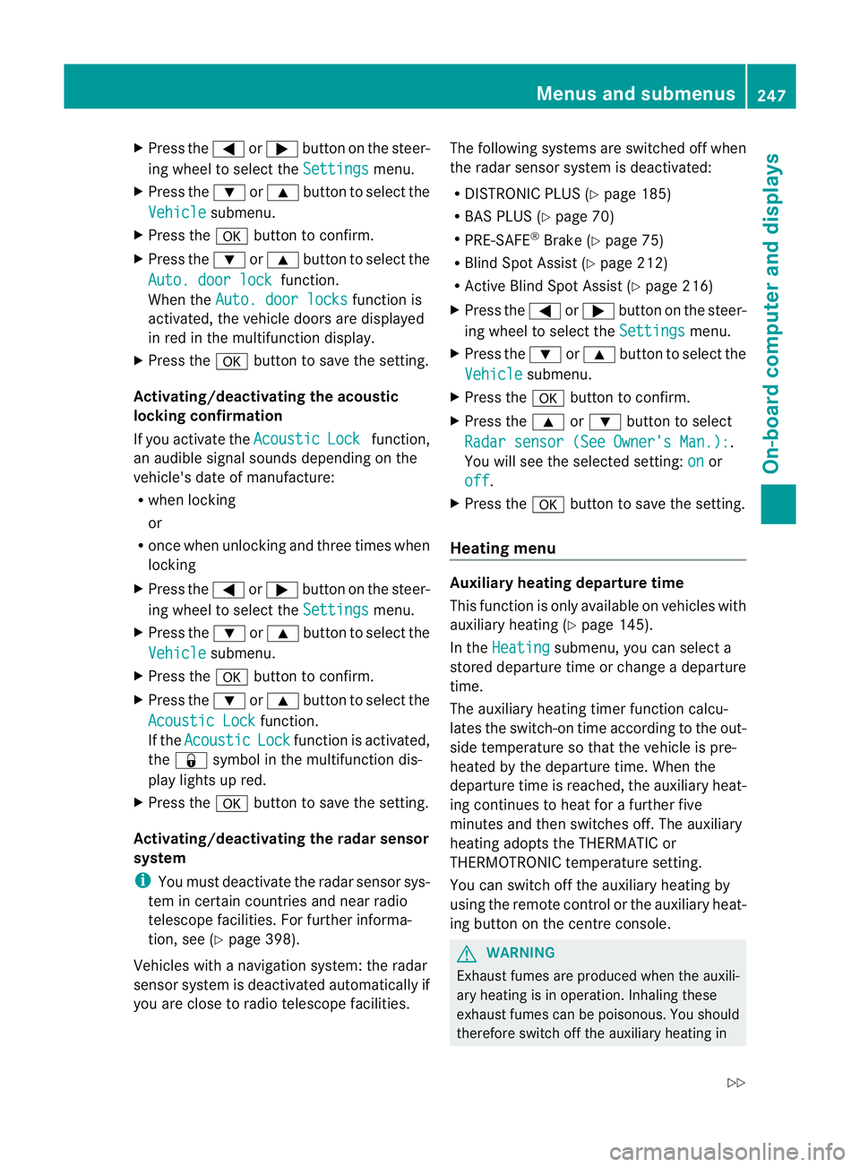
Press the =or; button on the steer-
ing wheel to select the Settings menu.
X Press the :or9 button to select the
Vehicle submenu.
X Press the abutton to confirm.
X Press the :or9 button to select the
Auto. door lock function.
When the Auto. door locks function is
activated, the vehicle doors are displayed
in red in the multifunction display.
X Press the abutton to save the setting.
Activating/deactivating the acoustic
locking confirmation
If you activate the Acoustic Lock function,
an audible signal sounds depending on the
vehicle's date of manufacture:
R when locking
or
R once when unlocking and three times when
locking
X Press the =or; button on the steer-
ing wheel to select the Settings menu.
X Press the :or9 button to select the
Vehicle submenu.
X Press the abutton to confirm.
X Press the :or9 button to select the
Acoustic Lock function.
If the Acoustic Lock function is activated,
the & symbol in the multifunction dis-
play lights up red.
X Press the abutton to save the setting.
Activating/deactivating the radar sensor
system
i You must deactivate the radar sensor sys-
tem in certain countries and near radio
telescope facilities. For further informa-
tion, see (Y page 398).
Vehicles with a navigation system: the radar
sensor system is deactivated automatically if
you are close to radio telescope facilities. The following systems are switched off when
the radar sensor system is deactivated:
R
DISTRONIC PLUS (Y page 185)
R BAS PLUS (Y page 70)
R PRE-SAFE ®
Brake (Y page 75)
R Blind Spot Assist (Y page 212)
R Active Blind Spot Assist (Y page 216)
X Press the =or; button on the steer-
ing wheel to select the Settings menu.
X Press the :or9 button to select the
Vehicle submenu.
X Press the abutton to confirm.
X Press the 9or: button to select
Radar sensor (See Owner's Man.): .
You will see the selected setting: on or
off .
X Press the abutton to save the setting.
Heating menu Auxiliary heating departure time
This function is only available on vehicles with
auxiliary heating (Y
page 145).
In the Heating submenu, you can select a
stored departure time or change a departure
time.
The auxiliary heating timer function calcu-
lates the switch-on time according to the out-
side temperature so that the vehicle is pre-
heated by the departure time. When the
departure time is reached, the auxiliary heat-
ing continues to heat for a further five
minutes and then switches off. The auxiliary
heating adopts the THERMATIC or
THERMOTRONIC temperature setting.
You can switch off the auxiliary heating by
using the remote control or the auxiliary heat-
ing button on the centre console. G
WARNING
Exhaust fumes are produced when the auxili-
ary heating is in operation. Inhaling these
exhaust fumes can be poisonous. You should
therefore switch off the auxiliary heating in Menus and submenus
247On-board computer and displays
Z
Page 251 of 409
confined spaces withou
tanextraction sys-
tem, e.g. a garage. G
WARNING
Whe noperating the auxiliary heating parts of
the vehicle can get very hot. Make sure that
the exhaust system does not under any cir-
cumstances come into contact with easily
ignitable material such as dry grass or fuels.
The material could otherwise ignite and set
the vehicle alight. Choose your parking spot
accordingly.
Operating the auxiliary heating is thus pro-
hibited at filling stations or when your vehicle
is being refuelled. You must therefore switch
off the auxiliary heating at filling stations.
! Operating the auxiliary heating/ventila-
tion draws on the vehicle battery. After you
have heated or ventilated the vehicle a
maximum of two times, drive for a longer
distance.
i Switch the auxiliary heating on regularly
once a month for about ten minutes.
Selecting the departure time or deactivat-
ing a selected departure time
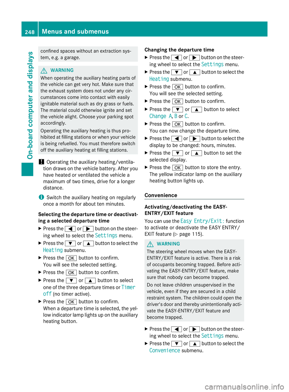
X Press the =or; buttononthe steer-
ing wheel to select the Settings menu.
X Press the :or9 button to select the
Heating submenu.
X Press the abutton to confirm.
You will see the selected setting.
X Press the abutton to confirm.
X Press the :or9 button to select
one of the three departure times or Timeroff (no timer active).
X Press the abutton to confirm.
When a departure time is selected, the yel-
low indicator lamp lights up on the auxiliary
heating button. Changing the departure time
X
Press the =or; button on the steer-
ing wheel to select the Settings menu.
X Press the :or9 button to select the
Heating submenu.
X Press the abutton to confirm.
You will see the selected setting.
X Press the abutton to confirm.
X Press the :or9 button to select
Change A ,
B or
C .
X Press the abutton to confirm.
You can now change the departure time.
X Press the =or; button to select the
display to be changed: hours, minutes.
X Press the :or9 button to set the
selected display.
X Press the abutton to store the entry.
The yellow indicator lamp on the auxiliary
heating button lights up.
Convenience Activating/deactivating the EASY-
ENTRY/EXIT feature
You can use the
Easy Entry/Exit: function
to activate or deactivate the EASY ENTRY/
EXIT feature (Y page 115). G
WARNING
The steering wheel moves when the EASY-
ENTRY/EXIT feature is active. There is a risk
of occupants becoming trapped. Before acti-
vating the EASY-ENTRY/EXIT feature, make
sure that nobody can become trapped.
Do not leave children unsupervised in the
vehicle, even if they are secured in a child
restraint system. The children could open the
driver's door and thereby unintentionally acti-
vate the EASY-ENTRY/EXIT feature and
become trapped.
X Press the =or; button on the steer-
ing wheel to select the Settings menu.
X Press the :or9 button to select the
Convenience submenu.248
Menus and submenusOn-board computer and displays
Page 264 of 409
Display messages Possible causes/consequences and
M Solutions
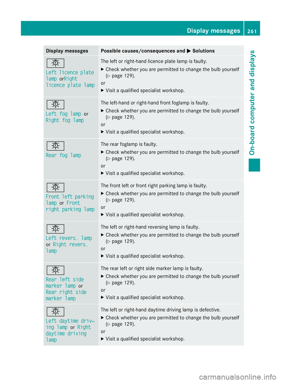
b
Left
licence plate
lamp orRight
licence plate lamp The lef
torright-hand licence plate lamp is faulty.
X Check whether you are permitted to change the bulb yourself
(Y page 129).
or
X Visit a qualified specialist workshop. b
Left fog lamp
or
Right fog lamp The left-hand or right-hand front foglamp is faulty.
X Check whether you are permitted to change the bulb yourself
(Y page 129).
or
X Visit a qualified specialist workshop. b
Rear fog lamp The rear foglamp is faulty.
X
Check whether you are permitted to change the bulb yourself
(Y page 129).
or
X Visit a qualified specialist workshop. b
Front
left parking
lamp or
Front right parking lamp The front left or front right parking lamp is faulty.
X
Check whether you are permitted to change the bulb yourself
(Y page 129).
or
X Visit a qualified specialist workshop. b
Left revers. lamp
or
Right revers. lamp The left or right-hand reversing lamp is faulty.
X
Check whether you are permitted to change the bulb yourself
(Y page 129).
or
X Visit a qualified specialist workshop. b
Rear left side
marker lamp or
Rear right side marker lamp The rear left or right side marker lamp is faulty.
X
Check whether you are permitted to change the bulb yourself
(Y page 129).
or
X Visit a qualified specialist workshop. b
Left daytime driv‐
ing lamp or
Right daytime driving
lamp The left or right-hand daytime driving lamp is defective.
X
Check whether you are permitted to change the bulb yourself
(Y page 129).
or
X Visit a qualified specialist workshop. Display messages
261On-board computer and displays Z
Page 293 of 409
Useful information
i This Owner's Manual describes all models
and all standard and optional equipment
available to your vehicle at the time of pub-
lication of the Owner's Manual. Country-
specific deviations are possible. Please
note that your vehicle may not be equipped
with all features described. This also
applies to safety-relevan tsystems and
functions.
i Please read the information on qualified
specialist workshops (Y page 25).Loading guidelines
G
WARNING
Secure and position the load as described in
the loading guidelines.
Otherwise, vehicle occupants could
be injured by the load being throw naround in
the event of sharp braking, a sudden change
in direction or an accident.
You will find further informatio ninthe "Secur-
ing a load" section.
Even if you follow all the loading guidelines,
the load will increase the risk of injury in the
event of an accident. G
WARNING
Keep the boot lid/tailgate closed while the
vehicle is in operation. Otherwise, exhaust
fumes could enter the vehicle interior and poi-
son you.
The handling characteristics of a laden vehi-
cle are dependent on the distribution of the
load within the vehicle. For this reason, you
should observe the following notes when
transporting a load:
R when transporting a load, never exceed the
maximum permissible gross vehicle weight or the permissible axle loads for the vehicle
(including occupants).
R position heavy loads as far forwards as pos-
sible and as low down in the boot/luggage
compartmenta s possible.
R the load must not protrude above the upper
edge of the seat backrests.
R always place the load against the rear or
front seat backrests. Make sure that the
seat backrests are securely locked into
place.
R always place the load behind unoccupied
seats if possible.
R secure the load with sufficiently strong and
wear-resistant lashing material. Pad sharp
edges for protection.
i Lashing material is available at any quali-
fied specialist workshop. Stowage areas
Stowage compartments
Important safety notes G
WARNING
The stowage compartments must be closed
when items are stored in them. Luggage nets
are not designed to secure heavy items of
luggage.
You or other vehicle occupants could be
injured by objects being thrown around if you:
R brake sharply
R change direction suddenly
R are involved in an accident
Sharp-edged and fragile objects must not be
placed in the luggage net.
Do not place hard objects in the map pockets.
Objects must not protrude from the map
pockets. 290
Stowage areasStowing and features
Page 335 of 409
parts may break away and be thrown around
the interior when an airbag is deployed, which
may result in severe injuries.
! Do not affix the following to plastic surfa-
ces:
R stickers
R films
R scented oil bottles or similar items
You could otherwise damage the plastic.
! Do not allow cosmetics, insec trepellent
or sunscreen to come in contact with the
plastic trim .This maintains the high-quality
look of the surfaces.
X Wipe the plastic trim with a damp, lint-free
cloth, e.g. a microfibre cloth.
X Heavy soiling: use car care and cleaning
products recommended and approved by
Mercedes-Benz.
The surface may change colour tempora-
rily. Wait until the surface is dry again.
Cleaning the steering wheel and gear or
selector lever X
Thoroughly wipe with a damp cloth or use
leather care agents that have been recom-
mended and approved by Mercedes-Benz.
Cleaning wooden trim and trim ele-
ments X
Wipe the wooden trim and trim pieces with
a damp, lint-free cloth, e.g. a microfibre
cloth.
X Heavy soiling: use car care and cleaning
products recommended and approved by
Mercedes-Benz.
! Do not use solvent-based cleaning agents
such as tar remover, wheel cleaners, pol-
ishes or waxes. There is otherwise a risk of
damaging the surface. Cleaning the seat covers !
Do not use microfibre cloths to clean gen-
uine leather, artificial leather or
Alcantara® covers. If used often, these can
damage the cover.
! Observe the following when cleaning:
R clean genuine leather covers carefully
with a damp cloth and then wipe the cov-
ers down with a dry cloth. Make sure that
the leather does not become soaked. It
may otherwise become rough and
cracked. Only use leather care agents
that have been tested and approved by
Mercedes-Benz. You can obtain these
from a qualified specialist workshop.
R clean artificial leather covers with a cloth
moistened with a solution containing 1%
detergent (e.g. washing-up liquid).
R clean cloth covers with a microfibre cloth
moistened with a solution containing 1%
detergent (e.g. washing-up liquid). Rub
carefully and always wipe entire seat sec-
tions to avoid leaving visible lines. Leave
the seat to dry afterwards. Cleaning
results depend on the type of dirt and
how long it has been there.
R clean Alcantara® covers with a damp
cloth. Make sure that you wipe entire
seat sections to avoid leaving visible
lines.
i Note that regular care is essential to
make sure that the appearance and com-
fort of the covers are retained over time.
Cleaning the seat belts X
Use clean, lukewarm water and soap solu-
tion.
! Do not clean the seat belts using chemical
cleaning agents. Do not dry the seat belts
at temperatures above 80 † or in direct
sunlight. 332
CareMaintenance and care
Page 345 of 409
If you come into contact with the tyre sealant,
observe the following:
R
Rinse off the tyre sealant from your skin
immediately with water.
R If the tyre sealant comes into contact with
youre yes, immediately rinse them thor-
oughly with clean water.
R If tyre sealant is swallowed, immediately
rinse your mouth out thoroughly and drink
plenty of water. Do not induce vomiting,
and see kmedical attention immediately.
R Immediately change out of clothing which
has come into contact with tyre sealant.
R If an allergic reaction occurs, seek medical
attention immediately.
i If tyre sealant leaks out, allow it to dry. It
can then be removed like a layer of film.
If you get tyre sealant on your clothing,
have it cleaned as soon as possible with
perchloroethylene. X
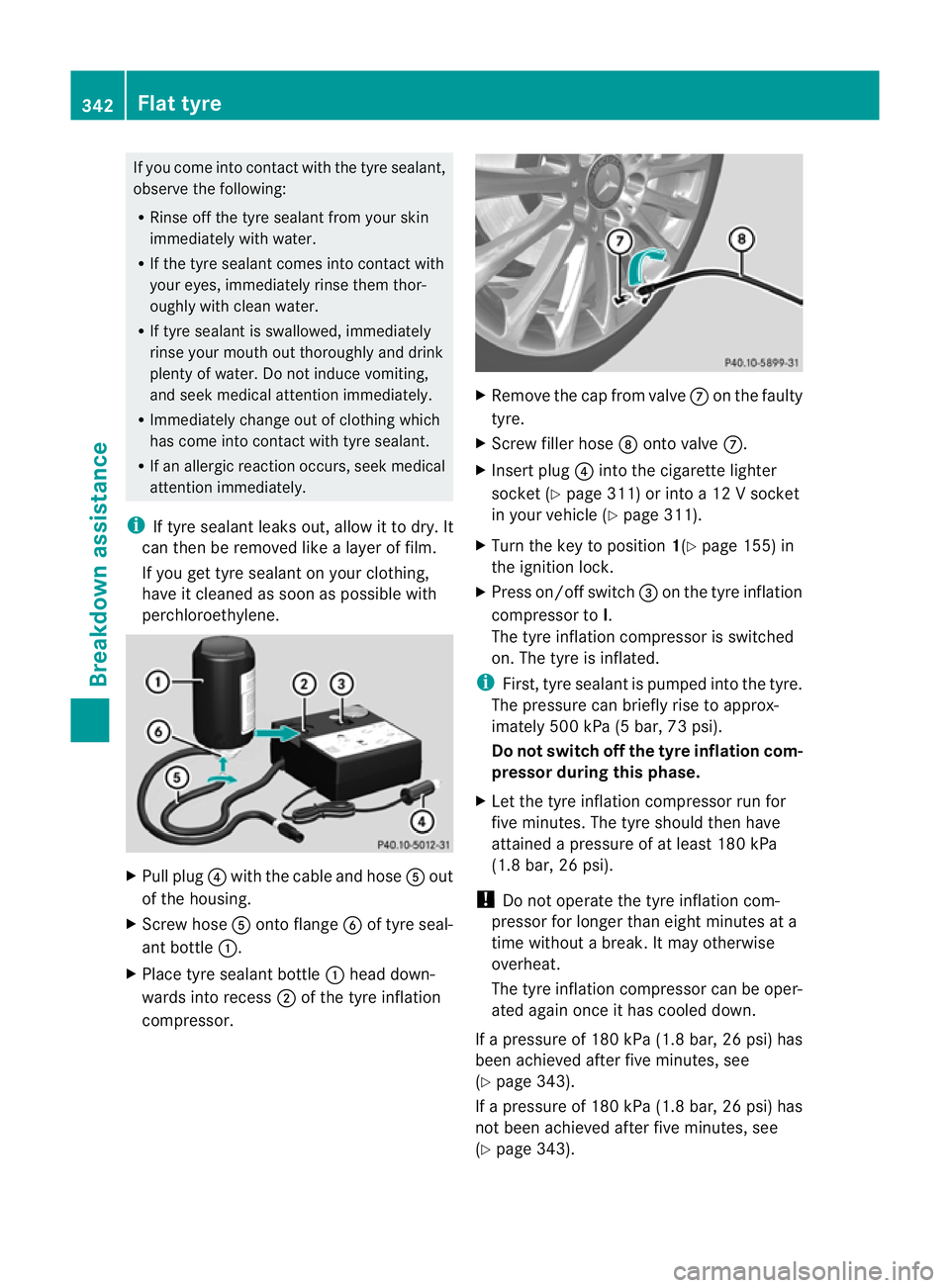
Pull plug ?with the cable and hose Aout
of the housing.
X Screw hose Aonto flange Bof tyre seal-
ant bottle :.
X Place tyre sealant bottle :head down-
wards into recess ;of the tyre inflation
compressor. X
Remove the cap from valve Con the faulty
tyre.
X Screw filler hose Donto valve C.
X Inser tplug ?into the cigarette lighter
socket (Y page 311) or into a 12 V socket
in your vehicle (Y page 311).
X Turn the key to position 1(Ypage 155) in
the ignition lock.
X Press on/off switch =on the tyre inflation
compressor to I.
The tyre inflation compressor is switched
on. The tyre is inflated.
i First, tyre sealant is pumped into the tyre.
The pressure can briefly rise to approx-
imately 500 kPa (5 bar, 73 psi).
Do not switch off the tyre inflation com-
pressor during this phase.
X Let the tyre inflation compressor run for
five minutes .The tyre should then have
attained a pressure of at least 180 kPa
(1.8 bar, 26 psi).
! Do not operate the tyre inflation com-
pressor for longer than eight minutes at a
time without a break. It may otherwise
overheat.
The tyre inflation compressor can be oper-
ated again once it has cooled down.
If a pressure of 180 kPa (1.8 ba r,26 psi) has
bee nachieved afte rfive minutes, see
(Y page 343).
If a pressure of 180 kPa (1.8 ba r,26 psi) has
not bee nachieved afte rfive minutes, see
(Y page 343). 342
Flat tyreBreakdown assistance
Page 348 of 409
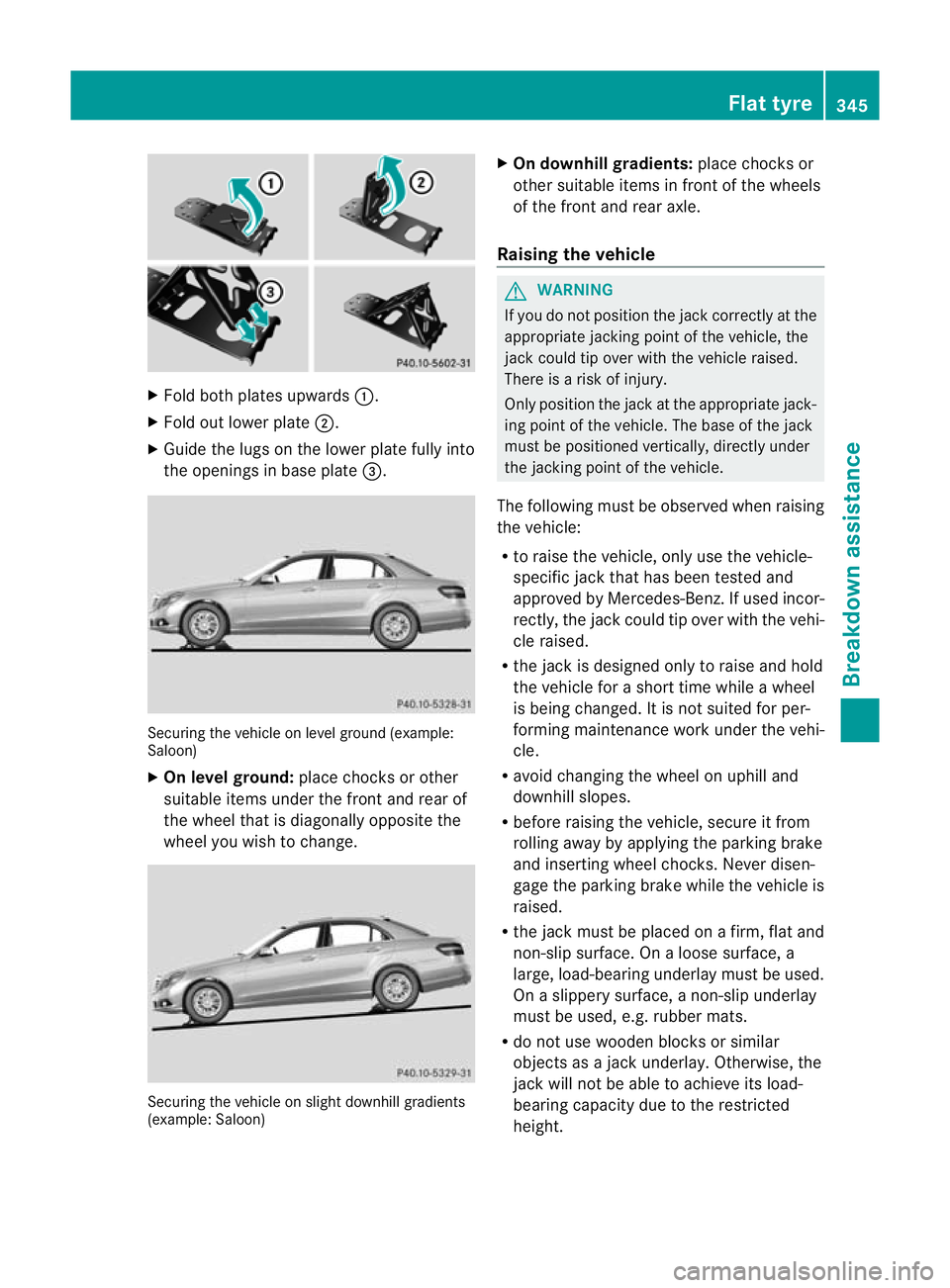
X
Fold both plates upwards :.
X Fold ou tlower plate ;.
X Guide the lugs on the lower plate fully into
the openings in base plate =.Securing the vehicle on level ground (example:
Saloon)
X
On level ground: place chocks or other
suitable items under the front and rear of
the wheel that is diagonally opposite the
wheel you wish to change. Securing the vehicle on slight downhill gradients
(example: Saloon) X
On downhill gradients: place chocks or
other suitable items in front of the wheels
of the front and rear axle.
Raising the vehicle G
WARNING
If you do not position the jack correctly at the
appropriate jacking point of the vehicle, the
jack could tip over with the vehicle raised.
There is a risk of injury.
Only position the jack at the appropriate jack-
ing point of the vehicle. The base of the jack
must be positioned vertically, directly under
the jacking point of the vehicle.
The following must be observed when raising
the vehicle:
R to raise the vehicle, only use the vehicle-
specific jack that has been tested and
approved by Mercedes-Benz. If used incor-
rectly, the jack could tip over with the vehi-
cle raised.
R the jack is designed only to raise and hold
the vehicle for a short time while a wheel
is being changed. It is not suited for per-
forming maintenance work under the vehi-
cle.
R avoid changing the wheel on uphill and
downhill slopes.
R before raising the vehicle, secure it from
rolling away by applying the parking brake
and inserting wheel chocks. Never disen-
gage the parking brake while the vehicle is
raised.
R the jack must be placed on a firm, flat and
non-slip surface. On a loose surface, a
large, load-bearing underlay must be used.
On a slippery surface, a non-slip underlay
must be used, e.g. rubber mats.
R do not use wooden blocks or similar
objects as a jack underlay. Otherwise, the
jack will not be able to achieve its load-
bearing capacity due to the restricted
height. Flat tyre
345Breakdown assistance Z